


Utilization of High Efficient MPPT Techniques of Photovoltaic (Pv) Systems Under Partially Shaded Conditions
Abdulkareem Alotaibi and Abdullah Al-Shaalan M*
Plastic Liquid Crystal Technology, Via Lambro 80, 20846 Macherio (MB), Italy
Submission: May 01, 2024; Published: May 24, 2024
*Corresponding author: Abdullah M Al Shaalan, Electrical Engineering department, King saud Univresity Riyadh, Saudi Arabia
How to cite this article: Abdulkareem Alotaibi and Abdullah Al-Shaalan M*. Utilization of High Efficient MPPT Techniques of Photovoltaic (Pv) Systems Under Partially Shaded Conditions. Trends Tech Sci Res. 2024; 7(1): 555705. DOI: 10.19080/TTSR.2024.07.555705
Abstract
This paper provides a comparison between maximum power point tracking (MPPT) hybrid techniques, applied to photovoltaic system (PV),This paper presents a comparative analysis of five MPPT methods these techniques are particle swarm optimization (PSO), Perturb & Observe (P&O), Fuzzy Logic Control (FLC), Incremental conductance (IC) and Hybrid (Fuzzy Logic Control (FLC) and Perturb & Observe (P&O)), under partially shaded conditions. MATLAB SIMULINK has been used for the analysis and the relevant results are discussed in detail. Using of different techniques of MPPT will show the difference of output voltage in partial shaded conditions and after the simulation and analyzing of the results with the same inputs used including but not limit to (same PV module, brand, irradiation, temperature, changing time, period of simulation... etc.). The comparison of all algorithms is focused on determining which one of the algorithms provide more efficiency to the PV system, i.e., which one of the algorithms, more effectively track the Maximum Power Point during slow and highly changing Irradiance to conclude in that way and which one of the algorithms could offer the best efficiency during real scenarios.
Keywords: Photovoltaic; Maximum power point tracker; Perturb and Observe; Incremental Conductance; Particle Swarm Optimization; Fuzzy Logic Control (FLC)
Abbreviations: MPPPT: Maximum Power Point Tracking; PV: Photovoltaic System; PSO: Particle Swarm Optimization; P&O: Perturb & Observe; FLC: Fuzzy Logic Control; IC: Incremental Conductance; SP: Series - Parallel; CSA: Cuckoo Search Algorithm; EPP: Estimate-Perturb-Perturb; HC: Hill Climbing; INC: Incremental Conductance
Introduction
Increasing environmental concerns, dwindling fuel reserves, and rising energy needs has directed our attention towards the glimmer of aspiration for a future totally based on renewable and nonpolluting energy supply technology. Power generation through Photovoltaic (PV) is increasingly becoming popular in comparison to other renewable resources owing to its advantages like easy availability, low cost, negligible environmental pollution, and lesser maintenance tariff. Despite having so many advantages, performance of PV generation is greatly opposed by its sensitivity towards two environmental factors namely temperature and irradiance. In earlier times, single PV modules were in high demand but due to the increasing demand of power in modern world, these are replaced by group of PV modules Connected in series - parallel (SP) combination. The relationship between voltage and current of a PV panel follows a non-linear path and hence it becomes imperative for us to find the optimum operating point so that we can extract the maximum output from the panel. However, the conversion efficiency of PV panel is quite low and is greatly affected by weather conditions like change in irradiation and temperature levels.
The environmental conditions are not always constant as we don’t always have constant value of irradiance and temperature as a result we obtain multiple peaks on P-V characteristics under partial shaded conditions. The correlation between the loads of most power systems and the generated power from the PV makes it an effective option used to feed increased loads during the daytime. Numerous developments have been introduced into PV systems to increase their efficiency and reduce the cost of generated energy, by using new and modified mate-rials or improving the power modifier performance. One of the most important devices used to increase the efficiency of PV systems is the maximum power point tracker (MPPT). Within this context, this paper presents the performance analysis among three MPPT techniques under partial shading conditions. The specific scope of my research paper comprehends the following issues:
a) Brief discussion on PV System.
b) Description of five MPPT techniques namely Perturb and Observe, Incremental Conductance, Particle Swarm Optimization, Fuzzy Logic Control (FLC) and Hybrid (Fuzzy Logic Control (FLC) and Perturb & Observe (P&O)).
c) Performance analysis under partial shading conditions. The Modeling and Simulation has been done under MATLAB 2022a environment and the algorithms are tested under two patterns of shading.
Advantages of Photovoltaic Systems
The advantages of photovoltaic [16] systems are:
i. PV systems are supposed static electricity generators as they generate electricity instantly from sunlight. They come prepackaged, waiting to be mounted and wired. Modules contain no moving parts, eliminating service and maintenance requirements.
ii. PV systems come in a variety of sizes and outputs suitable for various applications.
iii. They are lightweight, letting for easy and reliable transportation.
iv. PV systems can be quickly expanded by adding more extra modules either in series to expand the system’s voltage or in parallel to increase the Current.
v. PV systems are created to endure the roughest conditions. Modules are designed to endure intense temperatures, at any altitude, in high winds, and with any degree of moisture or salt in the environment. Systems can be planned with storage capabilities to provide regular, high-quality power still when the sun isn’t shining.
vi. PV systems produce no noise or carbon emissions, i.e. no pollution.
Disadvantages of Photovoltaic Systems
The disadvantages of photovoltaic systems are:
a) Very high building cost compared to other renewable resources.
b) Maximum power point problem.
c) Needs regular cleaning of its outer surfaces from dust.
d) Significantly low inefficiency.
Basic Types of PV Cells
Photovoltaic cells are produced in different forms; each has its uses and advantages compared to others. The most popular PV types are [16].
Mono-crystalline (single crystalline) cells: Monocrystalline cells are cut from a single crystal of silicon, they are a slice of crystal which makes them very sleek in texture. Monocrystalline cells are the most effective, but also the costliest to produce.
Poly-crystalline (multi-crystalline) cells: Polycrystalline cells are formed from a slice cut from a block of silicon, unlike Mono- these cells consist of a huge number of crystals. Photovoltaic solar panels made from these kinds of cells are somewhat less efficient but also slightly cheaper than mono- crystalline cells.
Amorphous cells: Amorphous cells are created by depositing a thin film of amorphous (non-crystalline) silicon over a wide range of surfaces. Amorphous cells are the least efficient kind of Photovoltaic solar panels but also the most economical. They create flexible PV panels.
Equivalent circuit and mathematical model of PV
The equivalent circuit is shown in (Figure 1).
Where Rs is the array series resistance, Rp is the array parallel resistance, Ns and Np are the numbers of series and parallel modules sequentially, I and V are the output current and voltage of the array and Im is the module current and can be obtained from the subsequent equation (equ.1):
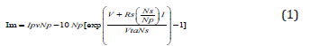
Where, a is the diode ideality constant, Vt is the thermal voltage of the array and can be obtained from the equation (equ.2):
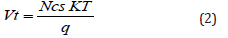
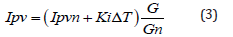
Ncs is the number of cells joined in series, q is the electron charge, K is Boltzmann’s constant, and T is the temperature of the P-N junction in Kelvin’s. Ipv is the photovoltaic Current and can be expressed by (equ.3):
And Io is the reverse leakage current of the diode and can be determined from (equ.4):
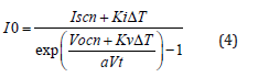
Where: Ipvn is the generated Current at 25oC and 1000W/ m2 (given conditions), Ki, Kv the current and voltage temperature constants sequentially, G is the Irradiance and Gn is the Irradiance at nominal conditions, Iscn, Vocn are the short circuit current and open-circuit voltage respectively at nominal conditions and DT is the difference between the actual and the nominal temperatures in Kelvin’.

Non-Linear characteristics of PV’s
Photovoltaics have non-linear characteristics, where the performance and output power are directly affected with the change of the operating conditions (temperature and solar Irradiance. Figures 2-5 show the effect of varying the temperature and solar Irradiance on PV’s output current, voltage and power.


It is obvious from the preceding figures that the output power of PV’s is directly proportional to the amount of solar Irradiance falling on it and inversely proportional to its temperature. Figures 4 and 5 show that with the change of the temperature and the solar Irradiance the point at which the highest power can be obtained also changes, this means that the array terminal voltage must be varied using DC-DC converters to track the maximum power point. Maximum power point tracking methods will be discussed in detail in next chapter.
Control of MPPT
The maximum power point of any PV changes with the change of the atmospheric conditions (solar Irradiance and temperature). This implies that there is forever one optimum terminal voltage for the PV array to explore at with particular conditions, as shown in (Figure 6) to achieve the maximum power out of it, i.e., improve the array’s efficiency. We can attain peak power-point when the panel is added to a load that matches the characteristic resistance of the PV solar array. This does not occur when the load is connected directly to the array as showed in the below (Figure 6).
From the above illustration, it can be examined that the Maximum Power Point of a direct-connected solar system can be obtained by using a way that mimics a resistance in the output terminals of the PV array. However, the way to obtain the currentvoltage and Power-Voltage characteristics using a changing resistor is not worthwhile in practical applications, and it could be replaced by using the effective impedance of a DC-to-DC Boost converter as in (Figure 7) In this figure, a DC/DC converter has been attached in between a PV array and a Resistive load. That’s way, the input impedance of the DC-to-DC converter becomes the terminal impedance of the PV solar array.
Boost Converter
A boost converter is the simplest sort of switch-mode converter. As the name suggests, it takes the input voltage and hoists it to the desired level. It consists of a Capacitor, a semiconductor switch, a diode, and an Inductor (Figure 8) Also required is a source of a periodic PWM. The biggest desirable advantage of boost converters is their highest efficiency; some of them can show the efficiency of up to 99%.
Working of Boost Converter
When the switching device is open (Figure 9) nothing happens. The output capacitor is charged to the input voltage minus one diode drop. When the switch is on. PWM goes high, switching on the MOSFET. All the current is averted through to the MOSFET through the inductor. The output capacitor stays charged because it can’t discharge through the now back- biased diode. The power source is not spontaneously short- circuited, of course, since the inductor does the current ramp- up relatively slowly. Also, a magnetic field builds up encompassing the inductor. The polarity of the voltage applied across the inductor.
When the MOSFET is switched off, and the current to the inductor stopped abruptly. The primary nature of an inductor is to maintain a smooth current flow; it doesn’t like sudden. It does not prefer the sudden turning off of the Current. It responds to this by producing a large voltage with the opposite polarity of the voltage supplied to it using the energy stored in the magnetic field to maintain that current flow. The inductor now acts as a voltage source in series with the supply voltage. This indicates that the anode of the diode is now at a higher voltage than the cathode and is forward biased. The output capacitor is now charged to a higher voltage than before, which means that we have successfully stepped up a low DC voltage to a higher one (Figure 11).
Average Model for the Boost Converter
Because of the existence of the switches, the boost converter works in two modes. When Switch closed the inductor stores energy and the capacitor release energy. When switch Open, the inductor releases energy, and the capacitor stores energy. As can been seen from the circuit of dc/dc boost converter in (Figure 12) since the inductor, capacitor, switch, and diode do not consume energy at ideal condition, there must exist two fundamental conservation laws between the output and the input.
The first law involves the energy balance, which requires that the input energy equals the output energy (equ.5):
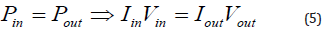
The second law is the charge balance, which means the input charge equal to output charge. Because of the switch, the input current can only provide charge to the output side when the switch is open, and the Time is (1-d) T in one T-period (equ.6):
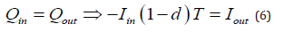
Using the two equations, we can derive the basic relationship between the input voltage and the output voltage (equ.7):
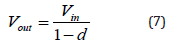
Where d is the duty cycle, which is a positive number less than 1. From the relationship, we can see clearly that Vout>Vin.
The simple model is based on the circuit shown in (Figure 11 & 12) We assume that all components are ideal, that is, no internal resistance in the circuit and the circuit components do not consume any energy. We follow the averaging method and derive the following:
• When the switch is closed, the circuit can be simplified as follows (Figure 13).
Applying KVL in Both loops, we have equations (equ.8&9).

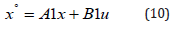
Where IL denotes the Current of the inductor, which equals to Iin and Vc denotes the voltage of the capacitor, which equals to Vout.
Let state variable x1=IL (Iin), x2=Vc (vout), we can rewrite the state equations in state space (equ.10):
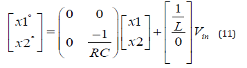
The state-space model will become (equ.11):
• When the switch is open, the simplified circuit is shown below (Figure 14).
Applying KVL in both loops, we have equations (equ.12&13).

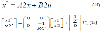
In-state space, the equations are (equ.14&15):
Then the average state-space model is (equ.16):

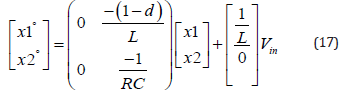
Averaging the state space matrix of two different working modes using the above equations, we get the average model (equ.17):
Literature Review
Relevant state-of-the-art references to the nature of the proposed work are to be cited and discussed. In [1], The IRENA showed the ability of the GCC countries to embark on a diversification strategy to meet growing energy demand and support continued economic and population growth. In this respect, these countries should search for additional renewable sources to maintain their rapid population growth and increasing water desalination are resulting in high energy demand growth, impacting the export levels over the long- term. These dynamic forces have compelled governments to embark on a diversification strategy to meet growing energy demand and support continued economic growth. In [2], the IEA updated most recent five-year renewable energy forecast, published in October 2019. It provides an early analysis of the drivers and challenges and covers renewable capacity additions for all technologies and transport bio fuel production expected during 2020 and 2021. In [3], the author showed an analysis and design of photovoltaic (PV) systems in their three most commonly encountered configurations: systems that feed power directly into the utility grid, stand- alone systems that charge batteries, perhaps with generator back-up, and applications in which the load is directly connected to the PVs as is the case for most water-pumping systems.
In [4], the authors presented a comparative analysis of control methods to extract the maximum power and to track the maximum power point (MPP) from photovoltaic PV) systems under changeable environmental conditions. In [5], the authors mentioned that the maximum power point tracker (MPPT) is a vital device in the photovoltaic (PV) systems because it can increase the generated power considerably. They showed that shading conditions on the PV array generates many peaks in the P-V curve of PV array. Metaheuristic technique like particle swarm optimization (PSO) has the ability to track the global peak (GP) at any operating conditions. In [6], the authors represent the first study that introduces a comprehensive comparison of three efficient maximum power point tracker (MPPT) algorithms that are used to extract the global peak GP of the PV system under both uniform and the partial shading conditions. These MPPT techniques include two metaheuristic techniques, which are cuckoo search optimization (CSO) and particle swarm optimization (PSO) techniques in addition to one conventional MPPT; perturb and observe (P&O). In [7], the authors proposed a new method for the MPPT control of PV systems, which uses one estimate process for every two perturb processes in search for the maximum PV output. In this estimate-perturb-perturb (EPP) method, the perturb process conducts the search over the highly nonlinear PV characteristic, and the estimate process compensates the perturb process for irradiance-changing conditions.
In [8], the authors proposed a detailed comparative survey of four MPPT techniques and concluded that the drawbacks of the three studied methods; P&O, InC and one sensor algorithm, is that at steady state the operating point oscillate around the maximum power point, giving rise to the waste of the output panel’s available energy. Their simulation results show that the proposed fuzzy logic controller (FLC) can provide faster and stable tracking maximum power as compared to the other studied methods. In [9], the authors present a comparative analysis of three MPPT methods which are perturb and observe(P&O), incremental conductance (IC) and particle swarm optimization (PSO) under partially shaded conditions. MATLAB SIMULINK has been used for the analysis and the relevant results are discussed in detail. In [10], the authors studied the behavior of different maximum power point tracking (MPPT) techniques applied to PV systems. They showed some techniques such as hill climbing (HC), incremental conductance (INC), perturb and observe (P&O), and fuzzy logic controller (FLC).
A model of PV module and DC/DC boost converter with the different techniques of MPPTs was simulated using PSIM and Simulink software. The co-simulation was done to take advantage of each program to handle certain part of the system. The response of the different MPPT techniques was evaluated in rapidly changing weather conditions. Their results indicated that, FLC performed best among compared MPPT techniques followed by P&O, INC, and HC MPPT techniques in both dynamic response and steady state in most of the normal operating range. In [11], the authors presented a comparative analysis of three MPPT methods which are perturb and observe (P&O), incremental conductance (IC) and particle swarm optimization (PSO) under partially shaded conditions. MATLAB SIMULINK has been used for the analysis and the relevant results were discussed in detail. In [12], the authors proposed a new method for the MPPT control of PV systems, which uses one estimate process for every two perturb processes in search for the maximum PV output. In this estimate-perturbperturb (EPP) method, the perturb process conducts the search over the highly nonlinear PV characteristic, and the estimate process compensates the perturb process for irradiance-changing conditions. The authored claimed that this method, significantly, improves the tracking accuracy and speed of the MPPT control compared to available methods.
In [13], the authors discussed several techniques regarding their ability to detect the maximum power point, system convergence speed, ease of implementation, efficiency, and cost of implementation. Their work presented a brief review of the main MPPT techniques. Furthermore, this work is gathered from several papers from the last 5 years to present the current state of the art in MPPT technology as well as be a guide for those who want to know more about the new tendencies in this field. General characteristics, advantages, and disadvantages of each paper approached were discussed. In [14], the authors discussed the problem of tracking the global maximum under different conditions and proposed a perturb and observe (P&O) modified algorithm to monitor the maximum power point voltage and triggers a current voltage sweep only when a partial shadow is detected. In [15], the authors modified and re-established a mathematical model of the PV array under PSCs in order to improve and validate the reliable Cuckoo Search Algorithm (CSA) by integrating it with PID (hybrid CSA-PID) to diminish the impact of PSCs problems [16].
MPPT Techniques
Maximum power point tracking techniques are used to extract the maximum power in solar PV system so that most stable and maximum possible power can be transferred from source side to load end. The main aim of MPPT techniques is to hunt the global maximum point. There are various kinds of MPPT techniques for the optimization of solar power and all differ from each other in respect of effectiveness, cost, complexity, speed, and popularity. The scope of this paper comprises of only five MPPT techniques which are discussed below:
Perturb and Observe
The Perturb and Observe (P&O) technique is a fundamental method employed in the pursuit of maximizing power output in photovoltaic (PV) systems, particularly in scenarios where the optimal operating point of the PV array might fluctuate due to changing environmental conditions. P&O operates on a simple yet effective principle: it continuously adjusts the operating parameters of the PV system-typically voltage or current-while monitoring the corresponding change in power output. This adjustment process, known as perturbation, involves small increments or decrements to the operating point.
At each perturbation step, the power output of the PV system is precisely measured or estimated. This measurement serves as the feedback mechanism for the MPPT controller, allowing it to discern whether the perturbation has led to an improvement or degradation in power output. If the observed power output increases following a perturbation, it signifies that the operating point has moved closer to the Maximum Power Point (MPP) on the power-voltage (P-V) curve. Consequently, the controller continues perturbing the system in the same direction, aiming for further optimization of power output.
Conversely, if the power output decreases after a perturbation, it indicates that the operating point has moved away from the MPP. In response, the controller reverses the direction of perturbation, guiding the system towards the optimal operating point. This iterative process of perturbation and observation enables the P&O technique to dynamically track the MPP in real-time, ensuring that the PV system operates at or near its maximum power output under varying environmental conditions.
While P&O is renowned for its simplicity and ease of implementation, it does have its limitations. One notable drawback is its susceptibility to oscillations around the MPP, particularly in scenarios characterized by rapidly changing environmental conditions or partial shading. Additionally, the incremental nature of perturbation in P&O can result in slower convergence to the MPP compared to more advanced MPPT techniques. Nonetheless, the practicality and effectiveness of P&O make it a prevalent choice for MPPT in PV systems across a wide range of applications, from small- scale residential installations to large-scale commercial and utility-scale projects. Its ability to provide real-time adjustments to optimize power output, coupled with its straightforward implementation, cement its status as a cornerstone technique in the realm of PV system optimization (Figure 15).
Incremental Conductance
In the realm of photovoltaic (PV) systems operating under partial shaded conditions, the Incremental Conductance (IC) technique emerges as a sophisticated solution for achieving Maximum Power Point Tracking (MPPT). It functions by continuously refining the system’s operating voltage in response to real-time measurements of voltage (V) and current (I) from the PV array. This dynamic adjustment mechanism enables the system to swiftly adapt to changes in shading conditions, ensuring optimal performance even when parts of the array are shaded. At the core of the IC technique lies the analysis of incremental changes in power (dP) and voltage (dV) at each iteration. These incremental changes serve as pivotal indicators of the system’s proximity to the Maximum Power Point (MPP) on the power-voltage (P-V) curve, guiding the system towards the optimal operating point. Moreover, IncCond compares the ratio of dP/dV to the conductance (G) of the PV system, leveraging this comparison to determine the system’s position relative to the MPP. In the dynamic landscape of partial shaded conditions, where shading patterns may fluctuate rapidly, IC’s real-time adjustment mechanism proves invaluable. It empowers the PV system to swiftly adapt to variations in irradiance levels and shading configurations, ensuring efficient operation and maximizing power output despite shading-induced fluctuations. Unlike simpler MPPT techniques that may struggle to accurately track the MPP under partial shading, IC’s sophisticated algorithms and incremental adjustment strategy enhance precision and reliability in determining the optimal operating point.
By facilitating dynamic optimization of power output based on real-time measurements and analysis, the IC technique drives efficient energy harvesting in PV systems operating under partial shaded conditions. Its ability to continuously refine the system’s operating parameters ensures that the PV system operates at peak efficiency, even in challenging shading scenarios. In summary, the Incremental Conductance technique represents a robust and effective solution for optimizing power output in PV systems under partial shaded conditions, enabling reliable and efficient energy generation in diverse environmental conditions (Figure 16).
Particle Swarm Optimization
Particle Swarm Optimization (PSO) stands as a remarkable algorithmic approach, drawing inspiration from the collective behavior observed in nature, particularly among flocks of birds or schools of fish. When applied to the domain of Maximum Power Point Tracking (MPPT) for photovoltaic (PV) systems under partial shaded conditions, PSO emerges as a powerful tool for dynamically optimizing power output. At its core, PSO orchestrates a population of candidate solutions, termed particles, each representing a potential solution within the solution space. These particles traverse the solution space iteratively, guided by their individual velocities and the collective knowledge shared within the swarm. Through this collective intelligence, PSO enables the swarm to effectively explore the solution space, homing in on the optimal solution over time.
In the realm of MPPT, PSO plays a pivotal role in dynamically adjusting the operating parameters of the PV system to track the elusive Maximum Power Point (MPP) on the power-voltage (P-V) curve. Through iterative updates to their velocities and positions, particles navigate the solution space, homing in on regions of interest where the MPP is likely to reside. This dynamic adjustment mechanism ensures that the PV system remains agile and responsive to changes in shading conditions, thereby maximizing power output even in the presence of partial shading. PSO’s adaptability to partial shaded conditions stems from its inherent ability to dynamically explore the solution space in search of the optimal operating point. By continuously updating particle positions and velocities based on their own experiences and the collective wisdom of the swarm, PSO enables the PV system to swiftly adapt to changes in shading patterns and environmental conditions. This adaptability is crucial for ensuring efficient power generation and maximizing energy harvesting efficiency in challenging scenarios.
Furthermore, PSO strikes a delicate balance between global exploration and local exploitation, thereby avoiding premature convergence to sub optimal solutions. By encouraging exploration of new regions while exploiting promising areas where the MPP may lie, PSO optimally navigates the solution space, ensuring that the PV system tracks the MPP with precision and efficiency. In conclusion, Particle Swarm Optimization (PSO) stands as a sophisticated yet accessible approach to Maximum Power Point Tracking (MPPT) in photovoltaic (PV) systems under partial shaded conditions. Its swarm- based optimization framework, coupled with its adaptability and balance between exploration and exploitation, empowers the PV system to dynamically adjust its operating parameters and maximize power output in the face of changing environmental conditions (Figure 17).


Fuzzy Logic Control (FLC)
Fuzzy Logic Control represents a sophisticated control strategy applied to Maximum Power Point Tracking (MPPT) algorithms in photovoltaic (PV) systems, particularly in scenarios characterized by partial shaded conditions. Here’s a concise overview of its functionality:
FLC leverages the principles of fuzzy logic to enable the PV system to dynamically adjust its operating parameters in response to changing environmental conditions, such as variations in irradiance levels and partial shading. Unlike conventional control methods, which rely on precise mathematical models, FLC allows for the incorporation of imprecise or uncertain information, making it well-suited for real-world applications where environmental conditions are complex and unpredictable. In the context of MPPT under partial shaded conditions, FLC offers several advantages. Firstly, it facilitates adaptive decision-making by considering a range of input variables, including voltage, current, and power measurements from the PV array, as well as environmental parameters like irradiance and temperature. By analyzing these inputs using fuzzy logic rules, FLC can intelligently adjust the operating parameters of the PV system to track the Maximum Power Point (MPP) on the power-voltage (PV) curve. One of the key strengths of FLC is its ability to handle the inherent ambiguity and uncertainty associated with partial shaded conditions. Traditional MPPT algorithms may struggle to accurately track the MPP under varying shading patterns, leading to suboptimal performance and reduced energy harvesting efficiency. However, FLC’s flexible and adaptive nature allows it to navigate these challenges by dynamically adjusting the system’s operating parameters based on real-time inputs and fuzzy logic rules.
Moreover, FLC enables the PV system to respond quickly to changes in shading conditions, ensuring that it remains agile and responsive in dynamic environments. By continuously monitoring and analyzing input variables, FLC can make rapid adjustments to the operating parameters, thereby optimizing power output and maximizing energy harvesting efficiency even in the presence of partial shading. In summary, Fuzzy Logic Control (FLC) represents a powerful and adaptive control strategy for Maximum Power Point Tracking (MPPT) in photovoltaic (PV) systems under partial shaded conditions. Its ability to handle uncertainty and ambiguity, coupled with its adaptability and responsiveness, makes it a valuable tool for optimizing power output and maximizing energy harvesting efficiency in real-world PV applications.
Hybrid Fuzzy Logic Control (FLC) and Perturb & Observe (P&O)
A hybrid approach that combines Fuzzy Logic Control (FLC) with the Perturb and Observe (P&O) technique for Maximum Power Point Tracking (MPPT) in photovoltaic (PV) systems under partial shaded conditions offers a powerful solution to the challenges posed by dynamic and unpredictable shading patterns. This hybrid system leverages the strengths of both FLC and P&O to enhance the efficiency and accuracy of MPPT, thereby maximizing energy harvesting in challenging environments. Fuzzy Logic Control (FLC) provides a flexible and adaptive decision-making framework that can effectively handle the uncertainty and ambiguity inherent in partial shaded conditions. By utilizing linguistic variables and fuzzy logic rules, FLC enables the PV system to make informed decisions based on a combination of input data from sensors monitoring the PV array and environmental parameters such as irradiance and temperature. FLC’s ability to dynamically adjust the system’s operating parameters in response to changing conditions makes it well-suited for real-world applications where shading patterns may vary unpredictably. On the other hand, the Perturb and Observe (P&O) technique offers a simple yet effective method for continuously tracking the Maximum Power Point (MPP) on the power-voltage (P-V) curve. P&O operates by perturbing the operating point of the PV system and observing the resulting change in power output to determine the direction of adjustment needed to approach the MPP. While P&O may struggle to accurately track the MPP under partial shaded conditions due to its reliance on incremental perturbations, it remains a popular choice for MPPT due to its simplicity and ease of implementation.
By combining FLC with P&O, the hybrid MPPT system harnesses the adaptability and intelligence of FLC to dynamically adjust the system’s operating parameters based on real-time input data, while leveraging the simplicity and robustness of P&O for continuous MPP tracking. The FLC component acts as a supervisory controller, guiding the overall decision-making process and providing high-level control based on fuzzy logic rules. Meanwhile, the P&O component operates at a lower level, continuously perturbing the operating point of the PV system and providing feedback to the FLC controller to ensure accurate tracking of the MPP. In summary, the hybrid approach combining Fuzzy Logic Control (FLC) with the Perturb and Observe (P&O) technique for Maximum Power Point Tracking (MPPT) in photovoltaic (PV) systems under partial shaded conditions offers a powerful and adaptive solution to optimize energy harvesting. By synergistically combining the strengths of both FLC and P&O, this hybrid system provides efficient and accurate MPPT, enabling the PV system to operate at or near its maximum power output even in challenging shading conditions.
Results and Discussions
In this section, we will show the design of each technique.
Perturb and Observe
The Simulink model of using Perturb and Observe technique shown below in (Figure 18), the model of PV panel has been used is Trina Solar TSM-250PD05.08, which can produce maximum power 249.86 W, and the number of cells per module is 60(Ncell).
The Results after Simulation: As shown in the (Figure 19 & 20) the voltage output without using MPPT and after using of the technique of P&O technique, the maximum voltage we got it from the P&O technique is 183.2 V which is the Global point, as it shown that the system stable after applying a time of 20 s of simulation since there no noise shown or drop in the voltage. And the comparing of all techniques will be shown at the end of this paper.
Incremental Conductance
For the Simulink model used in Incremental Conductance technique is shown below (Figure 21), the model of PV panel used the same of which was used in previous technique P&O which was Trina Solar TSM-250PD05.08 and the same parameters.
The Results after Simulation: As shown in the (Figure 22 & 23) the voltage output without using MPPT and after using of the technique of Incremental Conductance technique, the maximum voltage we got it from the IC technique is 189.4 V which is the Global point, as it shown that the system stable after applying a time of 20 s of simulation since there no noise shown or drop in the voltage.
Particle Swarm Optimization
For the Simulink model used in Particle Swarm Optimization technique is shown below (Figure 24), the model of PV panel used the same of which was used in previous techniques P&O and IC which was Trina Solar TSM-250PD05.08 and the same parameters.
The results after simulation: As shown in the (Figure 25 & 26) the voltage output without using MPPT and after using of the technique of Particle Swarm Optimization technique, the maximum voltage we got it from the PSO technique is 152.3 V which is the Global point, as it shown that the system un-stable after applying a time of 20 s of simulation in start of simulation.
Fuzzy Logic Control (FLC)
For the Simulink model used in Particle Swarm Optimization technique is shown below (Figure 27), the model of PV panel used the same of which was used in previous techniques P&O, IC and PSO which was Trina Solar TSM- 250PD05.08 and the same parameters.
The Results after Simulation: As shown in the (Figure 28) the voltage output without using MPPT and after using of the technique of Fuzzy Logic Control technique, the maximum voltage we got it from the FLC technique is 56 V which is the Global point, as it shown that the system unstable after applying a time of 6 s of simulation in start of simulation.
Hybrid Fuzzy Logic Control (FLC) and Perturb & Observe (P&O)
For the Simulink model used in Hybrid Fuzzy Logic Control and Perturb & Observe technique is shown below (Figure 29 & 30), the model of PV panel used the same of which was used in previous techniques P&O, IC, PSO and FLC which was Trina Solar TSM-250PD05.08 and the same parameters.
The Results after Simulation: As shown in the (Figure 30 & 31) the voltage output without using MPPT and after using of the technique of Hybrid Fuzzy Logic Control and Perturb & Observe technique, the maximum voltage we got it from the Hybrid FLC and P&O technique is 95 V which is the Global point, as it shown that the system stable after applying a time of 20 s of simulation in start of simulation.
References
- The International Renewable Energy Agency (IRENA) (2016) Renewable Energy Market Analysis for the GCC Region, Masdar City, Abu Dhabi, United Arab Emirates.
- (2020) Renewable Energy Market Update, Outlook for 2020 and 2021, International Energy Agency (IEA).
- Masters GM (2004) Renewable and Efficient Electric Power Systems, 2nd Edn, New Jersey, IEEE Press.
- Pushprajsinh T, Aakashkumar C, Bhargviben P (2016) Comparative analysis of different MPPT techniques for solar system. Int Res J Eng Technol 3(5): 1921-1926.
- Ali M Eltamaly, Mamdooh S Al-Saud, Ahmed GA, Hassan MH Farh (2019) Photovoltaic maximum power point tracking under dynamic partial shading changes by novel adaptive particle swarm optimization strategy, Transactions of the Institute of Measurement and Control.
- Al-Turki F, Abdulrahman A. Al-Shamma’a, Hassan MH Farh (2020) Simulations and dSPACE Real-Time Implementation of Photovoltaic Global Maximum Power Extraction under Partial Shading. Multidi Digital Publishing Institute 12(9): 1-16.
- Shang L, Zhu W, Pengwei L, Guo H (2019) Maximum power point tracking of PV system under partial shading conditions through flower pollination algorithm. Protection & Control Modern Power Syst 3(38).
- Dalila Beriber, Abdelaziz Talha (2013) MPPT Techniques for PV Systems, 4th International Conference on Power Engineering, Energy and Electrical Drives, Powereng-2013 At: Istanbul, Turkey.
- Prachi M, Fani Bhushan S (2020) Performance Analysis of Solar MPPT techniques Under Partial Shading Condition. Int J Eng Res & Technol (IJERT).
- Hegazy Rezk, Ali M Eltamaly (2014) A comprehensive comparison of different MPPT techniques for photovoltaic systems. 2014 Elsevier Ltd.
- Pushprajsinh Thakor, Aakashkumar Chavada, Bhargviben Patel (2016) comparative analysis of different MPPT techniques for solar PV System. Int Res J Eng Technol (IRJET).
- Congwei Liu, Berlin Wu, Ron Cheung (2006) Advanced algorithm for MPPT control of photovoltaic systems, Canadian Solar Buildings Conference Montreal, August p. 20-24.
- Mohammad JM, Victor GMA, Jameel KA, Alex Van den Bossche (2018) Review Different Types of MPPT Techniques for Photovoltaic Systems. International Conference on Sustainable Energy and Environment Sensing (SEES 2018) At: Venue: Fitzwilliam College, University of Cambridge, Cambridge city, UK.
- Oulcaid M, El Fadil H, Yahya A, Giri F (2016) Maximum Power Point Tracking Algorithm for Photovoltaic Systems under Partial Shaded Conditions. 2016 IFAC, International Federation of Automatic Control, FDAC 49(13): 217-222.
- Ibrahim AL-Wesabi, Hassan MH Farh, Abdullah M Al-Shaalan (2022) Cuckoo Search Combined with PID Controller for Maximum Power Extraction of Partially Shaded Photovoltaic System. MPDI energy 15(7): 2513.
- Enrique JM, Andújar JM, Bohórquez MA (2010) A reliable, fast and low-cost maximum power point tracker for photovoltaic applications. Solar Energy 84(1): 79-89.


