


Eddy Current Analysis in the Capacitor Discharge Welding
Moataza A Hindi1 and Mohamed Abu-Aesh2*
1Professor, Electronic Research Institute (ERI), Cairo, Egypt
2Professor, Manufacturing Processes and Materials Science, formerly UOB Bahrain, Bahrain
Submission: May 11, 2023; Published: May 16, 2023
*Corresponding author: Mohamed Abu-Aesh, Professor, Manufacturing Processes and Materials Science, formerly UOB Bahrain, Bahrain
How to cite this article: Moataza A H, Mohamed A-A. Eddy Current Analysis in the Capacitor Discharge Welding. Trends Tech Sci Res. 2023; 6(3): 555689. DOI: 10.19080/TTSR.2023.06.555689
Abstract
The capacitor discharge welding (CDW) process is an autogenous, high-energy density, rapid solidification joining process. It is considered as an electrical resistance welding process since the heat source is the joule effect induced by a capacitive discharge at the welding contact zone. It is an ideal process for joining small parts incorporating dissimilar metals. Potential applications include welding of solderless electrical contacts, welding of thermocouple wire-to-wire or wire-to-plate structure and capacitor discharge (CD) stud welding. Due to the very short time of performing the capacitor discharge; a huge magnetic field is erected around the welded parts, and consequently a huge amount of eddy current is developed. The objective of the present study is to analytically investigate the role of generated eddy current in the CDW process when used in welding two thermocouple wires. A mathematical model is developed to evaluate the intensity of the generated eddy current when the capacitor is being discharged through the two metal wires. This study is counted as the first trial to consider the effect of eddy currents in the capacitor discharge welding process, which may be beneficial in computer simulation work.
Keywords: Capacitor Discharge Welding; Two Thermocouple wires; Eddy Current; Mathematical Analysis
Introduction
Capacitor Discharge Welding (CD Welding) is the fastest form of resistance welding, it utilizes capacitors to deliver the power to the parts. Capacitors are charged with large amounts of energy. Then, the energy is rapidly released into the parts within a few milliseconds. It delivers a laser welded-like joint, meaning that the metallurgy of the steel retains virtually the same characteristics as it did before the CD weld takes place. Like the laser weld, a CD weld delivers a joint that substantially limits surface deformations and spatter. The CD welding process also doesn’t come with the expense of laser welding equipment and the accompanying housing required to make such an operation safe [1].
This procedure has proven invaluable especially in vehicle construction, sheet metal forming, dissimilar metals, decorative metal designs and thermocouple wire-to-wire or wire-to-plate welds. Capacitive discharge welding has many advantages. Weld nugget formation takes place during the first few milli-seconds. Capacitive discharge welders allow extremely fast energy release with large peak currents. More of the energy goes into weld formation and less into heating surrounding material. The heat affected zone, where the properties of the metal have been changed from rapid heating and cooling, is localized to a small area around the weld spot. The quick discharge rate of CD welders also allows electrically and thermally conductive materials, such as copper and aluminum, to be welded. Capacitive welders deliver repeatable welds even during line voltage fluctuations.
Spot welding relies on the principle of metal resistivity to heat and fuse metal. A large current is passed through the work piece. Energy is dissipated due to the metal resistance in the form of heat which melts and fuses weld materials. Due to the fast rate of energy delivery, the eddy currents are likely to be generated in the parts to be welded in un-negligible amounts. The eddy currents are named so because the current looks like eddies or whirlpools. When a conductor is placed in a time-changing magnetic field, the induced current in the conductor is termed as Eddy currents. Eddy current is usually generated in a huge amount at a relatively small time. A lot of literature was carried out to study the CDW process variables to optimize the performance of the process. Moritz Meiners and Rainer Hauenstein [2], in their work presented an in-situ qualitative, indirect current distribution measurement system. They use different current sensors to erect their online measuring system during the process. Nigel Scotchmer [3] in his review paper discussed the rise of CDW applications and advantages. Max-Martin Ketzel, et al. [4] mentioned that in the CDW joining occurs without a welding nugget, but with metal vaporization and linked activation of the surfaces.
A modelling study using ultra high-speed photography by R. D. Wilson, et al. [5] was carried out on the capacitor discharge welding. Their detailed photographic analyses revealed that material is continuously ejected as plasma from the weld area due to induced magnetic forces, rather than having the liquid metal squeezed out of the weld upon contact. S. Chiozzi et al the fatigue lifetime of CDW welded bars of Inconel 718 and TiAl6V4 superalloys [6]. Numerous computer simulation work had been conducted to the CDW process; [7-11] as examples; none of them were found to deal with eddy currents generated in the welded parts. Based on the foregoing review, it would be clear that; among the considerable plentiful literatures carried out on the capacitor discharge welding process, no study was documented about the role of the eddy current in the process. Therefore, the present study is considered to be the first trial to numerically estimate the amount of the eddy current generated during the CDW process.
Problem Formulation

This study concerns the welding of two tips of thermocouple wires to each other using the CDW process. The two wires have the same diameter row and common contact line of length Zo, see Figure 1. The aim of this work is to get a general mathematical formula to estimate the value of the generated eddy current through the wires during the welding process, which can be benefitted in computer simulation studies. Figure 2 shows the application of capacitor discharge circuit through the two wires tips. Charge will cross through the line of contact AB from one wire to another without applying a pressure force on the joint. Charge Q is enough to generate power Em to melt a considerable part of each of the two wires along the line of contact.
Capacitor power given by the equation

Where EC is the power exerted by the capacitor; C is the capacitor capacity; V is the capacitor voltage; is considered equal to the power dissipated in melting the joint Em given by:

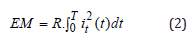
Where R is the contact resistance between the two wires;  is the instantaneous total current flow in the capacitor circuit at a time (t); and T is the total time of the capacitor discharge, Figure 3. Total current
  equals to the summation of the momentum capacitor current
  ,and the value of the generated eddy current Ie , as given by the equation:
Total Current 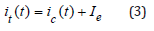
The voltage on the capacitor 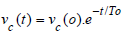
Where:
 = voltage on capacitor C; at time t = 0.
To = time constant = RC (4)
R = Total resistance of the two wires in the region of
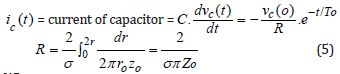
Where:
Zo : interference height where contact resistance between the two wires, Figure 4.
ro : radius of wire, Figure 4.


Eddy Current Analysis
Generated magnetic field lines = H
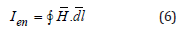
Where:
Ien = enclosed current

Figure 5 shows a representative sketch of the generated magnetic field lines, it is clear from the figure that the magnetic lines are formed in the shape of closed lines.

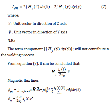
μ : The magnetic constant, the conductor permeability.
This estimation is based on the Biot-Savart law that describes the magnetic flux density propagation B in the distance r caused by an electric current ic . The qualitative magnetic flux density propagation is handled as the primary indicator of the welding quality.
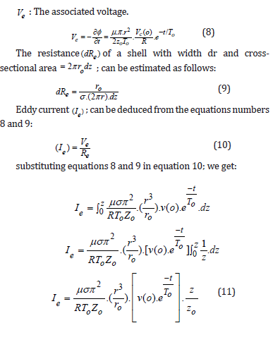
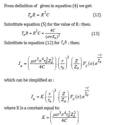
Noting that; the eddy current ; is in the same direction of the capacitor current , and is concentrates at the center of contact length of the two conductors. The eddy current can be expressed another way according to the value of height Z as follows:
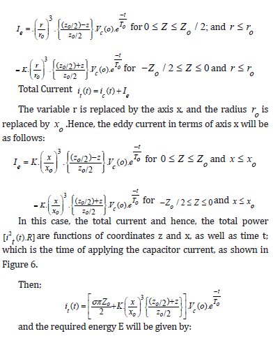
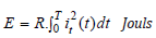
Thus, the required energy is a function of time and dimensions. Some of the generated heat energy will dissipate into the surrounding medium (air), while the majority, which is concentrated at the interface between the two wires will contribute to the welding process.

Conclusion
Among the previous literatures carried out on the CDW process no one documented dealing with the generated eddy current through his work, accordingly it was the aim of the present research to develop the equations to evaluate the eddy current in CDW process as applied on two thermocouple wires junction. However, through the present study the eddy current values are found greater than the original capacitor current, and consequently the generated power. Therefore, it is advised in general for every study of electric source welding process not to neglect the generated eddy current. Through this work the major equations of estimating eddy current concerns CDW process were formulated, and it can be used in further computer simulation study of the process. The generated heat energy at free surfaces will be dissipated to atmosphere by radiation; while the energy will be concentrated at the interface between the two wires.
References
- Dan Davis (2018) Capacitor discharge resistance welding emerges as an important projection welding option. The Fabricator (Issue August 21): 54-55.
- Moritz Meiners and Rainer Hauenstein (2020) Current Distribution Monitoring in Capacitor Discharge welding. 25th IEEE International Conference on Emerging Technologies and Factory Automation (ETFA), Vienna, Austria pp. 447-453.
- Nigel Scotchmer (2015) The Current Rise in the Use of Capacitor Discharge Welding. Welding Journal 94(2): 32-36.
- Max-Martin Ketzel, Martin Hertel, Jörg Zschetzsch, Uwe Füssel (2019) Heat development of the contact area during capacitor discharge welding. Welding in the World 63: 1195-1203.
- Wilson R, Hawk J, Devletian J (1993) Capacitor Discharge Weld Modelling Using Ultra High-Speed Photography. Materials Research Society MRS Online Proceedings Library (OPL) 314: 151-162.
- S Chiozzi, V Dattoma, F Panella (2008) Capacitor discharge welded bars of Inconel 718 and TiAl6V4 super-alloys under fatigue. Materials and Design 29(4): 839-851.
- M Abu-Aesh (2008) Numerical study of thermal effects of electric-discharge through thermocouple wires using finite differences approach. Proceedings of Third IMS International Conference on Applications of Traditional and high-performance materials in harsh environment, American University of Sharjah, UAE, pp. 226-246.
- Xiuzhi Yang, Chunjie Yang, Chunfa Dong, Xinhua Xiao, Wenlin Hua, et al. (2016) Finite Element Simulation of Thermal Field in Double Wire Welding. Journal of Materials Science and Chemical Engineering 4(12): 10-21.
- Johannes Koal, Martin Baumgarten, Stefan Heilmann, Jörg Zschetzsche, Uwe Füssel (2020) Performing an Indirect Coupled Numerical Simulation for Capacitor Discharge Welding of Aluminium Components. Multidisciplinary Digital Publishing Institute MDPI, Processes Journal 8(11): 1330.
- G Casalino, F Panella (2006) Numerical simulation of multi-point capacitor discharge welding of AISI 304 bars. Proc. IMechE Part B Journal of Engineering Manufacture 220(5): 647-655.
- HS Oh, JH Lee, CD Yoo (2007) Simulation of capacitor discharge stud welding process and void formation. Journal of Science and Technology of Welding and Joining 12(3): 274-281.


