


Research on the Control Method of Bottom Hole Pressure for the Deepwater Riserless Mud Recovery System during Shutdown Period
Xin Li1,2 and Jie Zhang1,2*
1State Key Laboratory of Oil and Gas Reservoir Geology and Exploitation, Southwest Petroleum University, China
2Petroleum Engineering School, Southwest Petroleum University, China
Submission: September 24, 2021; Published: October 18, 2021
*Corresponding author: Jie Zhang, State Key Laboratory of Oil and Gas Reservoir Geology and Exploitation, Petroleum Engineering School, Southwest Petroleum University, China
How to cite this article: Xin Li, Jie Zhang. Research on the Control Method of Bottom Hole Pressure for the Deepwater Riserless Mud Recovery System during Shutdown Period. Trends Tech Sci Res. 2021; 5(3): 555661. DOI: 10.19080/TTSR.2021.05.555661
Abstract
In addition to the cyclic drilling, the deepwater drilling also needs to making a connection and round trip to ensure that the drilling operations can reach the predetermined measured depth. Under these two working con-ditions, the drilling pump on the drilling platform will be stopped, and the circulating flow of drilling fluid will also be stopped. However, in the initial stage of circulation of drilling fluid is stopped, affected by the pressure difference, the drilling fluid in the drill string will continue to flow and flow into the annular through the drill bit until the pressure in the drill string and the pressure in the annular reach up to balance, this effect is called the U-tube effect. The occurrence of the U-tube effect will cause continuous changes in bottom hole pressure and increase the risk of drilling operations. Therefore, analyzing and controlling the bottom hole pressure changes during the U-tube effect is essential for improving the safety of deepwater drilling operations. In this paper, by building a mathematical model for the bottom hole pressure calculation of the Riserless Mud Recovery (RMR) system in the initial stage of fluid circulation, the numerical simulation of bottom hole pressure change for the RMR system during this period is carried out, and the change law of bottom hole pressure is analyzed. In the end, we formed a method of bottom hole pressure control suitable for the RMR system during this period.
Keywords:Deepwater drilling; RMR system; Bottom hole pressure; U-tube effect; Safety
Introduction
In recent years, 70% of the world’s significant oil and gas resource discoveries have come from sea areas with a water depth of more than 1,000m [1-3]. At present, the total production of deepwater oil and gas resources has accounted for 80% of the total production of offshore oil and gas resources. Deepwater oil and gas resources have become a critical replacement area for global oil and gas resources. However, due to the peculiarities of the deepwater natural environment and the immaturity of technical equipment, the current conventional offshore drilling technology cannot meet the requirements of deepwater oil and gas resource exploration and development. This problem is mainly reflected in the following three aspects:
a) Narrow safety pressure window. The value between the pore pressure and the fracture pressure of deepwater formations is often relatively close, which requires high precision in the annular pressure control during deepwater drilling operations. If the pressure is not properly controlled, it is straightforward to cause overflow and well kick or even blowout accidents, thereby posing a severe threat to the safety of deepwater drilling operations.
b) The harm of shallow gas. The shallow layers of the deepwater are often accompanied by the flow of shallow water and shallow gas. As the annular pressure is low during the drilling process of the deepwater surface layer, if the pressure is not adequately controlled, shallow fluids will intrude into the annular at a breakneck speed, triggering well kick and even blowout accidents, which poses a severe threat to the safety of deepwater drilling operations.
c) Suspended load of the riser. Suppose conventional offshore drilling technology is used for deepwater drilling operations. In that case, the drilling platform will bear a vast riser suspension load, which will affect the safety of deepwater drilling operations and significantly increase the cost of wells construction.
In order to effectively guarantee the safety of deepwater drilling operations, Norway’s AGR company de-veloped the Riserless Mud Recovery (RMR) System in 2003 [4-7]. RMR system uses a subsea pump lifting device to lift the drilling fluid back to the wellhead in the annular through a small diameter return line to the drilling platform, effectively replacing the traditional offshore drilling. The role of the riser in the technology makes the drilling platform no longer bear the huge riser suspension load, which reduces the requirements for platform construction so that the older generation platform can also be used in deepwater drilling operations [8-10]. Secondly, the RMR system controls the pressure of the subsea pump on the seabed wellhead to be approximately equal to the static pressure of seawater at the working water depth so that the seawater pressure gradient is above the seabed, and the drilling fluid pressure gradient is below the seabed. The control effect can effectively deal with the problem of narrow safety pressure windows for deepwater drilling operations [11- 13].
However, from the application’s perspective, the application depth of the RMR system still does not exceed 1,000m. Therefore, to speed up the use of the RMR system for the exploration and development of deep water oil and gas resources, researchers should proceed from the basic theory to further optimize the design of the RMR system. This paper aims to deal with the bottom hole pressure change caused by the U-tube effect during the shutdown of the drilling pump on the platform of the RMR system. In this research, a physical model of the annular pressure distribution of the RMR system during this period and a mathematical model for calculating the return velocity of annular fluid were built. Secondly, numerical simulations were performed on the return velocity of the annular fluid and changes in bottom hole pressure during this period. Third, we analyze the numerical relationship between the inlet pressure of the subsea pump and the bottom hole pressure during the period. It obtains the co-ordination equation between the two, which forms the control method of the bottom hole pressure of the RMR system during the period.
Physical Model
The physical model of the annular pressure distribution of the RMR system is shown in Figure 1 when the drilling pump stops working.

When the drilling pump stops working, the drilling fluid in the drill string will continue to flow into the annular under the influence of the pressure difference. Therefore, under this working condition, there is a basis for the pressure loss of annular circulation. At this time, the annular pressure distribution of the RMR system is still composed of the subsea pump’s inlet pressure, the annular hydrostatic column pressure, and the annular pressure loss.
Mathematical Model
Assumptions
In order to facilitate the building and solution of the mathematical model, we have made the following rea-sonable assumptions for the mathematical model of the annular pressure calculation of the RMR system under pump shutdown conditions:
a) Drilling fluid is an incompressible fluid
b) Drill string and annular are filled with drilling fluid
c) There is no complicated situation such as leakage and overflow
d) The drill string is centered, regardless of the influence of drill string eccentricity
e) The drilling pump stops immediately, regardless of the impact of water hammer
Mathematical model
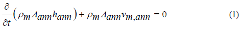
Select the drill string and the annular as the control body, respectively, and the continuity equation of the drilling fluid flow in the annular control body as shown in Equation 1:
The momentum conservation equation of the drilling fluid flow in the annulus control body as shown in Equation 2:

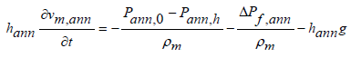
TBy combining Equations (1) and (2) and further sorting out the momentum conservation equation of the drilling fluid flow in the annular control body, The momentum conservation equation can be transformed into the form shown in Equation 3:
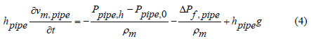
In the same way, the momentum conservation equation of the drilling fluid flow in the drill string control body can be obtained as Equation 4:
Adding Equations (3) and (4), and further finishing, the momentum conservation equation can be further transformed into the form as shown in Equation 5:

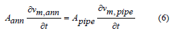
In the assumptions, the drilling fluid is set as an incompressible fluid, the change rate of the volume of the drilling fluid in the annular control body over time is equal to the change rate of the volume of drilling fluid in the drill string control body over time, as shown in Equation 6:
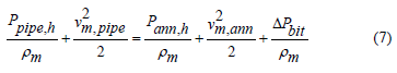
The energy conservation equation of the entire U-tube system is shown in Equation 7:
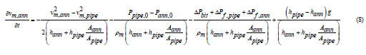
Combining equations (5-7), the equation for calculating the return velocity of the fluid in the annular during the U-tube effect can be obtained as shown in Equation 8.
Initial and boundary conditions
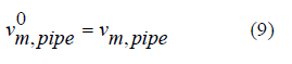
a) The initial velocity of the drilling fluid in the drill string control body is equal to the flow velocity of the drilling fluid in the drill string control body before the platform drilling pump stops working, as shown in Equation 9:
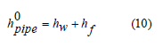
b) At the initial moment, the drill string control body is filled with drilling fluid, as shown in Equation 10:
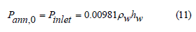
c) After the drilling pump on the platform stops working, keep the inlet pressure of the subsea pump equal to the seawater static pressure at the seabed, as shown in Equation 11:
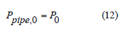
d) After the platform drilling pump stops working, the upper surface pressure of the drill string control body is equal to the atmospheric pressure, as shown in Equation 12:
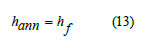
e) The height of the liquid column in the annular control body is the same as the formation depth, as shown in Equation 13:
Model solution
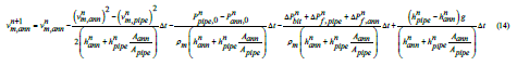
Regardless of the time term or the space term, we use the first-order forward difference method to discretize the calculation equation of the annular fluid return velocity, as shown in Equation 14:
Results and Discussion
Set the displacement of the drilling pump before shutting down as 30 L/s, 35 L/s, 40 L/s, and 45 L/s by combining the calculation equation of fluid return velocity in the annular during the U-tube effect described in section 3, the simulation results as shown in Figure 2.
It can be seen from Figure 2 that the duration of the U-tube effect is about 12.8 min, and the flow rate of the drilling fluid in the annular will gradually decrease to zero as time moves. In addition, the greater the displacement of the platform drilling pump before shutting down, the greater the drilling fluid flow rate in the annular, but the duration of the U-tube effect will not change. The main reasons are as follows:
a) As the pressure in the drill string and the annular gradually becomes balanced, the fluid flow rate in the drill string and the annular will gradually decrease. When the pressures of the two parts reach equilibrium, the fluid in the annular will stop flowing. Therefore, the final flow rate will drop to 0.
b) The more significant the displacement of the platform drilling pump before shutting down, the greater the initial velocity of the drilling fluid flow in the drill string. The larger the displacement of the drilling fluid into the annular, the greater the flow rate of the drilling fluid in the annular.
c) The more significant the displacement of the platform drilling pump before shutting down, the greater the momentum when the drilling fluid flows, but the corresponding frictional resistance will also be more significant. Therefore, according to the law of conservation of momentum, the duration of the U-tube effect will not change significantly.

In order to propose a corresponding bottom hole pressure control method, we further analyzed and calculated the bottom hole pressure change trend of the RMR system during the period based on the above simulation results. The calculation results are shown in Figure 3.

It can be seen from Figure 3 that the greater the displacement of the platform drilling pump before shutting down, the greater the bottom hole pressure of the RMR system during the U-tube effect period, and it will eventually stabilize to the same pressure value. Second, the bottom hole pressure during the U-tube effect is lower than during cyclic drilling. The main reasons are:
a) The more significant the displacement of the drilling pump before shutting down, the greater the velocity at which the drilling fluid in the drill string enters the annular, and the greater the annular pressure loss, so the bottom hole pressure rises. When the pressure in the drill string and the annular is rebalanced, the drilling fluid in the drill string no longer flows into the annular. At this time, the pressure in the annular is only composed of the inlet pressure of the subsea pump and the pressure of the hydrostatic column in the annular so that the bottom hole pressure will be stable at the same pressure value.
b) During the U-tube effect of the RMR system, the return velocity of the drilling fluid in the annular will continue to decrease, and the pressure loss in the annular will also continue to decrease accordingly. Therefore, the bottom hole pressure of the RMR system during the U-tube effect is lower than during cyclic drilling.
c) During the U-tube effect of the RMR system, since no drill cuttings are generated, the fluid flow in the annular changes from a solid-liquid two-phase flow during cyclic drilling to a singlephase flow. The hydrostatic column pressure in the annular is only determined by the density of the drilling fluid. This condition also causes the bottom hole pressure of the RMR system to be lower than during cyclic drilling.
In order to keep the bottom hole pressure of the RMR system constant during the U-tube effect, the inlet pressure of the subsea pump can be adjusted in real-time to temporarily compensate for the decrease in the annulus pressure to ensure the constant bottom hole pressure during this period. Figure 4 shows the relationship between the inlet pressure of the subsea pump and the bottom hole pressure under different drilling pump displacements before shutting down.
Through the numerical fitting analysis of the relationship between the inlet pressure of the subsea pump and the bottom hole pressure in Figure 4, it can be obtained that the coordination relationship between the two roughly satisfies the Equation 15 while keeping the bottom hole pressure of the RMR system constant.
The bottom hole pressure control method for the RMR system we formed during the U-tube effect is as follows:
a) Set the control reference value of the bottom hole pressure at the initial moment as the formation pore pressure.
b) According to the set value, adjust the displacement of the platform drilling pump before shutting down.
c) Adjust the inlet pressure of the subsea pump in real-time according to the bottom hole pressure value in combination with Equation 15.
d) Judge whether the bottom hole pressure is equal to the formation pressure.
e) After the drilling pump is restarted, adjust the inlet pressure of the subsea pump to be equal to the static seawater pressure.

Conclusion
a) The greater the displacement of the drilling pump on the platform before shutting down, the greater the return velocity of the fluid in the annular of the RMR system during the U-tube effect, but the duration of the U-tube effect will not change.
b) The greater the displacement of the drilling pump on the platform before shutting down, the greater the bottom hole pressure of the RMR system during the U-tube effect, and it will eventually stabilize to the same pressure value.
c) The inlet pressure of the subsea pump can be adjusted to temporarily compensate for the decrease in the annular pressure of the RMR system during the U-tube effect. The corresponding relationship between the inlet pressure of the subsea pump and the bottom hole pressure satisfies the Equation 15.
Acknowledgment
The authors thank the financial supports from the National Natural Science Foundation of China (No. 51274168), the National Key R&D Program of China (No. 2018YFC0310202), and the Southwest Petroleum University Graduate Research and Innovation Fund Key Program (No. 2020CXZD30).
References
- Zhang J, Li X, Tang, X, Luo W (2019) Establishment and Analysis of Temperature Field of Riserless Mud Recovery System. Oil Gas Sci Technol 74(19): 1-9.
- Li X, Zhang J, Tang X, Mao GZ, Wang PG (2020) Study on Wellbore Temperature of Riserless Mud Recovery System by CFD Approach and Numerical Calculation. Petroleum 6(2): 163-169.
- Li X, Zhang J, Zhao HY, Zhang M, Sun XF, et al. (2020) Study on Lifting Efficiency of Cuttings in Return Line of Riserless Mud Recovery System. The 9th International Conference on Informatics, Envi-ronment, Energy and Applications, p. 20-26.
- Li X, Zhang J, Li CN, Li B, Zhao HY, et al. (2021) Variation characteristics of coal-rock mechanical properties under varying temperature conditions for Shanxi Linfen coalbed methane well in China. Journal of Petroleum Exploration and Production Technology 11(7): 2905-2915.
- Li X, Zhang J, Wu CJ, Hong TY, Zheng YD, et al. (2021) Experimental Research on the Effect of Ultrasonic Waves on the Adsorption, Desorption, and Seepage Characteristics of Shale Gas. ACS Omega 6(26): 17002-17018.
- Li X, Zhang J, Li RX, Qi Q, Zheng YD, et al. (2021) Numerical Simulation Research on Improvement Effect of Ultrasonic Waves on Seepage Characteristics of Coalbed Methane Reservoir. Energies 14(15): 4605.
- Li X, Zhang J, Zheng YD, Li CN, Li ZL, et al. (2021) Experimental Research and Numerical Analysis of the Attenuation Law of Ultrasound Propagating in Shale. Journal of Physics Conference Series 1980(1): 34-40.
- Li X, Zhang J, Li CN, Chen WL, He JB, et al. (2021) Characteristic Law of Borehole Deformation Induced by the Temperature Change in the Surrounding Rock of Deep Coalbed Methane Well. Journal of Energy Resources Technology 144(6): 063003.
- Zhang J, Zhao ZP, Li X, Zheng YD, Li CN, et al. (2021) Research on the mechanism of the influence of flooding on the killing of empty wells. Journal of Petroleum Exploration and Production Technology 11(9): 3751-3598.
- Godhavn J (2010) Control requirements for automatic managed pressure drilling system. SPE Drill Complet 25(3): 336-345.
- Marcellinus A, Ojinnaka S, Joseph JB (2018) Full-course drilling model for well monitoring and stochastic estimation of kick. Journal of Petroleum Science and Engineering 166(4): 33-43.
- Rezk R (2013) Safe and Clean Marine Drilling with Implementation of “Riserless Mud Recovery Technolo-gy-RMR”. SPE Arctic and Extreme Environments Conference.
- Stave R, Nordas P, Fossli B (2014) Safe and Efficient Tophole Drilling using Riserless Mud Recovery and Managed Pressure Cementing. Offshore Technology Conference.


