Special Design of Heavy Mass Base Foundations Methods in Rocks and Clay Soil Sub-Surfaces Techniques
Vijayvenkatesh Chandrasekaran*
Department of civil and engineering, St. Josephs college of Engineering and Technology, India
Submission: June 01, 2018; Published: July 05, 2018
*Corresponding author: Vijayvenkatesh Chandrasekaran, Department of civil and engineering, St. Josephs college of Engineering and Technology, Thanjavur-613403, India, Tel: 7502551314; Email: ramathutham@gmail.com
How to cite this article: Vijayvenkatesh C. Special Design of Heavy Mass Base Foundations Methods in Rocks and Clay Soil Sub-Surfaces Techniques. Trends Tech Sci Res. 2018; 2(3): 555589. DOI: 10.19080/TTSR.2018.02.555589
Abstract
These paper constitute consists of parts of foundations design of under and sub structural plans. First of all, foundations are the lowest artificially prepared parts of the structures which are in direct contact with ground surfaces are known as Foundations. But its different categories for the zones of ground ability. Most of the foundations are normal status and load distribution neutralizations in normal bearing values of depends upon the soils. But rocks and clay soil zones areas not suited for normal sub structural design methods. Its followed by high precious design sections and execute the better results. And followed design methods is used for high precious focus in mountain and steep constructions, Water-bearing area, it's also better suitable in heavy constructions mass base foundation methods of high rise buildings system.
Keywords: Rock boring; Grout hole; Anchorage bolting systems; Mass base trapezoidal foundations designs
Introduction
The soil ground on which the foundation's rest is that foundation bed or foundation soil and it ultimate bearing of loads and interact with the foundations of structure [1]. Case study and objective of foundations to distribute the total load coming on the structure on a large area as well as great supported on the structure and required enough stability of the structures against various disturbing forces such eradicated climatic barriers. And to prepare the level of surfaces for concreting and masonry work. Inspections of sites its desirable to recognize the site of works and inspect them carefully from the viewpoints of foundation details [2]. And to analyse the nature and thickness of strata of soil may be estimated by studying the excavation detail of nearby constructionor by examining the open side of a nearby well etc. the general inspection of site of works serves of a good guide for determining the type of foundation to be adopted for the proposed work and in addition, it helps in getting the data with respects to used for design purposes. That following data is used for items. The behaviour of ground due to variation in depth of water table, Capacity of percolation of storm water at the site, nature of the soil and visual analyzation, movement of ground due to any reason [3]. Examinations of grounds, The load of the structure is ultimately transferred to the soil it becomes, therefore, essential to know the quality and thickness of soil undergrounds and such as a study would assist in selecting an economical but safe design for the foundation of the structure [4].
Methods
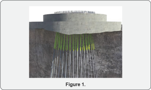
That Figure 1& 2 represents the special form of trapezoidal foundation mass basements and deep grout anchorage systems. Its, essentially high interlock grip effect with substructures to superstructures. Its typically handled in 50mm deep boreholes and required depth essentially carrying out of deep boring for big important engineering structure [5]. Its methods anchor bolts rock concrete grout such as the addition to the of the ability of superstructure, importance is to be given to various other factors such as the same application in dams. Boring is followed by the 2-methods, Percussions boring machines and core rotary equipment.
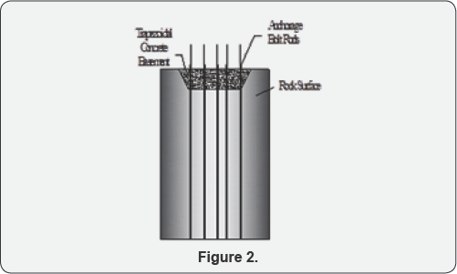
In this process, the heavy cutting tool is dropped into the ground by means of a series of blows. That method used to prefer in a semi layer hard rock soil and rock layer zones areas. The broken rock material is brought to the ground by adding water into the core and then the paste is lifted to the ground. The material thus obtained is made dry and it is then examined. The percolations of boring machines is very much use of hard rock zones areas [6], And another condition it is very old method better results values and created a large number of vibrations in heavy blowing. Some problems cracking in nearest structures.
Core and rotary drilling machines
In this process, a hollow tube is driven by rotary motion which cuts a solid core. Water is used to facilitate the cutting process [7], That machines can be used either for soft or hard rocks materials. If the tube passes through a hard material, the core is retained and this has to be cut at the bottom and lifted up [8], This is done by pouring sand at the inner side between the core and inner surface of the tube and then the tube is slightly rotated [9], The core is then broken and caught in the tube along with sand and it is lifted up.
Anchorage bolts and concrete systems assembly
After the 25 to 50mm boreholes and provided the bolting anchorage rods used in the rock in required foundations depths [10], And its mostly used in peikko anchorage systems in better in rock foundation methods. At one head of fixed bolt head into the provided in required depth of rock. And after pouring the settling concrete. And setting properly and to tighten the top of the bolting rod. Its better frictions joints of the basement and foundations to substructures levels [10]. Referred the design approach of followed in ASTM, A36, A307 (Grade B), A325, A449 and A687 [11]. Used in concrete. The Bolt threads at the surrounded closing stages of apiece threaded steel bar are stake at top and bottom places below the grave curse nut. That concrete is placed in well-hardened status in 14- days after to tightening to bolt rotation.
Rock grouting
Boreholes in sufficient number are driven in the ground. The concrete grout is then forced under pressure through these bore holes [12]. These any of crack fissures of the rock are thus filled up, resulting in the increased of bearing power of rock. Its process aided to some other chemical treatment certain chemicals are used in place of cement grout to solidify the but this process is adopted by small-scale construction is costly it is only in case of important building.
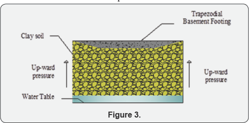
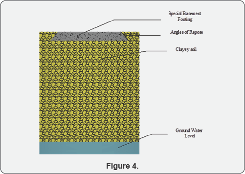
Figure 3 & 4 Represents the Mass Trapezoidal basement foundations on clay and clayey soils. Clay and clayey soil is a partial work in cohesive and cohesive less in seasonal climatic conditions [13]. It is highly preferred in irrigations systems and not preferred in shallow foundations. That foundation is broadly shallow spread over the construction site area. Its possibly to constructed foundations are termed trapezoidal basement foundation. In such spread case of overall in a raft. And to assemble the assembly structural column sections. Its high economical evaluation in compared to other pile foundations better load transparent in cohesive soils.
Design criteria of special mass basement footing
The total load to be transmitted by the walls or columns to the foundation beds. The results of foundation pits and the corresponding bearing capacity of each stratum of soil [14]. It respects to 2 aspects.
Width of foundations
A width of the special footing basement is decided by adopting the following rules:
If no footing is to be provided to the constructional site area, it will provide the assumption columns should be provided in required depth and equal areas as shown in Figure 1. The total load including dead load and wind load coming on the columns per meter length at are in case of heavy construction the load aspects in the centre of the basement, it worked out. Then the width of the foundation is obtained from the following relation.
a. For column,
The width of foundation basement = {Total load per meter length /allowable bearing capacity of the soil}
b. For piers,
The width of foundations basement = {Total load on the pier/allowable bearing capacity of the soil}
Usually, the wall, columns, piers are given with of basements connects to plinth level. By adding the width of offset of concrete, the total width of foundation can be obtained. And this width of increased bearing pressure is vice versa to increase Table 1.
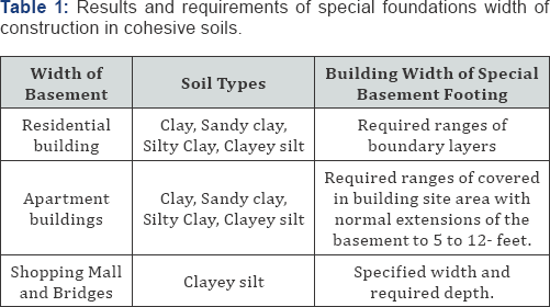
Depth of foundations
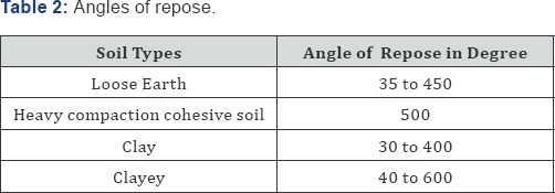
As a general rule, all the heavy mass base foundation should be taken to a minimum depth of 80 cm below natural ground level unless the hard soil is available within 80 cm. the total load is transferred to the soil per square meter can be worked out and after the study of the results of the trial pits, the foundation should be taken to such a depth at which the soil has an allowable bearing capacity greater than the value. The depth of foundations can also be obtained by drawing the lines of angles 450 and 600 as shown in Table 2. Rafting methods are increased the bearing power of soil becomes very useful when the load coming on the soil is practically uniform while soil yielding nature.
Conclusion
It is a final conclusion of the paper is special mass base heavy foundation technique is followed by critical soil and Rock category suitable preferred of the important structure. Such structure has to be designed for heavy loads and ordinary methods of providing foundations may not be suitable for structure. In that such case, methods handling in special heavy basement footings is resisted to heavy loads and increased the bearing capacity pressure of soil. That concept of a method of increasing the bearing power of clayey soil becomes useful, especially when there is used in a ground floor structure.
References
- Meyerhof GG, Hanna AM (1978) Ultimate bearing capacity of foundations on layered soils under inclined load. Canadian Geotechnical Journal 15(4): 565-572.
- Gambatese JA, Behm M, Rajendran S (2008) Design's role in construction accident causality and prevention: Perspectives from an expert panel. Safety science 46(4): 675-691.
- Shougrakpam S, Sarkar R, Dutta S (2010) An experimental investigation to characterise soil macroporosity under different land use and land covers of northeast India. Journal of Earth System Science 119(5): 655674.
- Bieniawski ZT (1989) Engineering rock mass classifications: a complete manual for engineers and geologists in mining, civil, and petroleum engineering. John Wiley & Sons, United States, p. 251.
- Pusch R, Ramqvist G, Kasbohm J, Knutsson S, Mohammed MH (2012) The concept of highly radioactive waste (HLW) disposal in very deep boreholes in a new perspective. Journal of Earth Sciences and Geotechnical Engineering 2(3): 1-24.
- Harris CS, Varley PM, Warren CD, Hart MB (Eds.) (1996) Engineering geology of the Channel Tunnel. Thomas Telford.
- Banholzer WF, Anthony TR, Gilmore RS, Siemers PA, McCloskey JC (1994) U.S. Patent No. 5,363,556. Washington, DC: U.S. Patent and Trademark Office.
- Jimeno EL, Jimino CL, Carcedo A (1995) Drilling and blasting of rocks. CRC Press, United States.
- Lade PV (1981) Torsion shear apparatus for soil testing. In Laboratory shear strength of soil. ASTM International, United States.
- Bruce DA, Jewell RA (1986) Soil nailing: application and practice-part 1. Ground Engineering 19(8): 10-15.
- Wells M (2005) Skyscrapers: Structure and design. Laurence King Publishing, United Kingdom.
- Shipp JG, Haninger ER (1983) Design of headed anchor bolts. American Institute of Steel Construction, United States.
- Karol RH (2003) Chemical grouting and soil stabilization, revised and expanded (Vol. 12). Crc Press.
- Regüés D, Pardini G, Gallart F (1995) Regolith behaviour and physical conditions in a badland area at Vallcebre, Eastern Pyrenees. Catena


