Troubleshooting Identification and Upset Conditions Effect of LNG Plant
Mohamed Halafawi1* , Ayham Mhanna2, Mirna Charif3 and Lazăr Avram1
1Drilling and production Engineering, Romania
2Petrochemical, Petroleum-Gas University of Romania, Romania
3Chemical Engineering, Petroleum-Gas University of Romania, Romania
Submission: June 29, 2019; Published: November 01, 2019
*Corresponding author: Mohamed Halafawi, Drilling and production Engineering, Romania
How to cite this article: Mohamed Halafawi, Ayham Mhanna, Mirna Charif, Lazăr Avram. Troubleshooting Identification and Upset Conditions Effect of LNG Plant. Recent Adv Petrochem Sci. 2018; 6(5): 555697. DOI: 10.19080/RAPSCI.2019.06.555697
Abstract
The Liquefied Natural Gas (LNG) plant has a lot of troubleshooting and upset conditions which appear during operating processing units for petroleum fields. These undesirable situations and obstacles have a great influence on plant performance and production. Therefore, the main objective of this paper is to identify LNG plant troubleshooting and determine its upset conditions. A full description for troubleshooting produced from operating plant units, which are not presented in operating manuals, is categorized. Additionally, the effect of upset conditions on each unit is presented. In order to solve these troubleshooting and disturbed situations, the best remedial and corrective actions are then proposed. The best operating practice is also suggested. A real case study of LNG plant is done for the main 19 units of the plant: U01, U02, U07, U08, U12, U13, U14, U15, U16, U18, U51, U55, U56, U58, U63, U71, and U76. It is found that the upset conditions effect is loss of electrical power, loss of instrument air, loss of gas feed, and troubleshooting. Most of the LNG units are suffering from disturbed conditions and troubleshooting during operation except U01, U02, U07, U65, and U71.
Keywords: LNG plant Troubleshooting Good operating practice Upset conditions
Introduction
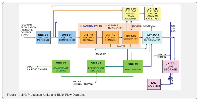
LNG is an acronym for Liquefied Natural Gas which is basically constituted of Methane (C1) supplemented by Ethane (C2), Propane (C3), and Butane (C4). LNG is an odorless, nontoxic, colorless, flammable, noncorrosive cryogenic liquid at normal atmospheric pressure, liquefied at -1610C at 1.0 bar, owned vapor heavier than air < -1300C, cold burned when in contact, and expanded 600 x from liquid to gaseous [1-4]. The boiling point of LNG alters with its composition, typically –162C (–259 F). The LNG density typically ranges between 430 kg/ m3 and 470 kg/m3 (3.5 to 4 lb/US gal), which is less than half the water density. However, natural gas released from the LNG may produce asphyxiation due to O2 lack in an unventilated, closed area, and may be ignited if combined with the right concentrations of air. Additionally, when LNG is released in an enclosed space or low spot, it will tend to displace air, causing the area hazardous for breathing [1,3]. In order to make LNG, the natural gas, which is coming from feed gas supply of gas or oil wells, should processed through several separation and petrochemical processes’ units in an LNG plant (Figure 1). LNG plants are classified into large base load, peak-shaving, and small- to medium-scale plants depending on their sizes and functions. LNG plants of petroleum fields are extensively used all over the world. However, majority of the base load plants are positioned in large gas reservoirs in Asia, Australia, the Middle East, and West Africa and are mega projects [1,4]. These plants provide natural gas as LNG from the natural gas fields to the remote consumer nations. However, all kinds of LNG plants have a lot of troubleshooting and problems during operating plants. These troubleshooting and problems, which occurred in plant units, lead to reduce the plant profitability, safety, production and performance.
Moreover, they may cause hazards to environment, personnel, and production. LNG plants may certainly lose their integrity due some of these troubleshooting. Some of these problems and troubleshooting are previously presented stated by vendors and unit operating manual. In addition to those presented by vendors or unit operating manual, few authors, published articles, andtextbooks have already discussed troubleshooting and unset conditions effect of LNG plants in general or for a specific unit. However, there are many upset conditions and troubleshooting occurred during operating LNG plants which are not presented or discussed previously. Consequently, the demand for a collective study to identify upset conditions effect and their remedial actions, troubleshooting causes and their corrective actions, and good practice operating guidelines for LNG plant became extensively desirable. Therefore, the aim of this article is to identify and review LNG plant troubleshooting and upset conditions effect during operating. In order to maximize the profit contribution of plant processing facilities, optimize units’ performance, reduce maintenance costs, and ascertain the integrity of processing units, remedial actions and corrective procedures are proposed.
LNG Plant Description and Overview
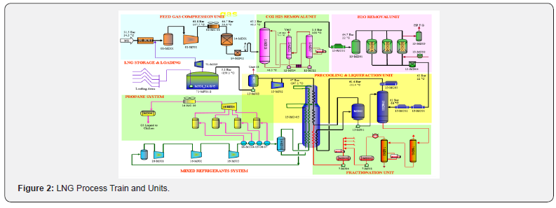
The LNG plant facilities, located on the Mediterranean coast - sea port area, is designed to receive 5.93 b cm/year inlet natural gas, to handle 487 ton LNG/hour – 4.26 million ton LNG/year as a production capacity, to provide 55,000 m3 – 180,000 m3 of LNG Cargo Ships as a Jetty berthing capacity, to store 2 x 135,000 m3 of LNG as a storage capacity for 7-8 days of production, to have performance efficiency of 87.7%, to be available 338 days/ year (92.6% of year), to reach 45% Turn Down Ratio using APCI technology, 295 Air Coolers as a cooling media, gas supply from sea gas grid and completely self-sufficient in utilities such as Power Generator (5 x 22.5 MW).The plant takes the natural gas from the gas grid at about 35oC and 33 bara and produce and store LNG at about -161oC and 1.1 bara. The LNG plant handles either lean gas having a low heavy hydrocarbon content or “rich” gas having a significant heavy hydrocarbon content. Feed gas arrives at the plant from the offshore gas network. The feed gas is metered by one of two ultrasonic flow meters 01-FT-3001 and 01-FT-3002. It is then compressed to 68bara, using a motor driven centrifugal compressor (01-MJ01), to feed the LNG train. The LNG plant has a number of processing utility and offsite units. The flow diagram of the LNG units is shown in (Figure 2).
As a result, a phenomenon occurs in which new knowledge eliminates the so far used method. Eliminating does not mean that old knowledge disappears in a literal way, on the contrary it may still co-exist and be exploited, but it becomes obsolete and ineffective. Acquired knowledge becomes a contribution to new technical solutions, which in turn stimulate further diffusion of new knowledge. The example could be the development of renewable energy technologies which replace those previously used, traditional energy resources. Therefore, diffusion described by Griliches as true, occurring when the innovation buyer performs its reconstruction, and then by expanding the resources of own knowledge, the buyer constructs successive solutions that are a source of continuous productivity growth [7].
Although the diffusion depends on the type of knowledge and its characteristic connections, it always determines its progress and such a change that will match it to the requirements of specific entities or their communities. If the inventor decides to apply for patent protection, the diffusion of knowledge, in this case of explicit knowledge, may occur before the commercialization of the invention. It is the so-called technical quantified knowledge. In the case of patents, the diffusion of technical knowledge is possible thanks to the mapping by means of specific technical parameters. Technical parameters are certain characteristic values that can be measured directly or using mathematical formulas with specific variables [8].
Upset Conditions Effect and Troubleshooting of LNG Plant
Plant feed conditioning:
Upset Conditions Effect (UCE) on the plant feed conditioning of LNG plant include loss of electrical power, loss of instrument air, loss of feed gas and unit troubleshooting
Loss of electrical power:
Loss of power to the compressor 01-MJ01 will trip the motor and will result in a train shutdown. Loss of power to the after cooler 01-MC01 will not necessarily trip the Feed Gas Compressor but it is likely the Feed Gas Compressor throughput will have to be reduced.
Loss of instrument air:
Loss of instrument air will cause control valves to fail to their safe position. Consequences of the loss of instrument air for the major control and isolation valves are given: Valves 01-ESDV-1000, 01-ESDV-1012, 01-ESDV-1035 will fail close, and Valves 01-BDV1036, 01-UV1016, 01-BDV1040, 01-XV1063 will fail open.
Loss of feed gas:
Loss of natural gas feed will result in a total shutdown of the system. The Feed Gas Compressor can remain on full recycle until the conditions are stabilized and the gas flow is re-established. (Depending on the nature of the trip). It maybe necessary to shut down the compressor if the interruption is lengthy.
Trouble shooting:
No observed troubleshooting during operation other than that stated by vendor or existed in operating manuals.
Acid gas removal (common facilities)
Acid gas removal unit of LNG plant is affected by certain upset conditions during operating such as:
Loss of electrical power:
A general loss of power causes the pumps to trip and would result in a loss of reflux to the columns, a high level in the bottom of the Depentanizer 07-MD09, and a high level in the LPG Reinjection Drum 07-MD08. The system is safeguarded by low flow alarms on the discharge of the reflux pumps, and high-level alarms in the Depentanizer, and LPG Reinjection Drum. When the MCC indicates both LPG Reinjection Pumps 07-MJ04/-A are stopped, Interlock I-720 will close 15- ESDV-1114 the LPG Reinjection into the MCHE 15-MC05, and 15-ESDV-1223, the LPG + Pentane Reinjection upstream of the Scrub Column Overhead Condenser, 15-MC03. For individual scenarios the particular operating mode determines which of these ESDVs are actioned, depending upon the feed gas case. The Fractionation Refrigeration Package 07-ML01 will shut down. Loss of power may eventually lead to a Unit 07 shutdown.Following a Unit shutdown all the liquid from the Scrub Column, 15-MD01 will be required to be manually routed to Unit 65 for disposal.
Loss of instrument air:
The plant will continue to operate satisfactorily until the air pressure reduces significantly. This reduction in instrument air pressure will force all control valves to manual and fail to their safe position. This will rapidly cause interruption of the main process flow. NGL feed to the Fractionation Unit will cease, and all the liquid will remain in the Scrub Column, 15-MD01. Feed in the Fractionation Unit will be effectively isolated in the columns, under pressure. In addition, hot oil flow to the reboilers will cease, and MP, LP propane flow from the Fractionation Refrigeration Package 07-ML01 will be lost. Loss of instrument air over a prolonged period may resultin a de-pressuring of the entire plant, as air pressure is lost to blowdown valves. Although this is an extremely rare event the operator should take the necessary precautions to depressurize the Unit in advance of an entire loss of instrument air.
Loss of Feed:
When Unit 07 is required to operate it is an integral part of the LNG Train. Loss of natural gas feed to the plant will result in a total shutdown of the LNG train. Loss of feed to the Fractionation Unit 07 will result in a high liquid level accumulating in the Scrub Column 15-MD01. This is safeguarded by a high-level alarm 15-LIC 1011. Reduced flows will feed the downstream columns, and the Unit will go into full recycle. All column bottoms FVs will close. The overhead vapor flows will reduce to maintain column pressure. As column levels fall the vapor breakthrough protection interlocks are initiated on the columns: Deethanizer I-0710; Depolarizer I-0740, Debutanizer I-0760 and Depentanizer I-0765. A low liquid level, sensed in the LPG Reinjection Drum 07-MD08, or 07-ESDV1209 positioned less than 80% open, will initiate Interlock I-0780, LPG Reinjection Backflow Protection. This ensures the LPG Reinjection Pumps 07-MJ04/-A are tripped and isolates the drum via Interlock I-0720. Since levels will fall in the reflux drums and product purity may be affected, a controlled manual shutdown of the Unit should be initiated if the feed cannot be restored.
Loss of hot oil:
Hot Oil, as Shell Hermia ‘B’, supplies the reboiling capacity of the Unit. Loss of this heating medium will effectively stop all fractionation of the feed, and ultimately the bottom purity. Therefore, a controlled manual Unit 07 shutdown should be initiated to stop the feed flow forward.
Loss of cooling water:
Tempered water is provided as cooling water in the lube oil coolers for the Fractionation Refrigeration Package 07-ML01 compressors. Since this package supplies the propane coolant to the LPG Reinjection Cooler 07- MC09, and the Deethaniser Condenser 07-MC03, these vapors will fail to be sufficiently condensed. To stabilize the plant a manual shutdown should be initiated.
Hot oil system (Common facilities)
Hot oil system has troubleshooting due to low discharge pressure problem at 08-PG-1001 (unit 08), 18-PG-1009/1011 (unit 18), and 58-PG-1010/1011 (unit 58) because of air in system (pump gassed up), dirty suction strainer, and pump wear rings worn. The corrective actions are to vent pump, change over pumps and clean strainer, and change over pumps to check respectively.
Acid gas removal (common facilities)
UCE of hot oil system in LNG plant is appeared in power loss, air instrument loss, and troubleshooting. They are explained as follows
Loss of electrical power:
Loss of electric power will trip the motor of the hot oil pump 08-MJ02 and it will shut the pump down. For unit 18, hot oil circulation will cease and restart the system as per the normal start procedure.
Loss of instrument air:
Since there are no pneumatic control systems on this unit and pressure, level measurements are electronic; loss of instrument air should not affect the system. For unit 18 and 58, will cease, loss of instrument air will activate the hot oil furnace trip as a result of the closure of fuel gas isolation valves. The flow of hot oil through the unit will cease, and all the control valves will go to the failsafe position.
Loss of feed or flow:
Not Applicable but for unit 18, 18-MJ01 or 18-MJ01A failure. The spare pump will start up automatically. For unit 58, loss of Fuel Gas will result in Hot Oil furnace, 58- MB01 trip due to flame out of burners. When fuel gas supplies are re-established, re-start the furnace as per the normal startup procedure.
Trouble shooting:
Hot oil system has troubleshooting due to low discharge pressure problem at 08-PG-1001 (unit 08), 18-PG-1009/1011 (unit 18), and 58-PG-1010/1011 (unit 58) because of air in system (pump gassed up), dirty suction strainer, and pump wear rings worn. The corrective actions are to vent pump, change over pumps and clean strainer, and change over pumps to check respectively.
Acid gas removal
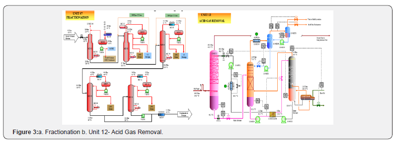
UCE in LNG Plant that appeared in unit 12 (Figure 3b) Includes
Loss of electrical power:
In the event of loss of electrical power, the train emergency shut down interlocks will ensure the safe shut down of unit 12 when Manual ESD HS - 1000 is operated. The emergency Diesel Generator, however, provides emergency lightening and other essential facilities. Load shedding is provided to cater for transient disturbances.
Loss of instrument air:
Loss of instrument air requires immediate train shut down. The main air receiver has a capacity for 15 minutes back-up supply if both instrument air compressors fail. Operation of the train emergency shut down interlocks will ensure the safe shut down of the train within this time when Manual ESD HS - 1000 is operated. Valves on critical service are provided with air reservoirs which supply sufficient air for three strokes of the valve independent of the main air supply. The action of control and trip valves on air failure is selected such that they move into the safe position. The control / trip valve isolations should be backed up by manual isolations where appropriate.
Loss of feed gas will initiate a shutdown of Unit 12 via HS-1000:
The diesel generators will supply essential power as defined in “loss of electrical power” and will allow restart of the gas turbine generators when feed gas is restored.
I. Troubleshooting: If there has been an emergency shutdown, investigate the cause of the stoppage and rectify the problem. To aid speedy rectification, consideration should be given to the following scenarios:
II. Re-establish solvent circulation: If the trip occurred due to charge or booster pump failure, restart the spare Pumps in the system to re-establish flows. Reset Unit 12 ICS when all trip signals are healthy. Re-establish normal flows and levels. Balance levels carefully. The inventory is seriously imbalanced at this stage and care must be exercised in establishing adequate flow through 12-MD21 without losing the level in 12-MD27. Loss of level in 12-MD27 will indirectlyreintroduce the trip condition. As the feed gas flow will not be interrupted during either of these pump losses, a CO2 and H2S breakthrough will occur within a few minutes of the loss of solvent flow. If the circulation cannot be re-established within this period, then the feed gas flow should be reduced by a reduction in LNG production. The analyzers must be closely monitored for the first signs of breakthrough during this period.
III. Loss of heat transfer fluid: The loss of the Solvent Regenerator Reboilers 12-MC23-A/B will result in the loss of solvent regeneration capability resulting in a train shutdown, if prolonged. The feed gas flow should be reduced. The analyzer 12-AI-1004 must be closely monitored for the first signs of breakthrough during this period. Shutdown 12-MJ23/23-A if level cannot be maintained in 12-MD22.
IV. Loss of reflux pumps: 12-MJ23/23-A. If reflux flow is not re-established quickly, the viscosity of the lean solvent will eventually increase because of the excessive loss of water. Increases in the solvent viscosity will reduce the heat transfer and mass transfer rates leading to poor heat exchange performance and more time required to absorb H2S and CO2 from the natural gas. The reboilers’ 12-MC23-A/B temperature should be reduced to maintain the same overhead temperature.
V. Loss of utility It is divided into:
a. Power failure: All pumps and fin fan motors will stop. Feed gas flow and solvent circulation will cease. Check all column and vessel levels, close level control valves after ensuring a good liquid inventory for subsequent startup. Ensure that all water make-up valves are closed to the solvent inventory. Control 12-MD21 pressure by venting, as required, via 12-HIC-1005,
b. Instrument air failure: On instrument air supply failure, the fin fans for 12-MC21 and 12-MC24 will continue operating. The flow of feed gas through the unit will cease, and all control valves will go to the fail-safe position,
c. Acid gas incineration failure: An alternative route, when the incinerator has tripped or cannot receive the acid gas, is the high point vent to the atmosphere at the top of the propane refrigerant gas turbine stack. The flow is automatically diverted to this route by the action of 12-PV- 1074B. (Table 1) shows troubleshooting for the antifoam injection package; 12-ml12 for

Acid gas removal
Dehydration
Emergency procedures effect and troubleshooting in LNG plant are:
a. Loss of electrical power. Loss of electrical power will cause the fan motors for the Regeneration Gas Cooler 13- MC03 to stop. If the regeneration cycle is in its heating stage, this may cause a high temperature that will close 13-XV- 1059, interrupting the flow of regeneration gas to Unit 15 and diverting it to flare. The operation of the fuel gas system will not be affected, as the back-up supply to Unit 15 will take over automatically.
b. Loss of instrument air. Loss of instrument air will cause control valves to fail to their safe position. This will rapidly cause interruption of both the main gas processing flow and also the drier regeneration process. The sequencingvalves around the drier will either fail locked or fail closed depending on their function.
c. Loss of feed gas. Unit 13 is an integral part of the LNG Train. Loss of natural gas feed will result in a total shutdown of the LNG train. An APCI and any Level II trip initiated downstream in Unit 15 will have the effect of firstly drastically reducing the gas flow then within two minutes completely stopping the flow through Unit 13. This does not create a problem in Unit 13 as the system can remain static until conditions are stabilized and the gas flow reestablished (depending on the nature of the trip). It may be necessary to pause the regeneration cycle if the interruption is lengthy.
d. Troubleshooting. Troubleshooting for dehydration unit occurred during operating are identified and the remedial actions are proposed as shown in (Table 2)

Mercury removal
Loss of Utilities and troubleshooting observed in Unit 14 – Mercury Removal are:
a) Loss of electrical power. Unit 14 is not directly affected by loss of electrical power. A general loss of power will cause interruption of the main process gas flow. This does not create a problem in Unit 14 as the system can remain static until conditions are stabilized and the gas flow reestablished.
b) Loss of instrument air. Loss of instrument air will cause control valves to fail to their safe position. This will rapidly cause interruption of the main process gas flow. This does not create a problem in Unit 14 as the system can remainstatic until conditions are stabilized and the gas flow reestablished.
c) Loss of feed gas. Unit 14 is an integral part of the LNG Train. Loss of natural gas feed will result in a total shutdown of the LNG Train. A trip initiated downstream of Unit 15 will have the effect of firstly drastically reducing the gas flow then within two minutes completely stopping the flow through Unit 14. This does not create a problem in Unit 14 as the system can remain static until conditions are stabilized and the gas flow re-established
Liquefaction
UCE and troubleshooting happened in unit 15-liquefaction (Figure 4a) are:

I. Loss of electrical power. There are three status defined for the electrical power / load shedding scenarios. Refer to the Table 3 for details of the load shedding arrangement. With 5 units working in parallel operation (5 units at 80%) and one trips (Status 1) – the other 4 units at 100% will pick up the full load so there is no change to the Liquefaction Unit operation. If 4 units are partially loaded and one trips but with the plant at turndown throughput, load shedding will not be required. Any other scenario may result in the power consumption exceeding that available – in this case the End Flash Gas Compressor will be tripped along with 15-MC08. The Items on the Liquefaction Unit that are directly affected by loss of electrical power are Scrub Column Reflux Pump (15-MJ01), LNG Expander (15-MJ02), LNG Product Pump (15-MJ03), End Flash Gas Compressor (15-MJ04), and End Flash Gas Coolers (15-MC08, 15-MC09, and 15-MC10)

II. Loss of instrument air. The plant will continue to operate satisfactorily until air header and accumulator pressures fall. The operator must make a judgement as to the best course of action should the instrument air failure persist for a prolonged period. Loss of instrument air will cause control valves to fail to their safe position, unless protected by air accumulators. This will rapidly cause interruption of both the main gas processing flow and the major liquid flows on the unit. Consequences of air failure for the major control and isolation valves are given below: The loss of instrument air, for a prolonged period, may ultimately result in loss of air to all of the blow-down valves. This will necessitate the depressurization of the entire plant. Action should be taken to depressure the plant in advance of a total loss of instrument air – should this unlikely event occur.
III. Loss of feed gas. Loss of feed gas will result in over cooling of the MCHE. The MR refrigeration produced will be fixed, at least in the initial part of the transient. The loss of feed gas will mean that the MR is not warmed as much as it would be normally prior to reaching the bottom of the MCHE. The control response is initially to raise the LNG flow controller set point 15-FIC-1057 in an attempt to raise the NG/LNG flow through the feed gas circuit. This will depressurize the NG stream in the upstream units. The temperature at the warm end of the MCHE will start to fall. Primary diagnostics will be:
a) Propane compressor on recycle
b) High levels in the propane kettles 16-MC04, 16-MC05, 16-MC06, 16-MC07
c) Low LNG flow 15-FIC-105
d) MR compressor low suction temperature alarm and recycle (Cold suction temperature protection)
I. Operator action are: Rapidly identify cause of loss of feed gas and rectify, if possible. If feed gas cannot be reestablished, manually initiate APCI Trip. A trip initiated inUnit 15 will have the effect of firstly reducing drastically the gas flow and then, within two minutes stopping completely the flow through the Unit. This does not create a problem for the End Flash Gas Compressor as this can remain on full recycle until conditions are stabilized and the gas flow reestablished (depending on the nature of the trip). It may be necessary to shut down the compressor if the interruption is lengthy. All other rotating equipment on the Liquefaction Unit will be shut down once the feed has been stopped.
II. Troubleshooting: Operator response to operational upsets is defined below for likely significant events. Faults of low consequence such as failure of a refrigerant makeup function are of low criticality and are not discussed. Operations in response to the failure of individual valves are also not discussed. The objective of the operator response will be to either attempt to maintain unit production, where appropriate, by sufficiently rapid intervention, or if a plant trip is inevitable, to bring the plant to a safe condition ready for restart - if appropriate. The problems and their causes in the liquefaction unit respectively corrective action are shown in (Table 4).

Refrigeration
UCE and troubleshooting happened in unit 16 – Refrigeration (Figure 4b) are:
i. Loss of electrical power: There are three status defined for the electrical power / load shedding scenarios as discussed in previous unit. With 5 units working in parallel operation (5 units at 80%) and one trips (Status 1) – the other 4 units at 100% will pick up the full load so there is no change to the Liquefaction Unit operation. If 4 units are partially loaded and one trips but with the plant at turndown throughput, load shedding will not be required. Any other scenario may result in the power consumption exceeding that available – in this case the End Flash Gas Compressor, 15-MJ04 will be tripped along with the LP End Flash Gas Compressor Intercooler, 15-MC08. The Items on the Refrigeration Unit that are directly affected by loss of electrical power are Mixed Refrigerant Compressors 16- MJ01/02/03, and MR Compressors Inter and After Coolers 16-MC01/02/03
ii. Loss of instrument air: Loss of instrument air will cause control valves to fail to their safe position. Consequences of the loss of instrument air for the isolation / shutdown valves are given below:
a) Fail Close: The following valves will all fail close on loss of instrument air: 16-XV1107, 16-XV1044 ,16-XV1098, 16-XV1035, 16-XV1181,16-XV1173, 16-XV1189, 16-XV1195, 16-XV1201, 12-XV1203.
b) Fail Open: The following valves will all fail open on loss of instrument air: 16-XV1315, 16-XV1312, 16-XV1505, 16-XV1073, 16-XV1406,16-XV1419. In addition, all the Blow Down valves will fail open.
c) Impact on Compressors: On loss of Instrument Air, the shut-off valves downstream of both the MR and Propane Compressors as well as the shut-off valves downstream of their Inter and After Coolers will fail close. Their minimum flow recycle valves will fail open to put the compressors on minimum flow recycle. No overpressure will result, therefore no requirement to shut down.
i. Loss of feed gas: Loss of natural gas feed will result in a partial shutdown of the plant and a Train shutdown. However, the MR and Propane Compressors can remain on full recycle until the conditions are stabilized and the gas flow is re-established. However, depending on the length of the loss of Feed gas, it may be necessary to shut down the compressors if the interruption is lengthy. Loss of feed gas will cause the Propane Compressor hot gas by-pass valves (16-XV1312, 16-XV1505 and 16-XV-1315) as well as MR compressor hot gas bypass valve; 16-XV1073 to trip open. These would need to be reset to the closed position before the Train can re-start.
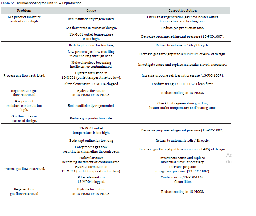
ii. Troubleshooting: Operator response to operational upsets is defined below for likely significant events. Faults of low consequence like failure of a refrigerant make up function are of low criticality and are not discussed. Operations in response to the failure of individual valves are also not discussed. The objective of the operator response will be to either attempt to maintain unit production where appropriate by sufficiently rapid intervention or if a plant trip is inevitable, to bring the plant to a safe condition ready for restart if appropriate. Troubleshooting in the refrigeration unit are shown in (Table 5)
Power generation / diesel fuel system
Troubleshooting and UCE of Unit 51 – Power Generation / Diesel Fuel System are:
i. Loss of electrical power: Load Shedding. If during the Turbo-generators operation one of them were disconnected by a trip protection or any other cause and the generation capacity of the remaining generators is not able to reachthe power demanded by the loads connected to the Plant Electrical System the Plant Management System (PMS) will indicate this through commutated contacts, voltage free, wired to terminals, to disconnect those loads of the plant defined as “dispensable”. HOLD “Loads Shedding” System awaiting document from vendor Safety Control System.
ii. Loss of instrument air: Instrument air to the power generator system will be lost through either air compressor failure or blockage of the header. The Instrument air receiver holds 15 minutes’ worth of air supply after which the whole distribution will depressurizes. In the event of total loss of instrument air to the power generators the header will begin to depressurize and the valves will fail to their fail / safe position resulting in a trip of the turbo-generators that are in commission at that timeiii. Loss of feed: Total loss of feed gas will result in a loss of all fuel gas from Unit 01 Feed Gas Metering to Unit 55. If the loss of feed gas is due to a Feed Gas Compressor trip, then ‘back up’ fuel gas will still be available from Unit 01 Feed Gas Metering to maintain a supply of fuel gas to Unit 51.
iii. Loss of feed: Total loss of feed gas will result in a loss of all fuel gas from Unit 01 Feed Gas Metering to Unit 55. If the loss of feed gas is due to a Feed Gas Compressor trip, then ‘back up’ fuel gas will still be available from Unit 01 Feed Gas Metering to maintain a supply of fuel gas to Unit 51.
iv. Emergency Shutdown is divided into:
a. Manual emergency trip switches. There are two manual hard-wired trip switches in this unit
b. Emergency generator start. On initiation of either of the following will result in ‘an open circuit breaker from 51- EL24’ signal being transmitted to 51-XS-1023 to start the Emergency Generators.
c. Turbine emergency trip protection. Emergency shutdown is initiated by pressing the EMERGENCY STOP push-button. An emergency shutdown can also be mechanically initiated by closing the manual emergency trip valve on the gauge cabinet assembly, or the manual trip button on the over-speed trip mechanism mounted on the side of the accessory gear. The main emergency trip protection for the turbine is: over-speed, exhaust temperature high, vibration high, fire extinguishing activated, loss of flame, trip oil pressure low, bearing oil pressure low, bearing supply oil temperature high, and manual emergency trip

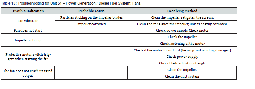
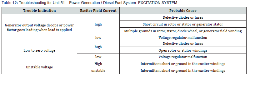
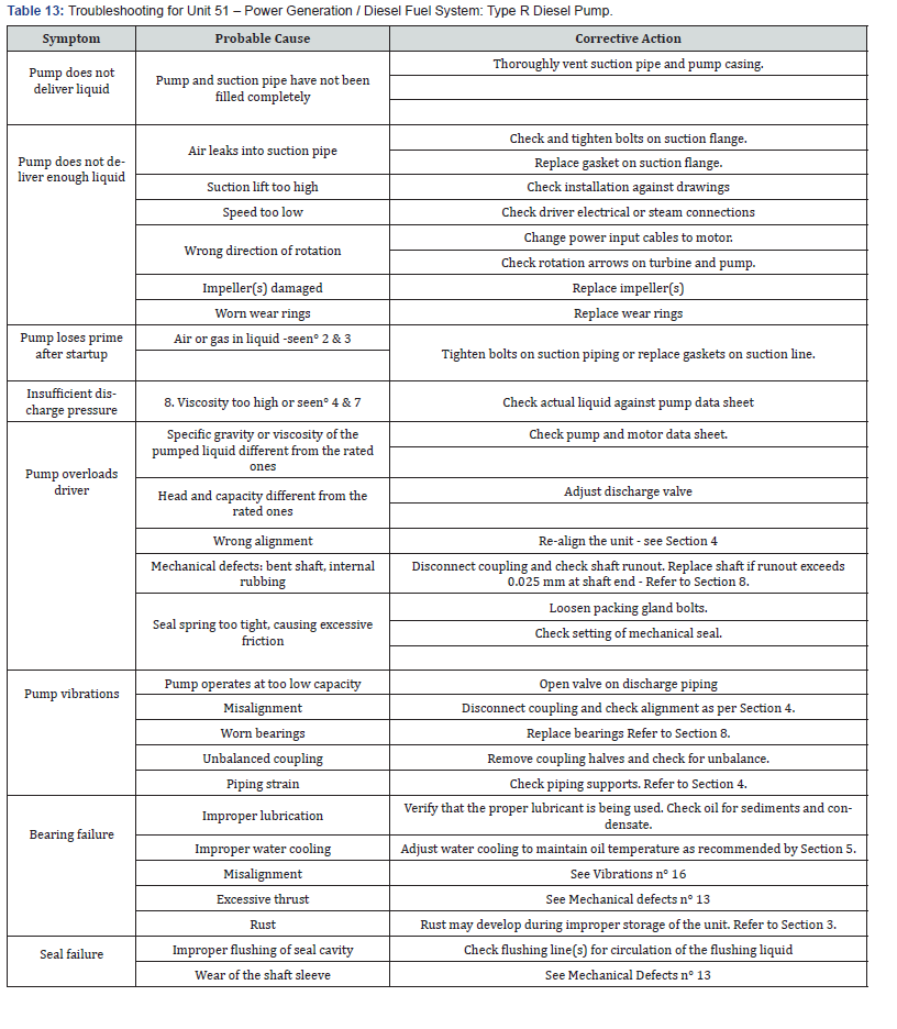
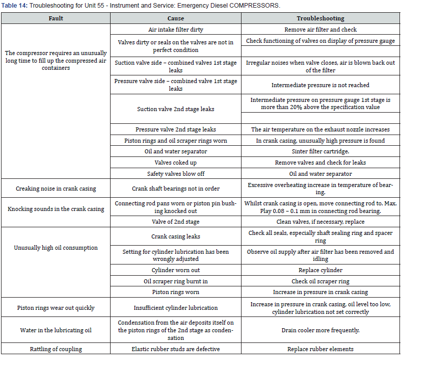
IV. Troubleshooting: They include turbo generator (stator and supervisory equipment) the troubleshooting in power generation including’s turbogenerator (fault tracing),turbogenerator (bearings), fans, bearings, excitation system, type r diesel pump, emergency diesel compressors are represented respectively in Tables 6 through A.12
Fuel Gas System
UCE and troubleshooting of unit 55- Fuel Gas System are:
i. Loss of Electrical Power. Unit 55 valves will fail close at inlet to safeguard equipment: 55-MD01, 51-MJ01-A/E, 58- MB01, and 15-MD01. Other users, leading to flare will use up the remaining fuel gas. Nitrogen is introduced manually to prevent air being present through a drop-in pressure.
ii. Loss of Instrument Air. As previous unit
iii. Loss of Feed Gas. As previous unit
iv. Troubleshooting. No Heat to Fuel Gas is observed because of fault with Start-up Fuel Gas Heater 55-ML01 and the corrective action is to check vendor manual for unit 55
Instrument and service air
UCE and troubleshooting of unit 55 - Instrument and Service Air are:
i. Loss of electrical power. In the event of loss of electrical power, the air compressor within the system will fail and hence air supply will cease.
ii. Loss of instrument air. Instrument air will be lost through either compressor failure or blockage of some kind. The Instrument air receiver holds 15 minutes’ worth of air supply after which the air distribution will depressurizes. In the event of total loss of instrument air, the following valves will fail to safeguard the system: 56-ESDV-1028. Fail Closed, 56-ESDV-1043 Fail Closed, and 56-LV-1011 Fail Open.Pressure, Level and temperature measurement is electronic or mechanical and therefore loss of instrument air should not affect their operation.
iii. Loss of feed gas. Loss of feed gas will have no effect on this system.
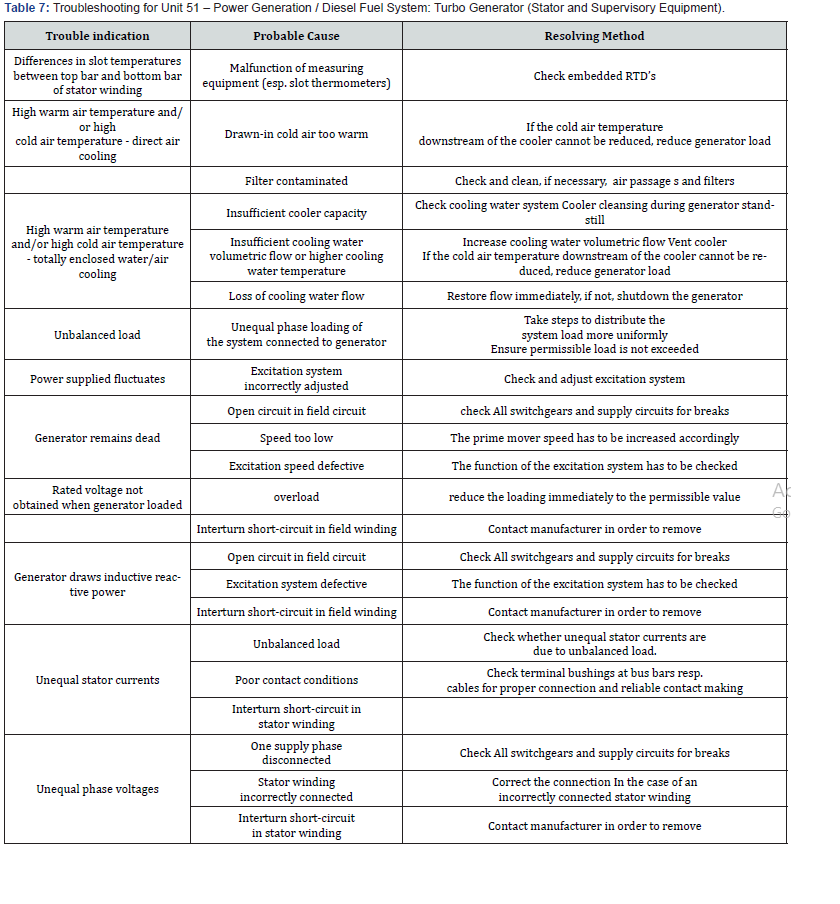
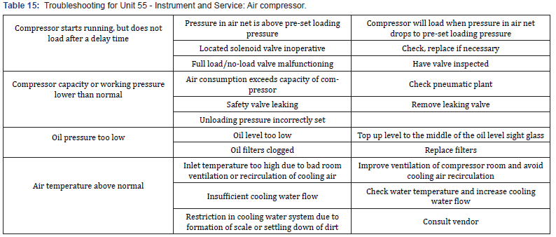
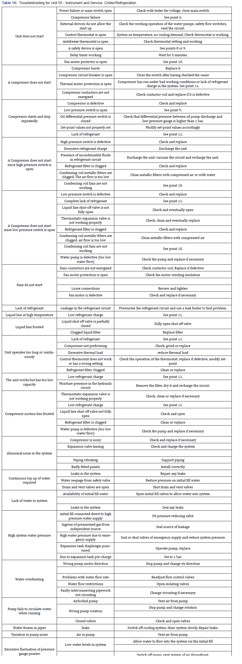
iv. Troubleshooting. Air compressor. Before carryingout any maintenance or repair, stop the compressor. When the compressor has stopped press the emergency stop button. Switch off voltage. Safeguard against unintentional ‘switch-on’. The troubleshooting in instrument and service air including’s air compressor, Chiller/Refrigeration are represented respectively in (Tables 7 & 8).

Fire protection system
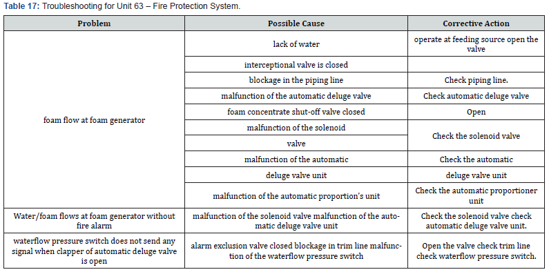
UCE and troubleshooting of unit 63 – Fire Protection System include:.
i. Loss of electrical power. Both the fresh water and the seawater fire pumps have standby diesel pumps therefore no loss in capacity is envisaged
ii. Loss of instrument air. The only instruments which will be affected by loss of instrument air are the bubbler tube level transmitters 63-LT-1000 on Firewater Storage tank 63- MF01.
iii. Loss of feed gas. Loss of feed gas will have no direct effect on Unit 63.
In the Exxon Mobil documentation, American solutions were cited 100 times, and in Russian Rosneft documentation, Russian solutions were quoted 142 times. However, in the case of the third company-British BP-the most frequently referred were not the native but the American solutions. Citations of American patents definitely dominated the total number of citations (569 citations). References to American technical thought constituted nearly 40% of all citations. Analiza dyfuzji II stopnia wykazała natomiast znaczne zróżnicowanie. However, analysis of the second degree diffusion showed significant variation. Exxon Mobil patents were most frequently cited in the CN patents (39 citation), Rosneft in RU patents (8 citations), and BP in US patents (20 citations).
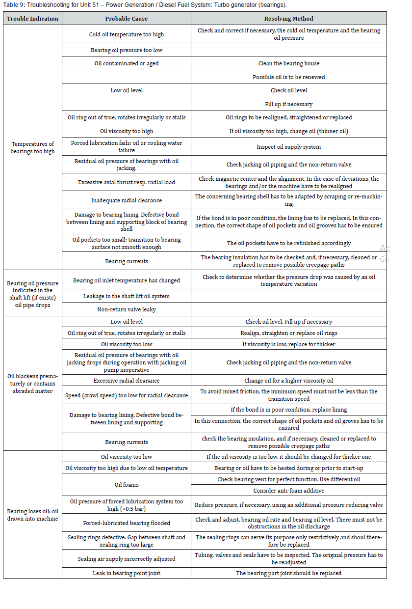
iv. Troubleshooting. In this chapter, procedures to cover problems that may occur during normal operations are given. Although this recommendation covers most problems that may be experienced, some situations that might occur which are not covered in this instruction are represented in (Table 9).
Effluent and wastewater treatment
iUCE and troubleshooting of unit 64 – Effluent and wastewater treatment include:
i. Loss of electric power. In the event of loss of electric power all motors will stop. As the pumps and air blowersare in intermittent operation loss of power will not have an immediate effect
ii. Loss of instrument air. The only instruments that will be affected by loss of instrument air are the bubbler tube level transmitters 64-LT-1007 and 64-LT-1012 on the Discharge Holding Basin 64-CV02. This will result in an apparent low low level in the holding basin, a trip of the running Effluent Discharge Pump 64-MJ04/MJ04-A, an apparent low low level in the oil separation section and trip of the Contaminated Water Recycle Pump 64-MJ02 if it is running.
iii. Troubleshooting. Unit 64 Troubleshooting are shown (Table 2. 3.10.)
Flare system
Loss of utilities and troubleshooting of unit 65 – Flare System are:
i. Loss of electrical power. In the event of loss of electrical power, the emergency diesel generators supply power to the essential services.
ii. Loss of instrument air. The unit will fail-safe and the process units will shut down on an ESD and or BD and ESD valves will fail-safe.
iii. Loss of feed gas. Loss of feed gas will have no direct effect on this system. Should the feed Gas be shut down and the LNG train shut down the whole system/equipment will be isolated depressurized and inverted to stop the ingress of air into the flare header
LNG storage and loading
Loss of utilities and troubleshooting of unit 71 – LNG Storage and Loading are:
i. Loss of electrical power. 5 turbo generators are provided for the LNG Plant. With 5 units working in parallel operation (5 units at 80%) and one trip (Status 1) – the other 4 units at 100% will pick up the full load so there is no change to the Liquefaction Unit operation. If 4 units are partially loaded and one trips but with the plant at turndown throughput, load shedding will not be required. Any other scenario may result in the power consumption exceeding that available. This will require “load shedding” of non-critical loads. Unit 71 falls into this category. The Items on Unit 71 are directly affected by loss of electrical power as follows:
a) Loss of LNG loading pumps 71-MJ01A/B/C will result in shutdown of loading operation.
b) Loss of power to the boil off gas compressor 15-MJ05A/ B/C will result in shutdown of rundown and loading operation, and therefore shutdown of the LNG train.
ii. Loss of instrument air. The plant will continue to operate satisfactorily until air header and accumulator pressures fall. The operator must make a judgement as to the best course of action should the instrument air failure persist for a prolonged period. Loss of instrument air will cause control valves to fail to their safe position, unless protected by air accumulators. This will rapidly cause interruption of both the main gas processing flow and the major liquid flows on the unit. This will lead to the closedown of rundown and loading operations.
iii. Loss of feed gas. The direct consequence of loss of feed gas is that LNG rundown to storage will cease.
iv. Troubleshooting. No observed other than that existed in vendor manuals 3.16.
Condensate storage system
Loss of utilities and troubleshooting of unit 71 – LNG Storage and Loading are:
i. Loss of electrical power. In the event of loss of electrical power then the Emergency Shutdown Valves will fail closed and the Condensate Storage Bullet 76-MD01 will be isolated.
ii. Loss of instrument air. In the event of loss of instrument air then the Emergency Shutdown Valves will fail closed and the Condensate Storage Bullet 76-MD01 will be isolated.
iii. Loss of fuel gas. A loss of condensate may mean a low level in the Condensate Storage Bullet, 76-MD01, if it is being transferred to tanker. A low-level alarm will be activated by 76-LI-1008 and if no action is taken, at a low level the unit will trip, the Emergency Shutdown Valves will fail closed and the Condensate Storage Bullet 76-MD01 will be isolated. A loss of High-Pressure Fuel Gas would mean a loss of fuel to the power generators and a plant shutdown.
iv. Troubleshooting observed are shown in (Tables 11- 17).

Recommendation and Good Operating Practice
Finally, it is recommended to check certain guidelines in order to achieve a good operating practice. Operation Consideration: Operate the compressor in accordance with this Instruction Manual & the Instruction Manual for Motor, Gear & Cooler. Especially the following items shall be observed and recorded every day on a graph, to use then data to discover any abnormality:
a) Performance for compressor: rotating Speed, process gas flow rate, suction and discharge pressure, suction and discharge temperature.
b) Shaft vibration and axial displacement for compressor, Fluid Coupling and Motor: Some of the most common causes of vibration are as follows: Improper alignment, improper coupling installation, coupling unbalance and/orlock, damage or unbalance to compressor rotor, damage or unbalance to motor rotor, failing bearings, moved machine by means of thermal growth, high thrust load, improper lube oil pressure and/or temperature, compressor surging phenomena, worsen oil property.
c) Bearing & temperature for compressor, Gear and Motor: When a difference in the oil temperature between the oil at the oil cooler outlet and at the bearing is 5°C higher than that of the normal operation without any change of other operating condition, pay sufficient attention to and observe the temperature change.
d) Operating data for motor: shaft vibration, purge air temperature, winding temperature, bearing temperature.
e) Operating data for lube oil & buffer gas system: delivery pressure of oil pump, inlet and outlet temperature of oilcooler, differential pressure of lube oil filter, oil level in oil reservoir, differential pressure of buffer gas filter, differential pressure of buffer gas supply, dry gas seal leakage pressure.
f) Observation of Lube Oil for Oil Unit: observe the color and the foaming of the oil and analyze the oil in the oil reservoir.
g) Compressor surging: Be sure the compressor is not operating in a condition of surge. Severe surging can be recognized by a heavy thumping noise in the compressor, an accompanied by excessive vibrations, a Fluctuating pressure and the process temperature increases.
h) Flow rate of lubricant: Lubricant oil shall be periodically checked for the static electricity, kinetic viscosity, water content, sulfur content, color, etc.
i) Pump checks: the spare pump should be set to auto ready to cut in if a failure occurs on the running pump, the flow of lube oil through the sight glass and the leaks on mechanical seals and bearings, the lineup of the filters must be controlled. The temperature and the vibration of the bearings/ shaft. Report any abnormal noise or smell.
j) Electrical motor checks: The load current (amps consumption), the level in the oil reservoir, the vibrationsof the bearing must be checked. The connection of electrical earth cables, the air is coming out of the fan, the cooling fins are clean must be controlled. Report any abnormal noise and/or smell.
k) Oil filters checks: If the differential pressure across the filter is above normal value (depends on type), change over the filter. In this case be sure that the clean one is put in service first, once cleaned, line up the filter on stand-by.
l) Oil cooler checks: the outlet temperature of the oil, the lineup of the spare cooler and the leaks must be controlled.
References
- Saeid Mokhatab, John Y Mak, Jaleel V Valappil, David A Wood (2014) Handbook of Liquefied Natural Gas. In: (1st edn), Gulf Professional Publishing, Elsevier, USA.
- Saeid Mokhatab, William A Poe, John Y Mak (2015) Handbook of Natural Gas Transmission and Processing Principles and Practices. (3rd edn.), Gulf Professional Publishing, Elsevier, USA.
- John L Woodward, Robin Pitblado (2010) LNG Risk Based Safety: Modeling and Consequence Analysis. Aiche, John Wiley & Sons, Inc., Canada and USA.
- Michael D Tusiani, Shearer Gordon (2007) LNG: A Nontechnical Guide, PennWell, USA.


