Perspective of Use of Rubber Linings in Drum Ball Mills
Chizhik EF* and Gerasimenko II
Limited Liability Company, Research and Production Enterprise Mekhanobr- Polymet, Ukraine
Submitted: January 13, 2023; Published: March 10, 2023
*Corresponding author: Chizhik EF, Limited Liability Company, Research and Production Enterprise Mekhanobr- Polymet, Dnipro, Ukraine
How to cite this article: Chizhik EF and Gerasimenko II. Perspective of Use of Rubber Linings in Drum Ball Mills. JOJ Material Sci. 2023; 7(4): 555718. DOI:10.19080/JOJMS.2023.07.555718
Abstract
When developing the designs of rubber linings for drum mills, the authors were guided by the principle of the main priority - creating conditions for improving the technological performance of grinding, along with increasing the service life, using the unique property of rubber - elasticity. Theoretical studies, the results of laboratory tests, confirming the rationale for the design and acceptable operating conditions, as well as the technological indicators obtained as a result of industrial tests for each created design, are presented.
Keywords: Rubber lining; Rubber elasticity; Ore grinding mill; Dynamics of medium movement; Intensification of grinding; Shock loads; Technological indicators
Introduction
Ore preparation processes - crushing, grinding, classification, the largest number of conflicting theoretical, design and technological solutions have been created regarding grinding (separation) in drum mills. These contradictions became much more acute in the 60s of the 19th century with the beginning of the use of special rubbers as a structural material for linings.
We take the liberty of asserting that the generally accepted well-established modes of movement of the intra-mill load (cascade, waterfall, mixed) do not exist in time due to the laws of physics of the movement of loose media (a mixture of balls with ore is one of the forms of a loose medium). Also, when the mill rotates, an angle of repose (the angle of spontaneous collapse) will necessarily be created. The unique property of rubber - elasticity (elasticity) will change the dynamics of the movement of the intra-mill environment, and a certain design of rubber drum linings will contribute to the creation of a vibration effect. The trend of the obligatory presence in the design of the lining of the lifter (protruding beam) when using rubber becomes an extremely harmful element for ensuring the grinding process.
Substantiation of Scientific and Design Developments
It is necessary to carry out theoretical and design developments to create a rational working profile of the rubber lining and manufacturing technology. Manufacturers of drum mills are required to set a speed that ensures that the medium rises to an angle of 75-80 degrees from the critical one. Therefore, the presence of a lifter not only increases the angle of elevation, but also creates an initial acceleration of the medium, which worsens the technological performance. The use of rubber lifters will lead to intense wear and additional repairs to replace them. In general, the rubber lining will be subjected to static and dynamic loading with alternating deformation (compression, tension) during the rotation of the mill. At the same time, there will be a direct impact of the balls on the surface of the lining, causing compressive and tensile deformation due to the formation of a recess (hole).
Results of Theoretical Studies and Industrial Tests
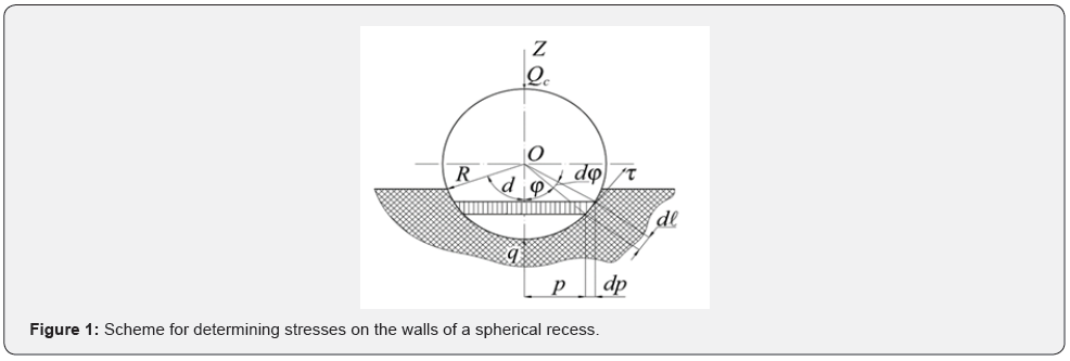
To study the magnitude of stresses along the section of the recess Let us consider the forces that arise when a ball is embedded in rubber (Figure 1).
At each point A of the ball surface, the specific normal pressure and tangential friction forces occur due to the sliding of the rubber surface layer displaced from the recess relative to the ball. Let us consider an annular element of the surface of a sphere with an area.

Assuming a change in the specific pressure along the depth of the spherical recess according to the cosine law, we obtain.

where q0 is the specific pressure at the point ϕ = 0 .
Let’s find the projection of the specific normal  and tangential
  forces acting at point A on the vertical axis:

Here, the specific forces of friction τ and normal pressure  are related by the relation.

where f is the coefficient of friction when the ball slides over the rubber.
The force pressing the ball into the rubber, taking into account expressions (1) and (3), will have the following form:

Substituting expressions (2) and (4) into formula (5), we obtain

Hence the maximum specific pressure in the spherical recess

From expression (7) it can be seen that with an increase in the angle α , which corresponds to an increase in the hardness of rubber, the specific pressures in the center of the recess increase and at α → 0 , q0 → ∞ . From expressions (2) and (7), the formula for the specific pressure at any point of the spherical recess can be obtained in the form

Using relations (7) and (8), it is possible to calculate the specific pressures on the walls of a spherical recess (Table 1).

It can be assumed that as the impact load increases, the rubber begins to break down in the cavity, followed by a transition to the periphery. An analysis of expressions (7) and (8) shows that the specific pressures in the recess under the same static or impact load are inversely proportional to the diameters of the balls. These expressions can be used as one of the factors in choosing the diameters of steel balls in order to reduce the maximum specific pressures (stresses) on the rubber lining of the mill. Starting in 1965 to create a rubber lining design, the above arguments and the factor of impact energy transfer propagated in the lining array in the form of a wave of elastic vibrations were taken into account.
We believe that the main purpose of linings on the cylindrical part of the mill drum is to create a mode of movement of the intra-mill environment, which ensures the highest technological and operational performance. Figure 2 shows photographs of the design of the rubber lining developed by us for carrying out technological tests at mills МШЦ 3600х5500. For comparison of indicators, 4 (four) mills were installed, two with a rubber lining and two with a metal one. Accordingly, loaded with balls with a diameter of 40mm and cylpebs. The test results are presented in table 2.


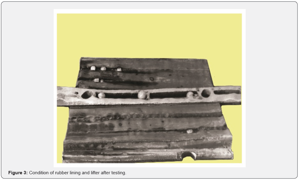
As can be seen from table 2, no significant technological advantages were obtained on the rubber lining “plate-lifter” in comparison with metal ones. Structurally, the rubber lining plates are made with grooves along its length to jam the balls, which reduces the area of direct contact of the balls with the surface of the plates, and also uses the elastic properties of rubber to hold them. This technical solution makes it possible to reduce the stresses in the rubber mass, which increases the service life and intensifies the grinding process due to the creation of a metal substrate and the occurrence of recurrent elastic deformation. The metal lifter is also made with grooves for jamming the balls. In general, such a constructive solution significantly reduces the consumption of materials, improves the technology of casting and heat treatment. The wear intensity is higher than that of a rubber plate, but a single service life is ensured - 24 months of operation (Figure 3).
Possessing greater kinetic energy, the rate of penetration into the rubber surface (the formation of depressions) from balls with a diameter of 100 and 80mm will cause instantaneous compression along the axis of the ball. Tension predominates on a spherical surface. The time taken for instantaneous compressive deformation is less than the time required for stretching. This leads not only to the formation of microcracks in the zone of instantaneous compression, but also to the occurrence of pyrolysis phenomena in the lining array, due to the wave transfer of impact energy. To increase the contact area and the time for compression, it is necessary to use the elastic properties of rubber, i.e., to create structural deformation. Mooring fenders are a convincing example of the combination of rubber and air. Based on this, it is most rational to create a rubber lining with an air cavity.
In order to compare the strength characteristics of solid rubber plates and those with an air cavity, laboratory tests of the manufactured models with a size of 280 × 200 × 80mm were carried out. With the same external dimensions, the size of the air cavity in the shell lining model corresponds to 240 × 120 ×24 mm with a rubber layer thickness above the cavity of 36 mm. The absolute air pressure in the cavity was taken to be 0.1 MPa. On a special impact driver that provides a single impact, the plate models were hit by a ball 100 mm in diameter, covered with a coloring agent and falling from a height of 1 m. The diameter of the contact patch of the ball on the surface was fixed, taking into account which the penetration depth of the ball was calculated by the formula:

where D is the ball diameter.
K is the ratio of the contact spot diameter to the ball diameter.
The maximum impact force of the ball (index 1) on a smooth surface (index 2) is determined by the formula:

the depth of penetration of the ball into the plane is calculated:

impact duration (from the moment of the first touch to the moment of the greatest compression):

where E1 and E2 are the moduli of elasticity of the colliding bodies.
R is the radius of the ball.
ρ1 is the density of the ball material.
V1 - the speed of the ball when it meets the plane.
ν1 and ν2 are Poisson’s ratios for the material of the sphere and plane, respectively.
Taking into account the experimentally found depth of penetration of the ball into the plane [1]. we determine from formula (13) the coefficients of elasticity of the shell plate and solid rubber:

and using the characteristics calculated by formulas (10) and (11), we determine the impact force and impact time.
The results of experiments and calculations are shown in table 3 & figure 4.
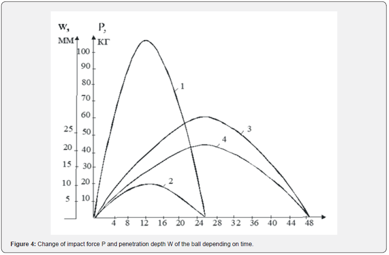

a) impact force for a rubber plate.
b) depth of penetration of the ball for a rubber plate.
c) impact force for shell lining.
d) penetration depth of the ball for shell lining.
As can be seen, under equal loading conditions (a ball with a diameter of 100mm, a fall height of 1m), the impact time of a ball with a shell plate is twice as long as the time of collision with a solid rubber one, which reduces by half the maximum impact force and the corresponding specific load perceived by the shell plate.
The ability of rubber shell plates to absorb shock loads twice as much compared to rubber linings of conventional designs gives grounds for their use in mills operated with balls with a diameter of 100mm. Laboratory tests have confirmed the promise of creating rubber linings with an air cavity. First of all, it is necessary to determine and justify the profile of the lining (section of the working surface). In 1969-1970, of the many existing profiles of metal linings, the service life and technological performance with a wave working surface (wave profile) was the most ensured.
Creating a rubber lining with an air cavity, for the first time the working surface was made in the form of an equilateral trapezoid. On the working surface, spherical recesses were placed for jamming balls with a diameter of 40 to 100mm. Assuming that the proposed wave design, along with the elastic properties of rubber, will create conditions for the interaction of the intra-mill load during the rotation of the mill, similar to the processes that occur in the mudflow head. By the beginning of the design of such a lining, there was no information on the fatigue limit in rubber under alternating deformation. As for metals, it is well known that samples are destroyed within 100 thousand cycles. Rubber technologists, specialists in the manufacture of tank tracks, verbally assured that rubber exceeds the fatigue limit of metals by at least 2–3 orders of magnitude more.
Not having sufficient experience in filling molds with internal barriers, using injection molding technology, it was decided to limit the length of the lining to 500mm. Novokramatorsky Mashinostroitelny Zavod produced molds (shapers) and a special drum for the MShTs 3600 x 4000 mill, with holes drilled along its length in 500mm increments for attaching the rubber lining with a special pin. Tests carried out in 1972 with balls with a diameter of 100mm showed the promise of the lining of this design and revealed that rubber also has a fatigue limit under alternating loads.
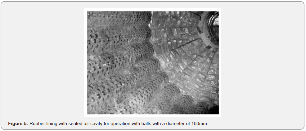
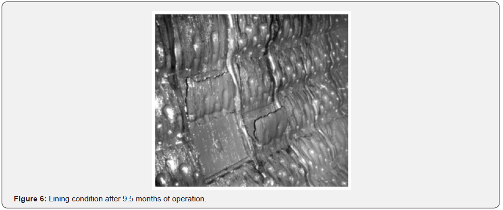
This figure 5 shows the image of a new wave lining with an air cavity and spheres on the working surface for ball jamming. With a service life of metal linings of 7 months, the wave rubber lining at the next inspection of the mill after 9 (nine) months of operation had wear on the working surface within 35-40 mm. However, after 20 subsequent days of operation, the destruction of the peripheral bridges forming the internal air cavity began on separate linings, and the working surface was torn off (Figure 6). From the dynamic impact of the intra-mill load with balls with a diameter of 100 mm during the rotation of the mill, the bridges were subjected to simultaneous compression in the lower part of the drum, tension in the upper and shear deformation when located on the sides.
Based on the number of revolutions of the mill and the service life of 290 days, it is easy to calculate the number of alternating deformations - 7.5 million cycles. This is 75 times higher than the fatigue of metals.
Since the initial feed at the experimental mill with a rubber lining and the control one with a metal one was maintained equal, we can state:
a) at the mill with a wave rubber lining, the specific consumption of balls and electricity decreased by 8-10 percent.
b) however, the content of the finished class - 0.074mm in the discharge of the mill (unloading) is higher than the control by 15-18 percent.
It should also be noted that after 3 (three) months of operation, on some linings in spherical recesses, there were no balls with a diameter of 100 mm within 1-2, i.e., single ones. Wear of the working surface in different parts of the mill did not exceed 10 mm. After 5 (five) months of operation, the total wear amounted to 23-27mm, which exceeds the wear rate by two times compared to three months of operation. Also, the number of missing balls in spheres for balls with a diameter of 100 mm increased (about 20%) and separate spheres for balls of 80mm.
As can be seen from the photo (Figure 6), in the absence of balls, the lining surface wore out in the form of grooves of various depths and widths. If we compare the reliability of holding the balls in the sphere and in the longitudinal grooves, a clear priority is given to the longitudinal grooves. So, to extract the balls from the longitudinal grooves on the linings, figures 2 & 3, a significant effort was required after 24 months (720 days) of operation.
According to the test results of the wave rubber lining with an air cavity in the MShTs 3600x4000 mill with balls with a diameter of 100 mm, it should be noted:
a) The prospect of filling molds with rubber using injection molding technology. High quality linings.
b) The method of fastening with a pin with vulcanized metal reinforcement is the most effective in terms of reliability and service life of the lining as a whole.
c) The advantage of the wave profile of rubber linings with oriented grooves on the working surface.
d) Balls wedged in the grooves help to reduce internal stresses in the lining array, and also intensify the grinding process.
e) It is not advisable to have a lifter in the design of the rubber lining.
f) Absence of hydroabrasive wear of the drums due to the tight fit of the lining to the surface.
g) Exclusion of injuries.
h) Sphere for jamming balls is not suitable. The grooves are more efficient. Limit the size of balls for jamming.
In order to successfully use air cavity rubber liners, more research is needed on the choice of cavity parameters, the quantitative use and spacing across the width or height of the slab, the optimization of air pressure, and the number and geometry of the bridges creating the cavity.
However, in order to expand the scope of rubber linings, we consider it rational to carry out research and development work to create a non-lifter structure with a wave profile. Here, optimizes the location of the grooves (recesses) for jamming the balls, taking into account the movement of the intra-mill environment.
When the ball collides with the speed v 0 with the surface of the lining, the dynamic force action is described by the dependence:

where k and n are empirical coefficients characterizing the deformation.
Then the basic impact equation can be represented as

where ν is the speed of approach of the centers of inertia of the bodies. M is the reduced mass of colliding bodies,

m1 and m2 - the mass of the ball and the lining plate, respectively.
Since the lining plate is rigidly fixed to the surface, it can be considered as a body with an infinitely large mass, therefore,

and the reduced mass of the colliding bodies will be equal to the mass of the falling ball. Integrating expression (17), we obtain the displacement of a ball with mass m1, which at the moment of contact with the lining plate has a speed v0

It should be noted that during impact, the rubber is loaded in a dynamic mode, and when performing calculations, it is legitimate to use the dynamic rubber modulus corresponding to the loading speed. Thus, the expression for moving the center of gravity of the ball will be written as follows:

Equation (19) is solved by numerical integration.
For integration, we divide the impact period into q intervals with the value τ.
We assume that in each time interval (q −1)τ < t < qτ the force P(t1) changes according to the linear law

The thickness of the rubber lining is calculated taking into account the allowable relative deformation [ε] of rubber plates, which is determined by laboratory tests [1]. under shock loading and should not exceed 0.25 ... 0.30 (the ratio of the depth of penetration of the ball to the thickness of the rubber plate):

where ε is the deformation of rubber plates.
The physical and mechanical characteristics of the colliding bodies for the falling balls corresponded to the characteristics of steel, and for the lining plates - to the characteristics of wear-resistant carbon black-filled rubbers. The performed calculations for the most unfavorable case of loading with a deformation of rubber plates of 30mm with a thickness of 130- 160mm are able to withstand temporarily overestimated loads without damage.
The design development of the lining was carried out with a thickness of 160mm, on the sides of the working surface, grooves of the opposite direction are provided at an angle to the longitudinal axis of the plate.
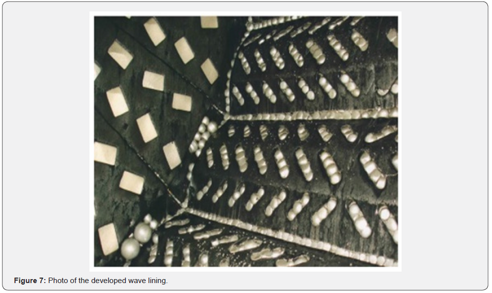
On figure 7 shows a photo of the developed wave rubber lining, which shows that there are wedged balls in the grooves.
The results of technological indicators are shown in table 4. Comparing the technological performance of mills with a rubber lining “plate-lifter”, shown in table 2 and obtained on the wave lining, table 4 clearly shows the priority of the developed design of the wave lining. According to the results of the operation of wave linings in mills with a diameter of 2.1m to 5.5m under sharply different conditions in terms of ore size and ball diameter, it should be stated:

(*) The actual service life of the lining on the drum - 38 months, end - 30 months.
a) Intensification of the grinding process on wave linings with a working surface saturated with balls, due to a change in the dynamics of the movement of the medium, similar in its effect to the processes occurring in the mudflow head.
b) The destruction (grinding) of larger pieces of ore is provided by balls of smaller diameter and in a shorter section along the length of the mill.
c) The wear intensity of wave rubber linings in the half of the mill from the loading cover is 1.5–2 times higher than in the second part of the mill near the discharge cover.
Thus, the tests carried out in 1999 at IPO Erdenet at the MSHTS 5500x6500 mill with 100mm balls with rubber lining “wave” (ore size -35mm) confirmed that the entire grinding process takes place at a distance of 2.0-2.5m from loading lid. The intensity of wear of the lining along the length of the mill decreases towards the discharge cover and differs in value by 6 times. Such a phenomenon with a similar difference is not observed with metal linings, regardless of the size of the balls from 40mm to 120mm. This result was obtained for the first time in mills of the first grinding stage. It has also been established that from the first hours of operation, the specified performance for the initial power supply is provided.
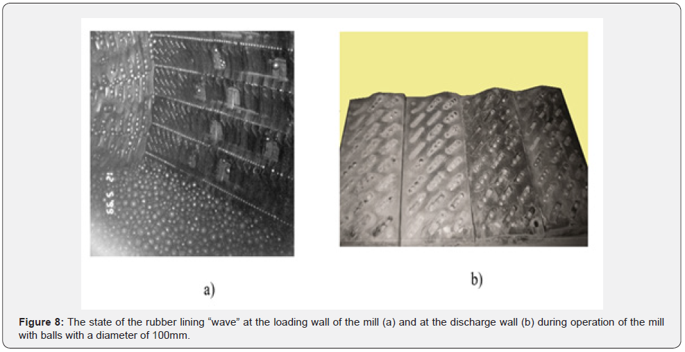
Similar phenomena are observed at all mills MShTs 4000x6000 with a rubber lining wave, operated by the mines of Petropavlovsk Management Company (Figure 8). With the actual size of the ore in the feed -20mm, balls with a diameter of 60mm provide complete grinding at a length of 2.0-2.5 meters from the loading lid. The linings of the second half of the mill can be in operation for at least another 12-16 months. However, dismantling is carried out due to complete wear, before the embedded reinforcement in the first half of the mill in 30-38 months (at different mines).
This phenomenon of decrease in wear intensity is explained by self-protection in the presence of a layer of finely ground ore particles. This layer effectively performs the function of an energy absorber, including shock pulses transmitted to the surface of the lining. The property of being a strong absorber of wave energy is common to all porous materials (a mixture of fine ore with water is also an energy absorber). As a characteristic of the energy absorption capacity of the material, we use the absorption coefficient d, which shows at what distance Δx the pressure amplitude of a plane traveling wave decreases by e times.

The value α can also be interpreted as a relative decrease in amplitude per unit distance.

The linings that provide the most protective layer are those with vulcanized permanent magnets. Such linings were presented by the Swedish company Trelleborg, however, their scope was limited only to balls with a diameter of 40mm. We have fulfilled the theoretical prerequisites for the expediency of creating rubber linings with permanent magnets [2].
However, unlike Trelleborg, they used the unique property of rubber - elasticity. This allowed the lining to be made not with vulcanized permanent magnets, but with built-in, i.e., replaceable, also retain scrap not only due to the magnetic field, but also with the help of elasticity. In this case, scrap of various sizes is concentrated in certain places on the surface of the slab, creating a wave profile. In addition, the retention of the lining on the drum was strengthened by a special design solution. As a result, the lining can be operated with balls with a diameter of 80mm.
In general, on the basis of the above scientific and design developments, it is necessary to state:
a) Wave designs of rubber linings with saturation of the working surface with balls provide a significant increase in service life and create conditions for intensifying the grinding process. The arrangement of vulcanized reinforcement in the lining structure for fastening to the drum with pins increases the reliability of fastening, prevents the penetration of pulp between the lining and the drum, and additionally increases the service life of the linings and the drum as a whole.
b) According to the results of operation of mills of various diameters, an increase in productivity was confirmed, both in terms of initial feed and finished class, as well as an increased content of smaller classes (40 microns and less) in the unloading of mills.
c) A significant reduction in the specific consumption of balls and electricity has been established.
d) Theoretical studies made it possible to substantiate that grinding on wave rubber linings is ensured in a shorter section of the mill within 2-3 meters of its length. Industrial tests have confirmed that at a distance of 2–2.5 m from the loading wall, grinding is most intensive. Further to the discharge wall, the process of regrinding with a total ball load takes place.
e) When operating mills with balls with a diameter of 100mm, the service life of rubber wave linings along the length of the drum differs by 6 times - respectively, near the loading and unloading walls. In this regard, it is advisable to install wave linings of various designs to ensure a single service life.
f) A technology has been proposed for combining two grinding stages in one drum of ore grinding mills with the obligatory use of linings with permanent magnets and the installation of a dividing grid.
g) The expediency of widespread use of wave rubber linings instead of the “plate-lifter” design has been proved.
Conclusion
This article provides a chronology of the creation of rubber linings, with the obligatory use of elastic properties, to protect the surface of drum ore grinding mills, as well as changing the dynamics of the movement of the intra-mill environment, providing a significant improvement in grinding technological performance.
The goal is to involve specialists, especially mining companies, for a critical analysis of the generally established processes in the mill drum. The time has come to carry out the grinding process in two stages in one drum with the installation of a dividing grid. Therefore, in two drums it is possible to have four stages of grinding with the obligatory use of magnetic linings. The problem of removing scrap from the drum is being solved, because it becomes technologically important for increasing the service life of magnetic linings and the formation of a size class from less than 74 microns to 40 microns.
On the way of physical development and the perception of the results of technological progress, difficulties have always arisen due to a one-sided understanding of phenomena, both natural and man-made. The authors believe and hope for the expediency of a face-to-face meeting to discuss not only the aspects touched upon in the article, but also a discussion on the injection molding technology for the production of large and complex rubber products, including screening surfaces (sieves) for classification. We would like to thank in advance the experts who accepted our proposal and ensured the organization of the meeting.
References
- Chizhik EF (2021) Development of design and production technology of rubber linings for ball mills. Mining magazine 11: 39-44.
- Chizhik EF, Korotyshev EV, Khablo GP (1989) Preferred concept of linings with magnetic elements Crushing and grinding equipment and disintegration technology. Leningrad, p. 64-70.


