


New Cuts of Quartz for Surface Transverse Wave Temperature Wireless Sensors
Waldemar Soluch1 and Ernest Brzozowski2*
1ELBIT, Poland
2Lukasiewicz Research Center, Institute of Microelectronics and Photonics, Poland
Submitted: November 12, 2021; Published: December 09, 2021
*Corresponding author: Ernest Brzozowski, Lukasiewicz Research Center, Institute of Microelectronics and Photonics, Poland
How to cite this article: Waldemar S, Ernest B. New Cuts of Quartz for Surface Transverse Wave Temperature Wireless Sensors. JOJ Material Sci. 2021; 6(5): 555696. DOI:10.19080/JOJMS.2021.06.555696
Abstract
A surface transverse wave (STW) in quartz is interesting for application at high frequencies because of higher velocity than that of a surface acoustic wave (SAW). STW propagates along the plane of Y rotated cut perpendicularly to X axis of quartz and is described as θYX90o, where θ is rotation angle. The plane should be covered with periodical electrodes and period of electrodes p should be equal to λ/2, where λ is the STW wavelength. So far, the STW were investigated only for the temperature compensated cut at θ ≅ 36o. In this work we experimentally investigated three cuts with expected high first order temperature coefficients of frequency (TCF1). For θ ≅ 43o (ST cut for SAW propagating in the X direction), TCF1 ≅ 35 ppm/oC, was obtained. However, the second order coefficient TCF2 ≅ -53 ppb/oC2 introduced relatively large nonlinearity to the frequency changes against temperature. For the new cuts at θ ≅ 47o and θ ≅ 55o, the TCF1 of about 45 ppm/oC and 71 ppm/oC respectively, were obtained. TCF2 = 0 was obtained for both cuts. The results show that the STW on the new cuts of quartz are attractive for application in wireless temperature sensors.
Keywords: Nanophases; Irradiation with gamma-quanta; Decay of light nuclei; Optical absorption; Light scattering
Introduction
The Surface Transverse Wave (STW) propagates along the plane of Y rotated cut perpendicularly to X axis of quartz, which is described as θYX90o, where θ is the rotation angle. The plane should be covered with periodical electrodes and period of electrodes p should be equal to λ/2, where λs the STW wavelength [1]. So far, the STW were investigated only for the temperature compensated cut (θ ≅ 36o) [2]. For applications in the temperature sensors, new cuts, with sufficiently large linear temperature coefficients of frequency should be found. Because both Love and STW have only horizontal components of mechanical motion parallel to the X axis of quartz, it is expected that measured temperature coefficients of frequency will be similar to both waves [3]. Large velocity, lack of vertical component of mechanical motion (no air load losses compared to SAW [4]), larger penetration depth and possibility of large linear temperature coefficients of frequency, make the STW attractive for application in the temperature sensors at high frequencies.
Materials and Methods
Taking into account the calculated results for the first and second order temperature coefficients of frequency presented in [3], the following three rotated Y-cut angles θ were chosen for measurements of the STW properties: 43o, 47o and 55o. The first cut is the well known ST cut used for SAW propagating in the X axis direction. The following general expressions for such STW parameters as phase velocity ν, electromechanical coupling coefficient K2 and the reflection coefficient γ of a single aluminum electrode, can be written as [5]:
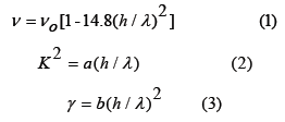
where h is the aluminum layer thickness and λ is the STW wavelength. Velocity νo and the coefficients a and b depend on the cut angle of quartz.
Photolithographic mask (Figure 1), designed for the STW resonator on the temperature compensated cut of quartz (θ = 36o) [5] was used in the present work. Here W = 1mm, p1 =5 μm, p2 = 4.9 μm, p3 =4.98 μm, λ = 2p1 =10 μm. The numbers of electrodes for the reflector, for the phase shifter, for the IDT and for the centre grating were equal to 800, 45, 121 and 225, respectively
The resonators were fabricated by the lift-off method for the aluminum layer thickness h = 0.1 μm (h/λ = 1%) and measured (Agilent Technologies Network Analyzer Type 8753ET). As an example, amplitude response of a resonator on the θ = 55o cut quartz is shown in Figure 2. Using the algorithm presented in [2], the STW parameters were changed until the measured and calculated amplitude responses were matched. The obtained parameters are shown in Table 1. These parameters can be used for design of the STW resonators.


Results
The STW resonators were located in the temperature test chamber and the relative changes of frequency against temperature were measured. The result of measurements are shown in Figure 3. A temperature dependence of frequency f(T) can be written as:
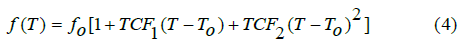
where To is the reference temperature and fo is the frequency at T = To.
The first and second order temperature coefficients of frequency defined as:
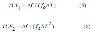
were determined from the measurements and are presented in Table 2.
It can be seen that for the 43o cut significant TCF2 exists, while for the new cuts this coefficient is equal to zero. It is expected that the property will also exist between the 47o and 55o cut angles.
To verify the above results, a resonator for the first ISM band at a frequency of about 434 MHz, was designed and fabricated on the 55o cut. Using the STW parameters determined previously (Table 1) and the design guidelines presented in [5], the following data of the resonator structure were obtained: W = 1mm, p1 = 5.37 μm, p2 = 5.31 μm, p3 =5.35 μm and λ = 2p1 = 10.74 μm. The numbers of electrodes for the reflector, for the phase shifter, for the IDT and for the centre grating were equal to 600, 177, 141 and 220, respectively. The obtained amplitude response of the resonator, for the aluminum layer h = 0.1 μm, is shown in Figure 4.


Taking into account the internal insertion loss of the measuring system of about 2 dB, the net insertion loss 6 dB and the center frequency 433.865 MHz, were obtained. The loss coefficient Ti ≅ 0.754 was used to match the calculated and measured net insertion loss and loaded QL and unloaded QU quality factors of about 3400 and 7000 respectively, were obtained to verify the above results, a resonator for the first ISM band at the frequency of about 434 MHz, was designed and fabricated on the 55o cut. Using the STW parameters determined previously (Table 1) and the design guidelines presented in [5], the following data of the resonator structure were obtained: W = 1mm, p1 = 5.37 μm, p2 = 5.31 μm, p3 =5.35 μm and λ = 2p1 = 10.74 μm. The numbers of electrodes for the reflector, for the phase shifter, for the IDT and for the centre grating were equal to 600, 177, 141 and 220, respectively. The obtained amplitude response of the resonator, for the aluminum layer h = 0.1 μm, is shown in Figure 4.


Taking into account the internal insertion loss of the measuring system of about 2 dB, the net insertion loss 6 dB and the center frequency 433.865 MHz, were obtained. The loss coefficient Ti ≅ 0.754 was used to match the calculated and measured net insertion loss and loaded QL ≅ 3400 and unloaded QU ≅ 7000 quality factors.
Discussion
Both structure and design of the STW asynchronous resonator is complicated because of different period of electrodes in the IDTs, in the center grating, and in the phase shifters [5]. For lower quality factors, simpler STW components can be used. For example, amplitude response of a STW delay line composed of 3 IDTs, was first presented in [3]. Internal reflections inside the IDTs and reflections between them changed the shape of the amplitude response and low insertion loss was obtained. Another possibility is a STW filter [6]. The filter consists of two long IDTs and a short grating shield located between them. Period of electrodes is equal to λ/2 and is constant along the whole length of both components. So far, one-port STW resonator was not investigated.
STW can also be used in the wireless passive sensors [7]. In this case, the distances between reflectors should be covered by metal gratings with period of electrodes smaller than λ/2 [5].
Conclusion
Such STW parameters as velocity, electromechanical coupling coefficient, reflection coefficient of a single aluminum electrode and temperature coefficients of frequency were determined experimentally for the 43o, 47o and 55o cut angles of Y rotated quartz. High velocity, high sensitivity and good linearity of the relative frequency changes against temperature was obtained for the last two cuts. The obtained results show that the STWs on the new cuts of quartz are attractive for application in wireless temperature sensors at high frequencies.
References
- Thompson DF, Auld BA (1986) Surface transverse wave propagation under metal strips grating. IEEE Ultrason Symp Proc, pp. 261-266.
- Auld BA, Thompson DF (1987) Temperature compensation of surface transverse wave for stable oscillator applications. IEEE Ultrason Symp Proc, pp. 305-312.
- Nishikawa T, Tani A, Shirai K, Takeuchi C (1980) SH-type surface acoustic waves on rotated Y-cut quartz. Frequency Control Symposium, pp. 286-291.
- AJ Slobodnik (1976) Surface acoustic waves and SAW material. Proc IEEE 64(5): 581-595.
- Soluch W (2007) Design and properties of STW asynchronous resonators on quartz. IEEE Trans. Ultrasonics, Ferroelectrics, and Frequency Control 54(2): 413-417.
- W Soluch (2003) STW filter with long interdigital transducers on quartz. Electronics Letters 39(17): 1292-1293.
- Reindl LM (2008) Wireless passive sensors: basic principles and performances. Proc. IEEE Sensors Conference, pp. 1607-1610.


