


Finite Element Modeling of HDPE Utility Poles with Fiberglass Rebars
Sriram Kalaga1* and Vaishnavi Kalyanaraman2
1 Consulting Structural Engineer, USA
2Aeronautical Engineering Department, MVJ College of Engineering, Bengaluru, India
Submission: December 04, 2019; Published: December 11, 2019
*Corresponding author:Sriram Kalaga, Ph.D, P.E, F.ASCE, Consulting Structural Engineer, 602 North Shore Drive, Glen Burnie, Maryland 21060 USA
How to cite this article:Sriram K, Vaishnavi K. Finite Element Modeling of HDPE Utility Poles with Fiberglass Rebars. Eng Technol Open Acc. 2019; 3(3): 555612. DOI: 10.19080/ETOAJ.2019.03.555612
Abstract
A finite element (FE) model is developed to analyze the behavior of HDPE poles integrally reinforced with fiberglass rebars. The 4-element model is analyzed to determine elastic lateral deflections under specified tip loads. Pole cross section properties were derived for sections with 12 and 16 rebars. The model is validated by comparing results with those from full-scale tests. It is observed that the FE values agree very well with tests. Pole load class rating is evaluated based on serviceability considerations. Further extension of the concepts is discussed.
Keywords: Deflections; Fiberglass; HDPE; Finite element; Matrix; Poles; Rebar; Serviceability
Introduction
Poles of various materials are used as support structures in power transmission and distribution lines. Typical heights of these utility poles are 7.6m to 18.6m (25ft. to 61ft.) above ground, depending on the embedment into ground. Conventionally, materials such as wood, tubular steel, concrete and laminated wood are used in these poles. But in recent times, tubular (hollow) composite or fiber-reinforced polymer (FRP) structural poles are also successfully used in both transmission (voltages above 46kV) and distribution lines [1-4]. One recent conceptual pole configuration that is tested involved fiberglass (FG) “rebars” embedded in a HDPE (High Density Polyethylene) matrix to develop a system analogous to reinforced concrete [5]
In recent years, a significant amount of research and development has been devoted to composite poles. Past studies involved tapered hollow tubular composite poles [6-8], glass FRP poles [3,9], various shapes of composite rebars in concrete [10] and testing under lateral loads [11]. Manufacturers now offer poles and frame designs of various configurations [12-15] conforming to established codes and standards [16-18]. However, almost all previous research is on hollow, tapered poles while poles of constant cross section and those with fiberglass polymer reinforcement are rarely considered. To the extent the author knows, there is little or no information available on the theoretical modeling of fiberglass-reinforced HDPE poles. This study is a small step to fill the gap in that direction.
The aim of this paper is to:
1. Derive section properties of circular HDPE poles of various FG rebar patterns, including contribution of rebars to moment of inertia
2. Present a finite element cantilever model with 4 beam elements for elastic load-vs-deflection relationships under lateral load
3. Analyze two (2) poles of rebar patterns and heights simulating the configurations used in full-scale tests
4. Compare analytical results with test results and the effects of including the rebars in section properties
5. Determine a lateral load rating corresponding to specified deflection limits
Pole Testing
Figure 1 shows the HDPE utility pole as considered in this study and the definition of pole class: a pole of length Lp embedded to a depth De and a specified lateral load P applied 60cm (2 feet) below the pole top. Poles are generally classified in terms of the maximum lateral load P applied in each class per ANSI [19]. All pole testing procedures adopt this loading definition.

Pole cross sections
Figure 2 shows pole cross sections associated with different test configurations of rebars. Two (2) cross sections with 12 and 16 rebars were considered. All rebars are arranged in a symmetric circular fashion with a specified cover ‘c’.


The mechanical [20,21], geometrical and section data of the two test poles are given in Tables 1, 2a & 2b, respectively. Both test poles are 12.2m (40ft.) in total length. Note that the values of ‘E’ shown in Table 1 are test-determined and for the full section including rebars. Individual ‘E’ values for the HDPE matrix material and the fiberglass rebars are not known.
Test Setup and Testing
Figure 1a shows the pole test setup and instrumentation. The setup basically consists of a frame to hold/clamp the test specimens, an electric winch and a hydraulic loading facility, digital sensors for recording load and deflection coupled with a computerized data recording system. All pole bending tests were performed per guidelines of ASTM D1036 [23].

The poles were tested as a cantilever with a single lateral load; deflection measurements were made at each load step [5]. The loading is applied at a constant rate and deflection was measured primarily at the pole tip from which deflection at load point was deduced. Both poles were tested until complete failure which is defined by shearing open of the pole just below the ground line and displacement of the rebar on the tension side. The test poles exhibited large elastic tip deflections before rupture. The ratio of tip deflection to the pole height above ground (LAG) is observed to be 0.399 and 0.281, respectively, for the two test poles
Finite element model
As shown in Figure 3, the pole system is modeled with four (4) planar beam elements each with 6-d.o.f. (degrees of freedom), with a top element L2 of 60cm (2 feet) length consistent with the definition of pole class. The bottom three elements are of equal length L1.

The lateral load is applied at d.o.f. 11 per definition of a standard class pole. Tip deflection of interest corresponds to d.o.f. 14.
A previous study on buckling of elastic 2-D beam-columns [24] indicated that for a reasonably accurate solution 3 linear elements are adequate. Therefore, usage of 4 beam elements and manual matrix assembly is adopted for this study. No specific convergence checks are hence deemed necessary for the purpose of this study.
Boundary conditions
The system considered is a pure cantilever beam/column and therefore the boundary conditions are consistent with that structure idealization. That is, the d.o.f. at the support are fully restrained and all other d.o.f.s are free.
The elastic [ke] stiffness matrix of the beam element can be found in any standard text book on matrix structural analysis [25].
The basic FE equations are as follows:
[KT] {U} = {F}… (1)
from which the solution for deflections {U} for applied forces {F} is:
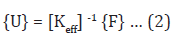
The total structure stiffness matrix [KT] is 15 x 15; but after accounting for the 3 support conditions at pole bottom (removing d.o.f. 1,2 and 3) reduces to [Keff], 12 x 12 (see Appendix 1).
Matrix Assembly and Solution
Equations (2) are assembled and solved on the matrix solutions module of MAPLE-16 computer program [26]. MAPLE is a general purpose software suite, similar to MATLAB, with powerful problem-solving algorithms in mathematics and engineering. Its numerical analysis module contains matrix operations capable of solving sets of equilibrium equations like those associated with the FEM.
The individual stiffness matrices [ke]i i = 1 to 4, of the 4 beam elements are computed using numerical values of parameters given in Tables 1, 2a & 2b. These element matrices are combined manually to obtain the total structure matrix [KT] and from which the effective stiffness [Keff] is extracted for input into MAPLE.


Applications
The above model is applied to two (2) composite poles each of total length 40ft. (12.2m), corresponding to the poles tested in the laboratory. Cross sectional properties are custom derived for each rebar configuration and the derivations are shown in Appendices 2a and 2b. Two specific cases are considered:
Case 1 – include rebars while calculating section Moment of Inertia
Case 2 – exclude rebars in Moment of Inertia.
(Note: The Moment of Inertia values of Case 1 implicitly assume that the modular ratio is 1.0. This is because, as mentioned earlier in the “Pole Testing” section, the individual moduli of HDPE and the fiberglass rebars are not known). The last two columns of Table 2b shows the values of Moment of Inertia computed.It is observed that for the poles studied the Moment of Inertia including rebars is 11% and 7.2%, more respectively, than that of the case without rebars.
No attempt is made to model the bond between the rebars and the pole material and complete adhesion is assumed. Only linear elastic behavior is considered. Second order effects (P-Δ), even though beneficial in a finite deflections environment, are not considered since they require use of a more powerful general purpose FE program.
Results
Table 3 shows the deflections from FE analysis of each of the poles and comparison with test data. Figure 4 & 5 show the load vs tip deflection plots of the two poles – both the test values as well as those from FE analyses. The poles were observed to behave elastically until the maximum test load. The almost straight-line pattern of the P-Δ plots indicates that the response of the system is linear.

Discussion of Deflections
The most important aspect of HDPE pole behavior is the resilience in sustaining of large elastic deflections without rupture. As discussed earlier, both test poles exhibited large deflections near failure load. This behavior is also noticed in the results of the FE analysis. Also, the test deflections are seen to be closer to FE values for Case 1 where rebars are included in the moment of inertia computations. For this case, the ratios of FE tip deflection to the pole length above ground are observed to be 0.397 and 0.296, respectively, for the two poles. This indicates good agreement with test results.
Serviceability Considerations
A cursory look at the deflections sustained by the two poles prior to collapse show that such lateral deformations are impractical in real-world operating or in-service conditions. While resiliency is advantageous in most other structural situations, deflections must be controlled for utility poles. Excessive deflections in transmission or distribution poles disturb the mandated clearances between conductor phases and lead to wire contact and short circuit outages. There is no industry consensus as to how much these pole deflections can be limited; but some current guidelines suggest limiting the pole top deflection to about 10% of pole height above ground (LAG) under conditions of short term lateral loading [1]. Some manufacturers also impose deflection limits while categorizing their pole classes [14]. We will adopt this criterion and evaluate pole structural performance for a deflection limit of 10% of LAG. This approach introduces a serviceability basis to design.
Table 4 shows the revised deflections Δser and flexural stresses fbser corresponding to serviceability load Pser. The bending stresses are now about ⅓ of those at failure. Figure 4 & 5 show the suggested pole load rating Pser based on serviceability considerations. Note that this rating refers to the 10% deflection limit; engineers can obtain other ratings depending on their project-specific deflection constraints.


Conclusion
A finite element (FE) model is developed to analyze the behavior of HDPE utility poles integrally reinforced with fiber glass rebars. The model is analyzed to determine elastic lateral deflections under specified tip loads. Pole cross section properties were explicitly derived for sections with 12 and 16 rebars. The model is validated by comparing deflections with those from fullscale tests and it is observed that the FE values agreed very well with tests. Inclusion of rebars in moment of inertia calculations appears to bring analytical values closer to test values.
The poles sustained large elastic deflections prior to failure, which, although attesting to the resiliency of the material, are impractical in real-world applications. Therefore, to introduce serviceability concerns into design, the maximum lateral load the poles can sustain for a deflection limit of 10% are evaluated. This helped establish a serviceability pole class rating.
The advantages of HDPE/FRP poles are many: higher strength-to-weight ratio than wood, steel or concrete, higher moment of inertia (relative stiffness EI) and substantially lesser weight, not to mention easier handling and environmentallyfriendly material. They hold great potential as an alternative to wood, steel and concrete poles. The technology can also have applications in the aerospace industry: fiber-reinforced flat plates, shells and other forms. This study is limited to just 2 poles and in order to generalize the inferences made here, further studies are warranted. It is also worth extending the investigations to truly geometric nonlinear behavior (i.e.) large deformation regimes as well as other potential aerospace applications.
Acknowledgements
The author wishes to acknowledge the assistance from Bedford Technology, Worthington, Minnesota with the test data on poles.
Appendix 1
Effective Structure Stiffness Matrix
Derivations of Pole Cross Section Properties
(a) 12 rebars
(b) 16 rebars
Nomenclature
θ = inclination of rebar to horizontal (See Appendices)
Δ = lateral deflection


References
- Kalaga S, Yenumula P (2016) Design of Electrical Transmission Lines: Structures and Foundations, CRC Press, USA, p. 426.
- Miller M, Hosford G, Boozer J (1995) Fiberglass Distribution Poles: A Case Study. IEEE Transactions on Power Delivery 10(1): 497-503.
- Polyzois D, Ibrahim S (2000) Development of glass FR plastic poles for transmission and distribution lines. Canadian Journal of Civil Engineering 27(5): 850-858.
- Sarmento M, Lacoursiere B (2006) A State of the Art Overview: Composite Utility Poles for Distribution and Transmission Applications. T & D Conference and Exposition, Caracas, Venezuela.
- (2017) Full-Scale Bending Tests of Bedford Technology HDPE Composite Utility Poles. EDM International, Test Report, Fort Collins, Colorado, USA.
- Polyzois D, Ibrahim S (1999) Performance of FRP Tapered Poles under Lateral Loading. Journal of Composite Materials 33(10): 941-960.
- Saboori B, Khalili SMR (2011) Static Analysis of tapered FRP transmission poles using FEM. Finite Elements in Analysis and Design 47(3): 247-255.
- Saboori B, Khalili SMR (2010) Transient Dynamic Analysis of tapered FRP composite transmission poles using Finite Element Method. Computers and Structures 92(2): 275-283.
- Masmoudi R, Mohamed H (2008) FE Modeling for Deflection and Bending Response of GFRP Poles. Journal of Reinforced Plastics and Composites 27(6): 639-658.
- Kadioglu F, Pidaparti RM (2005) Composite Rebars Shape Effect in Reinforced Structures. Composite Structures 67(1): 19-26.
- Fam A, Kim YJ, Son J (2010) A numerical investigation into the response of free and tubular composite poles subject to axial and lateral loads. Thin-walled Structures 48(8): 650-659.
- (2016) Composite Utility Poles – Electrical Transmission and Distribution. Creative Pultrusions, Alum Bank, Pennsylvania, USA.
- Lacoursiere B, Dutt V (2006) Composite Utility Poles: Advances in Design, Materials and Manufacturing. IEEE/PES T & D Conference Exhibition, Dallas, Texas, USA.
- (2008) Standard Composite Utility Poles. RS Poles, RS Technologies, Calgary, Alberta, Canada.
- (2003) Technical Overview. Shakespeare Composite Structures, Newberry, South Carolina, USA.
- (2003) Recommended Practice for Fiber-reinforced Polymer Products for Overhead Utility Line Structures. ASCE Manual 104.
- (2004) Design Manual for High Voltage Transmission Lines. RUS Bulletin 1724E-200, USDA.
- (2017) National Electrical Safety Code. NESC-C2-2017, IEEE, New York, USA.
- ANSI O5.1 (2008) American National Standard for Wood Poles – Specifications and Dimensions. New York, USA.
- (2018) Seapile Material Properties. Technical Data TL-10006 Rev. A, Bedford Technology Inc., Worthington, Minnesota, USA.
- (2018) Bar Force Material Properties, Technical Data, Bedford Technology Inc., Worthington, Minnesota, USA.
- (2017) Standard Test Methods of Static Tests of Wood Poles. ASTM D1036, American Society for Testing and Materials.
- Kalaga S, Weng Y, Neelam MK (2001) Nonlinear FE Analysis of a Column. Civil Engineering Today, ASCE-India Section.
- Przemeneicki S (1968) Theory of Matrix Structural Analysis. McGraw-Hill, New York, USA.
- (2016) Users’ Manual, MAPLE-16, Waterloo Maple, Ontario, Canada.
- Winter G, Urquhart LC, O Rourke CE, Nilson AH (1964) Design of Concrete Structures, McGraw-Hill Book Company, New York, USA.


