


Heat Transfer Efficiency in Coplanar Channels in Recuperative Heat Exchangers
Pelevin FV*
Submission: October 30, 2017 ; Published: December 14, 2017
*Correspondence author: F V Pelevin, Technical University BMSTU, Baumanskaya, Moscow, Russia, Email: pelfv@rambler.ru
How to cite this article: Pelevin F. Heat Transfer Efficiency in Coplanar Channels in Recuperative Heat Exchangers. Recent Adv Petrochem Sci. 2017;4(1): 555627. DOI: 10.19080/RAPSCI.2017.04.555627
Abstract
Achieving more efficient heat transfer in heat-transfer devices is a topical problem. Heat transfer and pressure drop in paths containing coplanar channels of different shapes are experimentally studied in this work. It is found that the mutual crossing angles of coplanar channels, finning ratio, and the dimensions of coplanar channels are the main parameters influencing heat transfer enhancement. The best effort from using coplanar channels is achieved at the values of Reynolds number Re=103-104. The coefficient of heat transfer in coplanar channels can be increased by a factor of 3-10 as compared with that for a smooth channel. The pressure drop coefficient increases with increasing the total mutual channel crossing angle. It is found that heat transfer in flat paths with coplanar channels becomes less efficient with decreasing the coplanar channel’s equivalent hydraulic diameter to 0.5-1.0mm, whereas more efficient heat transfer is obtained by fitting these channels with flow microturbulizers. It is shown that increasing the finning height in cylindrical paths with coplanar channels has no effect on vortex formation in them; however, it results in a higher finning ratio, due to which more efficient heat transfer is obtained.
Keywords: Coplanar channels; Heat transfer enhancement; Absolute channel dimensions; Heat transfer efficiency
Introduction
Traditional methods of heat transfer enhancement, such as increasing the coolant flow velocity and extending the heat transfer surface, sometimes give insufficiently good results. In view of this, heat-transfer paths with intricate configuration of the flow pass section are finding increasingly wider use [1-3]. A present, researchers again turn attention to a path containing coplanar channels [4-8]. The putting of gas-turbine engine (GTE) cooled blades with coplanar channels in serial production facilitated the development of this heat transfer enhancement method. A path containing coplanar channels combines two heat transfer enhancement methods: increasing the flow turbulence degree by flow swirling and increasing the heat transfer surface area due to finning. Paths made on an axially symmetrical surface, e.g., a cylinder and on flat profiled surfaces, e.g. a GTE blade are distinguished.
A path with coplanar channels is formed by parallel fins on the opposite surfaces of two shells conjugated with respect to the vertices of these fins. The fins of opposite shells are arranged at angle 2 β with respect to each other and form a system of mutually touching channels communicating to each other through diamondshaped cells on the surface of conjugated shells. Such a path can be made by means of the precision investment casting method, by mechanical processing, or using other technologies. Cylindrical (axially symmetrical) paths with coplanar channels are commonly used in compact high-efficient recuperative heat exchangers for different purposes.
Heat Transfer in Paths with Coplanar Channels
Investigations showed that the mutual crossing angle of coplanar channels 2 β is the main factor determining the value of heat transfer coefficient in a segment of stabilized heat transfer, the intensity of which increases with increasing the value of 2 β. The growth of heat transfer coefficient with increasing the angle 2 β can be explained as follows. Unlike the flow in channels with constant flow swirling ratio over the channel length (twisted tapes in the channel, etc.), coplanar channels interact in a certain conjugated region (a mixing region). With increasing the angle 2 β , turbulent pulsations (flow swirling) in the mixing region become more intensive.
This leads to a more intense exchange of momentums between the touching flows in channels, which, in turn, leads to a growth of tangential stresses in the conjugated region and to more intense mass transfer between the coolant flows due to a larger depth by which the turbulent flows penetrate from the mixing region toward the heat-transfer wall. The growth of tangential stresses in the conjugated region of channels leads to more intense mutual swirling of flows. As a result, a turbulent swirl flow with high transfer properties in the normal and tangential directions is produced in coplanar channels. The turbulence energy generated in the coplanar flow mixing region is transferred toward the heat- transfer surface with coolant flows both along the normal due to a growth of turbulent pulsations and tangentially with respect to the swirling flow as a result of additional mutual swirling. Thus, the boundary layer near the heat-transfer surfaces is continuously destroyed, and heat transfer in the near-wall layers is enhanced.
The enhancement of heat transfer can be characterized by the Stanton number St = α/(wcpρ), where α is the heat transfer coefficient, cp is the specific isobaric heat capacity, and ρ is the coolant density
The influence of Reynolds number on the Stanton number can be represented by the dependence St = A Ren. The exponent n remains almost constant in the entire variation range of Re number from 103 to 6 x 10⁴. This means that the coolant flow mode does not undergo any essential change in the studied range of Re numbers. Heat transfer in path containing coplanar channels will be more efficient and enhanced to a greater extent as compared with that in a smooth channel at low values of Re number This is because in case of a developed turbulent coolant flow mode (Re≥105) the flow turbulization degree is quite high both in smooth and coplanar channels. The results from investigations of heat transfer in annular paths containing coplanar channels have been generalized by the following criterion correlation [8]
St = exp(-2.47 + 0.81 )Re-0.32 Pr-06, (1)
where β is the angle expressed in radians.
The parameter χ (the fin height hf to the channel width a ratio) was varied in the range 0.25-1.1, the equivalent hydraulic diameter of the channels was varied from 2.17 to 2.6 mm, angle 2 β =45° -120°, Re =103 - 6 x 10⁴, and Pr=0.7. The relative error of determining the St number from formula (1) is ≥15%.
Owing to formation of vortices, the coefficient of heat transfer in coplanar channels can be increased, depending on the angle β , by a factor of 1.5-3.0 as compared with that in smooth channels. The parameter X has an essentially weaker effect on heat transfer At X =0.25-1.10, the formation of vortices has almost no effect on the St number unlike the effect from increasing the heat transfer surface. With a growth of parameter X, the finning ratio increases, as a results of which the overall efficiency of the path heat-transfer surface is increased:
Steff = StVCS η,
Where Steff and StVCS are the dimensionless effective (total) heat transfer and heat transfer during vortex formation in coplanar channels.
Owning to vortex formation, the heat transfer intensity is increased by a factor of 1.5-3.0 as the range 2 β is increased from 45° to 120°.
Pressure Drop in Paths Containing Coplanar Channels
Experimental data on the distribution of pressure over the length of paths with coplanar channels were used for determining the local pressure drop coefficients in the measured parts of the path between the sections with pressure taps using the Darcy equation

where Δp = pin - pout; Pin and pout, are the static pressures at the inlet to the path with coplanar channels and at the outlet from it, Pa; deq is the path equivalent hydraulic diameter, m; l is the distance between the pressure taps, m; and is the coolant motion velocity in the channel, m/s.
In the entire studied range of Re numbers, the variation pattern of pressure drop coefficients remains monotonic in nature, also in the transition flow mode region for smooth tube. This is an evidence of the fact that in paths containing coplanar channels the flow mode in the range of Re numbers from 103 to 106 x 104 does not undergo any essential change and is turbulent. Unlike the flow in a smooth tube, the self-similarity region of the pressure drop coefficient in the path with coplanar channels begins at Re = (1.0-1.5) x104. This conclusion holds true for all of the investigated path versions.
As the total mutual intersection angle of channels increases, so does the pressure drop coefficient. The larger the angle 2 β, the more rapidly the coefficient ζ grows. With increasing the angle 2β from 45° to 104°, the pressure drop coefficient increases by a factor of 5-6. The obtained experimental data has been generalized in the following form [8].

The relative error of generalization (2) does not exceed ±10%.
Taking the heat transfer enhancement and pressure drop into account, we find that the optimal mutual intersection angle of coplanar channels . 2β = 90°
This method for enhancing heat transfer by means of coplanar channels is especially efficient at Re = 103-104.
The Influence of Coplanar Channel Absolute Dimensions on Heat Transfer Efficiency
It should be pointed out that, all other things being equal, the absolute dimensions of coplanar channels may have an effect on the heat transfer intensity. Investigations of heat transfer efficiency in flay paths containing coplanar channels with the equivalent hydraulic diameters.
deq= 0.5 - 2.0mm showed that the heat transfer coefficient drops very rapidly deq as decreases. In the studies models, the fin height was equal to 0.8mm, the channel width was equal to 0.55mm, the fin thickness was equal to 0.63mm, and the angle 2β =30°, 60° and 90°. Grade 20 steel was used as material of the models. With such small sizes of the coplanar channels, the heat transfer in them for 2β =30° and 60° is almost equal to that in a smooth channel, and the pressure drop in them is a factor of 2.5-4.0 higher. The heat transfer in a path 2β =90° is a factor of 1.25 higher as compared with that in a smooth channel; however, a growth of pressure drop by a factor of 6.5 is observed.
Decreasing the hydraulic diameter of channels entails a decrease of mixing zone dimensions and flow turbulization degree, which leads to a growth of boundary layer thickness and drop of heat transfer intensity. For achieving more intense heat transfer, the coolant flow should be additionally turbulized within the confines of the boundary layer. The effect the interfin channel base has on heat transfer is insignificant with that of fin vertex surface. Measures should be taken for achieving a strong influence of the channel base on heat transfer enhancement.
The heat transfer becomes drastically less intense and the pressure drop coefficients increase as the equivalent hydraulic diameter of coplanar channels is decreased to 0.5-1.0mm. But it is exactly such channels that can be used in recuperative heat exchangers of chromium-nickel steel. Therefore, it is important to find a method for enhancing heat transfer in coplanar channels with a small equivalent hydraulic diameter. Additional turbulization of flow at the bottom of coplanar channels was obtained by cutting fins on the heat-transfer surface to a larger depth and by making recesses on the channel bottom. The depth of turbulizing grooves was equal to 0.1mm, which is approximately equal to the size of artificial roughness.
The heat transfer intensity became a factor of 1.7 higher, and the pressure drop increased by a factor of 2.3. This measure made it possible to increase the heat transfer efficiency in a flat path with coplanar channels by more than a factor of 3. The heat transfer enhancement efficiency Koff was determined from the following formula suggested in [3]:
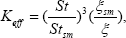
where Stsm and ζsm are the Stanton number and pressure drop coefficient in a smooth channel.
With flow microturbulizers installed in flat paths containing coplanar channels, the heat transfer efficiency is increased by approximately a factor of 3.4.
A heat exchanger made of metal having high heat conductivity is characterized by higher values of the parameter χ . In order to investigate the effect the parameter χ has on vortex formation at the bottom of coplanar channels, we carried out tests of a cylindrical path with coplanar channels and with the parameter χ =4. The fin height is 4mm, the fin thickness is 1mm, and the distance between fins is 1mm. The path is made of Grade LS-80 brass. With such geometrical dimensions of the heat-transfer path, its finning ratio is close to the maximum value. The experiments were performed in the Reynolds number variation range from 103 to 104. The mutual intersection angle of channels is 90°, and air is used as coolant.
For enhancing heat transfer in paths containing coplanar channels, we investigated a cylindrical “vortex” path ( χ =4) with cut fins on the heat-transfer surface. The organizing (outer) surface of the path with coplanar channels was not changed. Grade LS-80 brass was used as the heat transfer surface metal. The fin thickness is 1.3mm, the channel width is 1mm, and the fin height is 4mm. The fins are cut with the pitch S=12h. The depth of turbulizing grooves is h = 0.1mm and the cutter width was 0.8mm. As a result, the finned heat-transfer surface was transformed into a pin-studied surface.
Unlike flat “vortex” paths, the use of cut fins in the cylindrical “vortex” system did not yield more intense heat transfer. The value of Steff in such a combined (pin-studded and vortex) path does not exceed the Steff number in a purely “vortex” path with the parameter χ = 4. At low Reynolds numbers, the “vortex” path is even more efficient. For achieving additional flow turbulization, we tested a cylindrical path with coplanar channels on the bottom of which a longitudinal turbulized with the transverse sizes 0.15 x 0.15mm was made. No significant enhancement of heat transfer was obtained.
Thus, it has been found from the results of experiments on studying the efficiency of a heat-transfer path containing coplanar channels that the mutual crossing angle of coplanar channels and channel sizes are the main parameters affecting the heat transfer enhancement. This method of heat transfer enhancement is especially efficient in the range of Reynolds numbers Re = 103 - 104. The optimal mutual crossing angle of coplanar channels is equal to 90°. For achieving more efficient heat transfer in flat paths with coplanar channels, the coolant flow at the channel bottom should be turbulized.
References
- Roizen LI, Dul kin IM (1977) Thermal Calculation of Finned Surfaces. Energiya, Moscow, Russia.
- Kharitonov VV (1993) Thermo physics of Laser Mirrors. MIFI, Moscow, Russia.
- Kalininn EK, Dreitser GA, Yarkho SA (1981) Enhancement of Heat Transfer in Channels. Mashinostroenie, Moscow, Russia.
- Savostin AF, Tikhonov AM (1970) Studying the characteristics of plate heating surfaces. Teploenergetika 9: 75-78.
- Galkin MN, Popov VG, Yaroslavtsev NL (1985) Investigation and calculation of the hydraulic and thermal characteristics of cooled constructions containing coplanar channels. Izv Vyssh Uchebn Zaved, Mashinostroenie 3: 73-76.
- Kuznetsov ND, Kudryavtsev VM, Nagoga GP (1984) Heat transfer and pressure drop in paths formed by a system of communicating coplanar channels. Trudy MVTU 417: 54-75.
- Kudryavtsev VM, Orlin SA, Posnov SA (1983) Experimental investigation of pressure drop in annular paths containing coplanar channels. Izv Vyssh Uchebn Zaved Mashinostroenie 4: 54-58.
- Orlin SA, Posnov SA (1984) Experimental investigation of heat transfer and pressure drop in annular paths containing coplanar channels. Trudy MVTU 417: 9-22.


