


Research and Structural Optimization of Heat Dissipation Performance of Plate-Fin Heat Exchanger
Li Xiaoxiang1*, Wang Anlin1 and Zhang Jie2
1School of Mechanical Engineering, Tongji University, China
2Yantai Special Equipment Inspection and Research Center, Yantai, China
Submission:June 01, 2019; Published:July 12, 2019
*Corresponding author: Li Xiaoxiang, School of Mechanical Engineering, Tongji University, Shanghai,201804, China
How to cite this article: Li Xiaoxiang, Wang Anlin, Zhang Jie. Research and Structural Optimization of Heat Dissipation Performance of Plate-Fin Heat Exchanger. Robot Autom Eng J. 2019; 4(4): 555643. DOI: 10.19080/RAEJ.2019.04.555642
Abstract
Aiming at the problem of high oil temperature in a certain engineering machinery transmission system, a method to improve the heat dissipation performance of the heat exchanger by improving the internal structure of the heat exchanger is proposed, which makes it work in the normal temperature range. Based on the Colburn analogy equation and the fluid force balance equation, the influence factors of the heat dissipation performance of the water passage in the heat exchanger are analyzed. It can be seen that the cross-sectional area of the fluid passing through the fins is the most important factor affecting the heat dissipation performance of the heat exchanger. Comparing the heat dissipation performance before and after the improvement of the heat exchanger structure, the result shows that the heat dissipation power of the heat exchanger is increased by 18.3% ,and the oil temperature of the engineering machinery power transmission system is reduced by 19%,which effectively solves the problem.
Keywords:Heat exchanger; Colburn analogy equation; Structural optimization; Heat dissipation performance
Introduction
As a heat exchange device, heat exchangers are widely used in many fields such as automobiles, electrical and electronic equipment and engineering machinery [1-3]. The working environment of construction machinery is harsh, and its working time is very long. A good cooling system is a prerequisite for ensuring that the construction machinery works in the optimal temperature range, and the high temperature of the hydraulic oil caused by the failure of the heat exchanger is one of the factors that frequently cause the failure rate [4-5]. The heat exchanger is an important part of the cooling system in the power transmission, and its heat dissipation performance has an important influence on the oil temperature.
At present, the research on the heat dissipation performance of the heat exchanger is mainly on the external conditions and internal structure of the heat exchanger. The study of the external conditions of the heat exchanger is mainly in the aspects of atmospheric pressure, air density, fins gap and wind scooper [6-9]. In the study of the internal structure of the heat exchanger, part of the study is the analysis of the influence of internal structural factors on the heat dissipation performance [10-12], and the other part is to improve the heat dissipation performance by optimizing the internal structure [13-15].
In this paper, the oil temperature of a certain construction machinery transmission system is taken as the research object, and the internal structure is improved on the basis of the analysis of the influence factors of the plate-fin heat exchanger used. Through the improvement of the internal structure, the heat dissipation performance of the heat exchanger is improved, the oil temperature and heat balance point of the mechanical transmission system is lowered, and the problem of high oil temperature is effectively solved.
Problem and Test
When the ambient temperature is about 25°C, the oil temperature rises gradually after one hour of operation, and the maximum temperature exceeds 130°C, which is higher than the design requirement of 110°C. After inspection and testing, it can be known that:
1. The air flow of the water tank meets the design requirements.
2. No wear points are found between the key components, and there is no interference between the brake mechanisms.
3. The water circulation in the engine is parallel with the heat exchanger, the inlet water temperature of the heat exchanger is maintained at 90±1°C.
4. The water flow meets the requirements.
5. The inlet and outlet pressure of the torque converter meets the standard value, the internal leakage flow is less than 5L/min.
6. The temperature of other parts of the machine is not high.
Under the condition that the test conditions are consistent with the working conditions of the construction machinery, the heat dissipation performance of the heat exchanger was tested. The test is shown in Figure 1 and the data is shown in Table 1.


According to the above data, the heat dissipation power of the heat exchanger is about 46.5kW, which is less than the theoretical design requirement of 50kW. Therefore, the heat dissipation performance of the heat exchanger needs to be improved.
Modeling and Analysis
The internal structure of the heat exchanger used in this paper is shown in Figure 2, where A is the water inlet, B is the water outlet, the side is the two oil inlet ports, the b side is the two oil outlets, and c is the partition

There are many factors affecting the heat dissipation performance of the heat exchanger, including the number of fins and its internal structure, the overall layout of the fins, the water flow direction and the contact area between oil and water. The heat transfer coefficient equation (1) of the cold fluid passage is analyzed while maintaining the total fin structure.
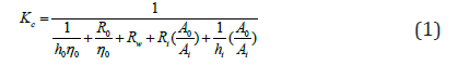
Where Kc denotes the total heat transfer coefficient of the cold fluid channel, h0 denotes the heat transfer coefficient between the cold fluid and the wall surface. hi denotes the heat transfer coefficient between the hot fluid and the wall surface, Ri denotes the thermal resistance of cold fluid fouling, R0 denotes the thermal resistance of hot fluid fouling, Rw denotes the wall thermal conductivity, A0 denotes the total surface area of the rib side, Ai denotes the ribless side surface area, η0 denotes the total efficiency of the ribs.
Under the condition that the structure of the outer shell of the heat exchanger, the thermal fluid and outside the fin remain unchanged, hi, Ri, A0, Ai and η0 can be regarded as constant. When R0 is equal to 0.000176 m2·℃/W, the equation (1) can be simplified.
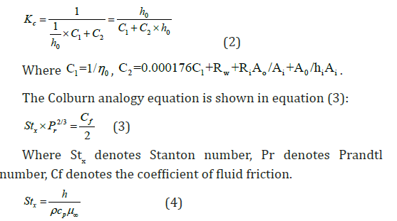
Where h denotes the heat transfer coefficient, ρ denotes the fluid density, cp denotes the fluid equal pressure specific heat capacity, and μ∞ denotes the fluid mainstream speed.
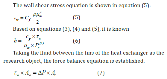
Where Aw denotes the heat dissipation area of the heat exchanger fins, △P denotes the pressure difference between the fin inlet and outlet, and Ac denotes the effective sectional area which the fluid passes between the fins.
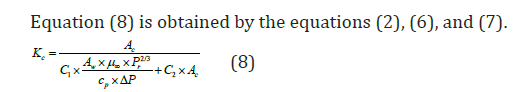
When the water temperature is 90°C, cp is equal to 4199 and Pr is equal to 2.03. According to the structure of figure 2 and its related parameters, it is known that △P is equal to 106Pa, Aw is equal to 6 m2, and h0 is equal to h. Assuming that μ∞ is a fixed value, equation (9) can be obtained on the premise that the heat exchanger water flow, fin structure and gap remain unchanged.
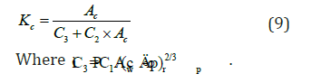
The relationship between Kc and Ac is shown in figure 3. According to formulas (5) and (7), Ac is proportional to τw, It can be seen from Figure 3 that increasing Ac can effectively improve Kc within a certain range.

Structural Improvement and Verification
The internal structure of the heat exchanger is improved while maintaining the heat exchanger outline structure, the original fin structure and the installation position unchanged. The improved structure is shown in Figure 4. It can be seen that the structure can effectively increase the effective area of fluid passage between the fins.


The experimental conditions for the performance test of the heat exchanger are the same as in section 2. The heat dissipation performance data of the improved structure is shown in Table 2. The heat dissipation power is increased from 46.51kW to 55.01kW. The heat dissipation power is increased by 18.3%, which satisfies the design requirements. At the same time, the improved heat exchanger was tested by operation, and the oil temperature of the transmission system was reduced from 130℃ to 105℃, which effectively solved the problem.
Conclusion
Based on the analysis of the influence factor of the heat transfer coefficient Kc of the cold fluid passage, it can be seen that increasing the cross-sectional area Ac of the cold fluid passage can effectively improve the heat transfer coefficient Kc of the cold fluid passage, which has engineering application value for the optimization of the heat exchanger structure.
The heat dissipation power of the improved heat exchanger is increased by 18.3%, and the oil temperature of the engineering machinery transmission system is reduced by 19%, which satisfies the use in the normal temperature range and solves the major problem.
References
- Wang Boya, Zhu Kai, Cui Zhuo, Wei Jie (2017) Effect of the water-outlet mode on the heat transfer performance of water-cooled chip heat sink. Journal of Refrigeration 38(06): 49-54.
- Wang Boya, Zhu Kai, Cui Zhuo, Wei Jie (2017) Influence of the location of the inlet and outlet on the chip heat sink. Journal of mechanical engineering 54(10): 188-194.
- Miu Xuanhe, Huang Mengke, Zhang Birong, Fan Mingan (2017) Discussion on the application of incline type radiation system to the loader. Construction machinery and equipment 48(11): 9-12.
- Ji Yunlong, Ren Dongjie (2016) Reasons and solutions for excessive temperature of hydraulic oil of D11T bulldozer. Construction machinery & maintenance 3: 55-56.
- Hu Jingliang (2019) D8T bulldozer radiator structure improvement. Construction machinery & maintenance 3: 70-72.
- Xu Xiang, Suo Wenchao, Yang Dingfu, Dong Surong (2018) Heat Transfer Simulation of Vehicle Heat Exchanger in Plateau Environment. Journal of System Simulation 30(08): 335-342.
- Xu Zishun, Yu Hua, Yan Yunqiao, Pan Chengfei (2016) Study on flow characteristics of loader radiator based on CFD. Agricultural equipment & vehicle engineering 54(2): 5-8.
- Zhang Bofeng, Suo Jianqing, Wang Fenglan (2017) Study on influence of safety gap on heat dissipation performance of radiator. Agricultural equipment & vehicle engineering 11: 95-99.
- Chen Jinyou, Yang Lin, Qi Bo (2016) Study on effect of Fin-tube Arrangement on the Heat Exchange Performance of Fin-tube Radiator. Jiangsu Science & Technology Information 2: 61-63.
- Li Jia, Jin Sunmin, Yue Liang, Jin Ying (2015) Influence of inclination and filling ratio on the temperature distribution of plate-fin heat pipe radiator’s cold substrate. Fluid machinery 43(11): 82-86.
- Guo Jianzhong, Wu Jiajin, Zhang Qilin, Zhang Huawei, Mao Yong (2019) The analysis for radiator performance with variable angle fin. Modern Manufacturing Engineering 3: 1-5.
- Zhang Haijuan, Wang Xia, Lu Chenyan (2018) Zou yong. Comparative study on the performance of fin radiator and acicular radiator. Henan Science and Technology 651(17): 62-64.
- Zhu Mantao, Tian Chunhu, Xu Xiaoming, Li Na (2019) Optimization design of radiator fin performance based on RSM. Modern Manufacturing Engineering 3: 74-80.
- Suo Wenchao, Xu Xiang, Geng Fei (2017) Optimization of radiator core shape of vehicle engine based on CFD. Acta armamentarii 9: 178-183.
- Kong Yongmei, Zhao Shuxing, Tian Rui, Mao Qianming, Du He (2017) An orthogonal experimental design of forced convection finned tube applied in the radiator structure optimization. Journal of Tianjin Chengjian University 5: 55-58.


