


Self-Adjusting Fluid Drive of Translational Module of Manipulator
Konstantin Ivanov*
Department of Aerospace Control Systems, Almaty University of Power Engineering and Telecommunication, Kazakhstan
Submission: February 03, 2018; Published: April 13, 2018
*Corresponding author: Konstantin Ivanov, Department of Aerospace Control Systems, Almaty University of Power Engineering and Telecommunication, Baitursinov Street, 126, Almaty, 050013, Kazakhstan, Email: ivanovgreek@mail.ru
How to cite this article: Konstantin I. Self-Adjusting Fluid Drive of Translational Module of Manipulator. Robot Autom Eng J. 2018; 2(5): 555597. DOI: 10.19080/RAEJ.2018.02.555597
Abstract
Now in fluid engineering the fluid drives with one degree of freedom are used. Such drive provides univocal constraint between input and output links motion. However it is necessary to use the variable transfer ratio between input and output links for overcoming of variable resistance force and inertia forces. Use of electronic control systems for force and volume regulating leads to extreme complication of drives, decrease of their reliability, raise of manufacturing cost and service. Recently the principle of creation of the fluid-flow self-controlled mechanism by use of fluid system with two degree of freedom has been developed. In the paper the compact Self-adjusting mechanism which provides force self-regulation without a control system is developed on this principle.
Keywords: Fluid drive; Self-regulation; Fluid self-adjusting mechanism; Closed fluid contour; Manipulator
Abbreviations: CSA: Canadian Space Agency
Introduction
The fluid drives of translational motion are intended for transfer of motion from the pump to executive tools of manipulators. The control, change of speeds and reverse are controlled and automated by means of fluid drives [1].
Now in fluid engineering the fluid drives with one degree of freedom are used. Such drive provides univocal constraint between input and output links motion. However for overcoming of variable force of resistance it is necessary to use the variable transfer ratio between input and output links. The adjustable fluid drive should contain a complex fluid control system.
Canadian Space Agency (CSA) engineers have developed an innovative method for the emulation of electrical actuation by using fluid actuators for robotic systems. Inventor Wen- Hong Zhu has created the Self-adjusting Output Force Tracking Control Device of Fluid Cylinders [2]. From this invention a commercial product was created that has a control algorithm, including a software package. This product also offers a sophisticated parameter tuning procedure for Self-adjusting control of fluid actuators and ancillary equipment for robotic applications.
The presented control system contains the strain sensors taking into account the Coulomb -viscous friction, the control unit of output force, the feedback, the device of updating of the friction model parameters etc. Such control system appears too complex and does not provide the instant reaction and adequate work.
Use of systems of electronic control for force and volume regulating leads to extreme complication of drives, decrease of their reliability, raise of cost of manufacturing and service.
The electronic control system should contain in fluid engineering numerous sensing transducers, amplifiers, feedback systems, converters of signals etc. Fluid engineering should use adjustable valves, butterfly governors, slide valves, pressure regulators etc [1].
The operated fluid engineering represents the most complicated mechanical system. Such system demands constant adjustment to working conditions. It is not capable to provide absolute and continuous adequacy of motion of an end effector to a variable load with an inertia forces. Such fluid system has changing temperature properties of a liquid, a friction and other factors.
The operated fluid engineering has low reliability, high cost and demands highly skilled service.
Recently the principle of creation of the fluid-flow self-controlled mechanism on the basis of use of the closed stream in system with two degree of freedom has been developed [3,4].
Ivanov K.S. has developed and has taken out a patent for the Self-adjusting fluid-flow mechanism [5]. However in the presented aspect the mechanism is difficult for practical purposes using because of the big sizes and inconsistency of movements of links in the presence of two degree of freedom.
The purpose of the present work is to develop the compact circuit design of the self-controlled Self-adjusting fluid-flow mechanism in which the co-ordinated motion of links takes place.
Researchers are executed on the basis of mechanics and Fluids laws.
Description of the Self-adjusting Fluid Mechanism
The self-adjusting drive of the piston of the fluid mechanism is presented on Figure 1.
The drive contains input reservoir , output reservoir , the input piston 1, intermediate blocks of pistons 2-4 and 3-5 and output piston 6. Pistons 1, 2, 3 are placed in cylinders of input reservoir . Pistons 4, 5, 6 are placed in cylinders of output reservoir . We will denote - the squares of pistons. - Speeds of motion of pistons.

Blocks of pistons 2-4 and 3-5 together with reservoirs and create the closed fluid contour placed between the input piston 1 and output piston 6.
Motive force is acting on the input piston. Resistance force is acting on the output piston. In an operating time the force on the input piston 1 creates pressure in the input cylinder and moves blocks of pistons 2-4 and 3-5. Pistons 4 and 5 create in the output cylinder pressure and move the output piston 6.
The closed fluid contour provides adaptation of system to output loading.
Only in stroke is considered on Figure 1.
Interconnection of Parameters of the Fluid Mechanism
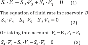
Let's compile the equations of fluid rate in reservoirs A and B.
The piston 1 is moving to the right. The block of pistons 2-4 is moving to the right, because . The block of pistons 3-5 is moving to the left, because . The piston 6 is moving to the right. We will consider the positive speed directed into the reservoir.
The equation of fluid rate in reservoir A.
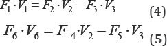
Let's multiply the equation (1) on and P1 the equation (3) on P6 . Taking into account p .S=F we will receive after commutations
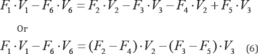
Let's subtract the equation (5) from the equation (4), we will receive
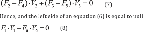
The left side of an equation (6) represents an algebraic sum of powers of external forces. The right side of an equation (6) represents an algebraic sum of powers of internal forces. If the fluid system is in equilibrium then according to a principle of virtual works the sum of powers (or works) of internal forces in the presence of ideal constraints is equal to null.
The equation (8) represents additional analytical constraint between parameters of the fluid system with two degree of freedom. This constraint imposes restriction on motion of links of system and provides definability of system at presence only one input.
The equation (8) allows determining of the output speed V6 on the given constant input power P1 =F1.V1 and on the given variable output resistance force F6
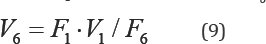
The equation (9) defines brand new property of a fluid system with two degree of freedom - fluid adaptation. At any given output force of resistance F6 the output speed V6 accepts automatically matching value. The fluid system with two degree of freedom is independently accommodated for external loading without use of any control system. External loading is controlling by output speed. Such fluid system is selfcontrolling system.
The closed contour in a fluid system with two degree of freedom creates brand new precedent: it first, imposes the additional constraint leading to definability of motion, and secondly, creates effect of force adaptation.
In the equation (7) we will denote F35 = F3 — F5 - full force on the block of pistons 3-5, F24 = F2 — F4 - full force on the block of pistons 2 - 4. We have: —F53 = F5 — F3 , because F5 > F3 . Then from the equation (7) we will receive
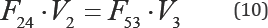
The equation (10) represents the equation of internal circulating energy. Internal forces F 53,F24 generally are not equal among themselves; however the equilibrium is performed by a principle of virtual works at the expense of speeds.
We will determine the internal speeds V3,V2 of blocks of pistons 3-5 and 2-4 by solving system of the equations (1), (3) on known values of speeds V1,V6 . Speed V1 is given, and speed V6 is determined from the equation (9).
Let's multiply the equation (1) on SZ and the equation (3) we will multiply on S3 . We will receive
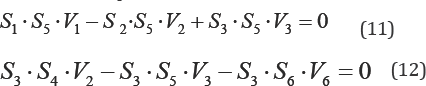
Let�s add the equation (12) with the equation (11), we will receive
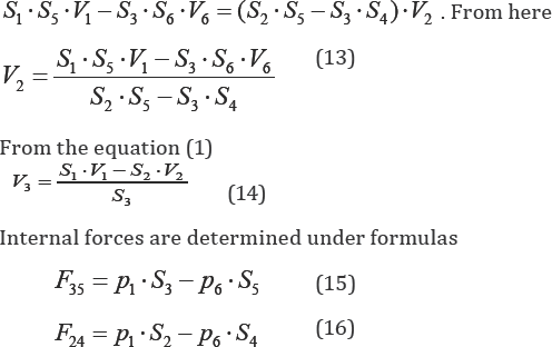
It is possible to perform the check of balance of circulating energy on the equation (10), using the formulas (13), (14), (15), (16).
From the equation (8) it is following 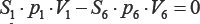 From here we will receive constraint between pressures in reservoirs A and B
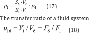
At constant input power the transfer ratio is depending on the variable output force of resistance .
Compact Self-Adjusting Fluid Drive
The Self-adjusting fluid drive has been developed earlier for the module of manipulator [3,4]. However this drive had the complex design and did not provide conservation of the fluid rate balance on direct stroke and back stroke.

The compact Self-adjusting fluid drive (Figure 2) matches to the Self-adjusting drive of the piston (Figure 1), is executed under the compact circuit design [5] and provides a conservation of the fluid rate balance on direct stroke and back stroke.
Designations of basic parts of this drive completely match to drive designations on Figure 1.
The drive contains input basin , output basin , input piston 1, intermediate block of pistons (converter) 2-4, intermediate block of pistons (converter) 3-5, output piston 6 and return springs 7 and 8. (It is necessary to note, that the piston 1 can be removed from a mechanism design).
Each intermediate block of pistons is executed in the form of the piston, having two various contact surfaces with a liquid in basins and .
Pistons 1, 2, 3 are placed in input basin . Pistons 4, 5, 6 are placed in output basin . Input and output pistons are connected with a pump feeding system of a liquid. We will use former designations: - squares of pistons. - speeds of pistons motion.
Work of the compact return Self-adjusting fluid drive on direct stroke is analogous to work of the Self-adjusting drive of the piston (Figure 1). In an operating time the drive makes a return translational motion of the executive tool together with the piston 6.
At performance of back stroke the return springs 7 and 8 result a Fluid system in an initial position and provide balance of the fluid rate between basins and . Return springs provide the co-ordinated motion of links on direct stroke and back stroke.
Compact fluid-flow Self-adjusting drives of the module of the manipulator and gripper are developed in [3,4]. The Self-adjusting fluid mechanism possesses unique property. It is capable to work as in a regime of self-regulation with two degree of freedom, and in an extreme regime with one degree of freedom. The extreme operating mode occurs, when the maximum loading exceeds maximum permissible value. In this case the target piston of the mechanism is shut down, and the mechanism passes in a condition with one degree of freedom when the entrance piston continues traffic in some limits. It is possible to name such operating mode a stop regime. The stop regime allows avoiding mechanism breakage at an overloading. The overloading leads to a stop of the tool with possibility to continue work after overloading elimination, or after change of working conditions. Mechanism transition in a stop regime occurs automatically without control system use. One of possible alternatives of use of a stop regime is an self- adjusting fluid actuator of the manipulator gripper.
Regularity of interconnection of parameters of the compact Self-adjusting Fluid mechanism completely matches to the analytical regularity of interacting of parameters resulted above.
Mechanism synthesis consists in definition of the squares of pistons cross-sections on the set range of transfer ratios and also in definition of rigidity of return springs on a condition of maintenance of retrace of pistons into an initial position after the return termination.
Conclusion
The self-controlled compact Self-adjusting fluid drive working without a fluid control system and without an electronic control system provides absolute adequacy to variable force loading.
The self-adjusting fluid drive is extreme simple in design. Efficiency of perfection of fluid mechanism is not consisting in boundless complication of computer control, but in use of unprecedented properties of mechanics.
Undoubtedly fluid self-adjusting systems will find wide application in all branches of engineering, especially in modern robotics because the use of paradoxical properties of mechanics allows gaining the elementary, compact, reliable and adequate fluid drive instead of the usual fluid cylinder equipped with the most complicated and expensive control system.
References
- Cundiff JS (2001) Fluid Power Circuits and Controls: Fundamentals and Applications. CPC Press. Boca Raton London New York Washington, DC, P. 560.
- Zhu WH and Piedboeuf JC (2004) Self-adjusting Output Force Tracking Control of Fluid Cylinders with Applications to Robot Fluid engineering. Journal of Dynamic Systems, Measurement, and Control 127(2): 206-217.
- Ivanov KS (2014) Self-adjusting Robotics. Applied Mechanics and Materials. ICMERA 2014. Springer. Switzerland 656 (2014): 154-163.
- Ivanov KS, Tultayev B (2016) Self-adjusting Fluid Drive of Manipulator. Applied Mechanics and Materials 841: 215-220.
- Ivanov KS (2015) Drive of piston of fluid mechanism. Innovative patent of RK. No 29866. Min. Justice of RK, Astana, Bull 15: .


