


A People-Following Mobile Robot Using Kinect and a Laser Scanner
Ching-Long Shih* and Chao-Cheng Li
Department of Electrical Engineering National Taiwan University of Science and Technology, Taiwan
Submission: November 25, 2017; Published: January 30, 2018
*Corresponding author: Ching-Long Shih, Department of Electrical Engineering National Taiwan University of Science and Technology, Taipei, Taiwan, Tel: 1-886-2-2737-6706; E-mail: shihcl@mail.ntust.edu.tw
How to cite this article: Ching-Long S, Chao-Cheng L. A People-Following Mobile Robot Using Kinect and a Laser Scanner. Robot Autom Eng J. 2018; 2(1): 555578. DOI: 10.19080/RAEJ.2018.02.555578
Abstract
This research proposes a people-following mobile robot system that is equipped with Kinect RGB-D camera and a laser scanner, in which the Kinect’s skeleton tracking function helps, identify people in the depth image. First, the system selects a person who raises his two hands as the target to follow. Second, the system identifies the target to follow from the person’s location and color characteristics of clothes. When an occlusion occurs, the system uses the information from the laser scanner to guide the motion of the mobile robot and tries to re-recognize the target to follow at the same time. The people-following mobile robot accomplishes a human detection and follows only the target even if more than two people are located around the target person. The research conducts several experiments and shows the effectiveness of the proposed system to identify and follow a human in an indoor environment.
Keywords: Mobile robot; People-following; Kinect camera; Laser scanner; Human skeleton detection; Gesture recognition
Introduction
The ability to detect human motion, gestures, and behavior is an important task for service robots [1]. A robot that can carry luggage and follow a customer can be very helpful in many situations. Such a service robot should be able to interact with people and co-exist with people in a crowded environment designed basically for humans. Equipped with cameras, a robot can obtain images of the environment where it is situated through visual sensors and with the ability of visual perception can recognize objects and determine their locations. However, using only a 2D image is very difficult to identify or track the target in a 3D world. Kinect is a RGB-D camera combining a RGB image and a 3D depth image that can recognize the movement of a human. Kinect can extract the 3D positions of a human body’s joints, which can then be further processed to recognize human gestures. Kinect has been applied in various application fields such as health care, sport training, gaming, security, 3D construction, human motion recognition and many others. For instance, Kinect technology has been found to be very useful in various healthcare related services, such as physical therapy exercises, sport rehabilitation games, motor skill training, monitoring patient activities, medical operation room assistance, and other clinical areas [2].
Kinect (Kinect for Windows SDK V2.0) is able to track the skeletons of multiple persons by using only their depth image, and so it can be very easy to create gesture-driven applications [3]. Kinect can track at most 25 joint points of a human body skeleton and up to 6 persons at the same time. With the availability of tracking a human body’s skeleton joints positions and orientations for each user, the task of feature extract becomes much easier. One only needs to determine which joints are the most important for each activity.
Gesture recognition can be broadly categorized into gesture detection, pose estimation and gesture classification. Hand gesture detection is even a critical factor in sign language understanding. Because a hand is a smaller part in the human body, so detection and classification of hand gestures may be even more complex. In general, to develop a useful Kinect application involving human motion recognition, the following steps are typically required:
o Real-time human skeleton tracking;
o Recognition of the semantics of the activity or gesture formed by the motion; and
o Actions triggered by the detection of the particular motion.
There are many more reports of useful applications of Kinect in mobile robot systems. A Kinect based people- following mobile robot system was designed with its mission to keep the person in the centre of depth images and in at a fixed distance away from the mobile robot [4]. An autonomous robot equipped with 3 Kinects was built to follow and track a person [5]. The system selected a person who raised a hand as the target to follow at the beginning. The system could then identify a person from the person's location and characteristics of clothes and re-recognize the target to follow when an occlusion occurred. A Kinect was installed in a mobile frame at a height of around 120cm [6]. The system utilized color, depth, and skeleton frames from Kinect to find and track people for basic robotic movements like wander around and follow- me. Kinect was found useful in building an indoor map. For instances, Kinect and a laser range finder were used together to acquire environmental 2D map information [7]. In addition, 3D point cloud data from Kinect were transformed into an enhanced 2.5D and then down to a 2D grid map [8].
For the first step toward an autonomous service robot, we study a people-following mobile robot system, which is equipped with Kinect RGB-D camera and a laser scanner. Kinect is used to track human skeletons and to identify people from the depth image. The system selects a person who raises his two hands as the target to follow at the beginning. The system then identifies the target to follow from the person's location and RGB color characteristics of clothes. In the case of target occlusion, the system switches over to use the information from a laser scanner to plan the robot motion [9]. The robot is a two-wheel differential driven mobile robot controlled by a FPGA controller operating in a closed-loop speed PI control with a built-in encoder odometer to record its pose (position and orientation).
System Overview

The experimental people-following mobile robot system as shown in Figure 1 includes mainly a differential-drive mobile robot platform, a Kinect camera V2, a laser scanner SICK 200, a notebook computer, and a 24V lithium polymer battery. The mobile robot platform consists of two independent driving wheels and two free wheels. The actuator of the driving wheel is the dc motor with gear and encoder, which is in velocity PI control. The radius of driving wheel is r=75mm, and the distance of two driving wheels is 2L, where L=20mm. The wheel is actuated by a dc motor (motor maximum no-load speed 3000rpm) with a 17:1 gear reducer, and the motor encoder has a resolution of 68,650ppc. The motor speed control system is built on an Altera DE0-nano FPGA development board running at a system clock rate of 50Mhz. Motor speed PI control and series communication modules are implemented using Verilog HDL and synthesized by an Altera Quartus II EDA tool. The Kinect camera processing and connected curve generation programs are programmed in Visual C++ for PC.
Define to be the position of the middle of the two wheels in the world frame {W}. The origin of the robot base frame {B} is assigned to the middle of the two driving wheels, and is the yaw angle of the x-axis of the robot frame with respect to the x-axis of the world reference frame, as shown in Figure 2. Thus, is the pose (position and orientation) of the mobile robot in the world coordinate frame Figure 2. Coordinate frames of the mobile robot system: the world frame {W}, the robot base frame {B} with origin at the middle of the two driving wheels, and the Kinect coordinate frame {K}.

A Kinect V2 camera is installed at the upper middle of the free wheels of the mobile robot. The Kinect has two cameras, the left one is the RGB camera to obtain color images, and the middle one is the IR depth camera. The RGB color image has a resolution of 1920x1080 at 30 frames per second. The IR depth (D) image is 16-bit (in mm) at a resolution of 512x424, and the sensor range is between 0.5m and 8.0m at 30 frames per second. The depth of each pixels is computed based on the phase shift of the emitted modulated light and corresponding reflected light. The Kinect coordinate system {K} is centered on the Kinect's IR sensor as shown in Figure 2, in which the Y-axis points upward, the Z-axis points where the Kinect is pointing, and the X-axis is to the left (or cross-product of Y-axis and Z-axis). In this work, the Kinect is used mainly for human motion tracking and recognition as well as target person detection.
A laser scanner, SICK S200, is installed at the front end of the robot platform. Its main function here is to avoid obstacles such as doors, walls, and people. The principle of a laser scanner is based on time- of-flight. It can scan a range of 270 degrees in a resolution of 0.5 degrees and returns 16-bit distance values between 1.0cm and 800cm. For practical reasons, only 120 degrees of a scanned range are used here as shown in Figure 2. The laser range data’s updating time is 0.5 seconds.
Figure 3 shows the overall system block diagram of the people-following mobile robot control system. The system's operation is according to two external sensors (Kinect & laser scanner) and internal sensors (motor encoders). When the Kinect system is successful at detecting and tracking the target person, the mobile robot follows his steps; otherwise, the mobile robot is guided by the laser scanner to avoid local obstacles and tries to return to the state of tracking the target person. The mobile robot's pose trajectory history is recorded from motor encoder odometry.

Target person recognition and detection
Human motion tracking and recognition
One of the most important Kinect features is body tracking, as the Kinect can track a total of 25 skeletal joints per person. With Kinect for Windows SDK V2.0 one can extract the 3D positions of a human body's joints, which can then be further processed to recognize human gestures. In this work, we used the data of a body skeleton: joint rotations, positions and angles between joints for tracking and recognition of the target person to follow. The system only selects the person who raises his two hands as the target to follow. Here, we build a Kinect application system using only a single depth image to supports the following human motion tracking and recognition tasks:
Step 1: Record the sequence of hand-raising gestures (Figure 4) by using Kinect Visual Gesture Builder in Kinect Studio, which is used to identify the target to follow.

Step 2: Track human body skeletons up to 6 persons (called body frames) at the same time.
Step 3: Compare body gestures with the recorded target sequence and return a confidence value between 0 and 1. A confidence value of 0.95 indicates that a target person is successfully identified. A RGB model image is saved for target person detection later.
Target person detection

Target person detection is based on a comparison of color characteristics of his clothes in a body ROI (Region-of-interest) as shown in Figure 5. The body ROI of size 250x250 is formed from 4 human body joints in a detected human skeleton: spine base, shoulder right, shoulder left and spine shoulder. First, the RGB image, 0 ≤ R,G,B ≤ 255 , is transformed to the HSV image, 0 ≤ H ≤ 180 , 0 ≤ S ≤ 255 , and 0 ≤ V ≤ 255 . To compare two histograms, the histogram I from the input image and the histogram M of the model image, a metric of intersection d (I, M) is used to express how well both histogram match, whereby
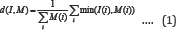
When, d(I,M) ≥ 0.25 , it indicates that the target person is detected successfully. In summary, the program flowchart of human motion detection and target person detection is shown in Figure 6.

People Following Motion Planning
Mobile robot motion planning by tracking target person
Let v and ω be the instantaneous linear velocity command of the origin and angular velocity command of the robot base frame, respectively. Let (xc, xc, zc) be the detected neck joint point of the target person in the Kinect coordinate frame {K}. Define  to be the angle of the target person with respect to the robot base frame. The mobile robot motion command ( v and ω ) is planned according to target tracking position (xc,xc,zc) . The linear velocity command v is a nonlinear function consisting of linear segments, dead-zones and saturations as below,

Where, parameters zmax = 300 cm, zmln = 150 cm, z1 = 30 cm, z0 = 45 cm, vmax = 27.5 cm/sec, and vmln = 20.6 cm/sec. Similarly, the angular velocity command ω is planned as below,

Mobile robot motion planning by laser scanner
The above target tracking planning strategy will fail whenever the vision system fails to update the new location of the target person. In such a case, the laser scanner is used to resolve the difficult situation. The range data s (in cm) of the laser range scanner in a range of 120 degrees as shown in Figure 2 are rewritten as
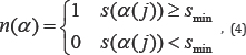
Where, α = 0.5 (j — 271) degrees, 151 ≤ j ≤ 391 and safety threshold smln = 70 cm. The value of n(α) = 1 denotes that the line of sight at an angle of α relative to the x-axis of the robot's base frame is free of any obstacle; otherwise, n(α) = 0 denotes that there is an obstacle in this direction angle. Let θ* be the previous target tracking angle (relative to the x-axis of the world frame) just before a failed detection of a new target object occurs, and θ is the current mobile robot's orientation angle.
The mobile robot now plans to move forward, if n(α) = 1 , for -45° <α< 45° , and cos(θ-θ')> 0 ; otherwise, the robot rotates in place counter clockwise (or clockwise) if there is more free range in the left-side than the right-side (or the right- side than the left side). The above procedure is repeated until the target object is verified and detected again. Figure 7 shows the program flowchart of guidance by a laser scanner. Because the robot always maintains a minimum safety distance of 70 cm in its front end and its only mission is to follow the target person, it therefore seldom needs to consider the problem of obstacle avoidance when the target object is in front of it.

Experimental Results
During the experiments, the maximum robot's speed is set to 25.5cm/sec and the target's proximity distance to 30 cm for the safety reason. In the first people-following experiment, there are two persons around the target person. First, a person raises his two hands to be assigned as the target to follow. The mobile robot then identifies and tracks the target to follow from the target person's location and color characteristics of his clothes. The people-following mobile robot accomplishes a human detection and follows only the target of following even if more than two people are located around the target person. Figure 8 shows multi-shots of the first people-following mobile robot experiment. Multi-shots of the first people-following mobile robot experiment; the target person identification is performed right before t = 0 sec.; and tracking the target person starts right after.

In the second people-following mobile robot experiment, there is one person walking through the space between the mobile robot and the target person during the experiment. The mobile robot accomplishes the target person identification and detection and successfully follows only the target person even if a person is walking across between the mobile robot and the target person. Figure 9 shows multi-shots of the second mobile robot experiment. At time t = 21sec. a person appears in the front of the robot and an occlusion occurs, the system re-recognizes the target person after the breaking person who appeared walks away from the robot.


In the third example, the mobile robot accomplishes the task of following the target person to walk through a hallway and through doors inside an office building. Figure 10,11 show multi-shots and the mobile robot trajectory of the third people-following experiment, respectively. Whenever the target person walks inside a door, an occlusion easily occurs. The system always re-recognizes the target person after the robot passes through the door by using the information from the laser scanner. In summary, the experimental robot system recognizes the target to follow successfully on more than 95% of the trials and the target person recognition time is less than 0.1 seconds.
Conclusion
This paper has proposed a people-following mobile robot system based on a Kinect sensor and a laser scanner. The robot is able to follow a target person if that person is identified through Kinect. When the target person disappears, the robot uses the range information obtained from a laser scanner to plan its motion and to re-recognizes the target person at the same time. The experimental results show that the people-following mobile robot accomplishes the task of tracking only the target person to follow even if more than two people are located around the target person or the mobile robot. Furthermore, the mobile robot also accomplishes the task of following the target person to walk through a hallway and through doors inside an office building. In our experiments, the experimental robot system recognizes the target to follow successfully on more than 95% of the trials and the target person recognition time is less than 0.1 seconds. The main advantage of the proposed approach is that the system combines a Kinect camera and a laser scanner so that the system can look around the space and re-cognize the target when a target person is out of the sensing region of Kinect.
Acknowledgement
This work is supported by a grant from Taiwan's Ministry of Science and Technology, MOST 106-2221-E-011-151.
References
- Jevtic A, Doisy G, Parmet Y, Edan Y (2015) Comparison of interaction modalities for mobile robot indoor robot guidance: direct physical interaction, person following, and pointing control, IEEE Trans. on Human-Machine Systems 45(6): 653-663.
- Lun R, Zhao W (2015) A survey of applications and human motion recognition with Microsoft Kinect, Inter. Journal of Pattern Recognition and Artificial Intelligence 29(5): 1-48.
- Shotton J, Andrew F, Mat C (2011) Real-time human pose recognition in parts from single depth images, IEEE Conference on Computer Vision and Pattern Recognition (CVPR) pp.1297-1304.
- Xing G, Tian S, Sun H, Liu W, Liu H (2013) People-following system design for mobile robot using Kinect sensor, 25th Chinese Control and Decision Confernce. pp. 3090-3194.
- Shimura K, Ando Y, Yoshimi T, Mizukawa M (2014) Research on person following system based on RGB-D Features by autonomous robot with multi-Kinect sensor, Proceedings of the IEEE/SICE Inter. Symposium on System Integration, pp. 304-309.
- Tubman R, Arif KM (2016) Efficient people search and gesture recognition using a Kinect interfaced mobile robot.
- Li X, Li S, Jia S, Xu C (2016) Mobile robot map building based on laser ranging and Kinect, IEEE Inter. Conference on Information and Automation, pp. 819-824.
- Garrote L, Rosa J, Paulo J (2017) 3D point cloud down sampling for 2D indoor scene modelling in mobile robot, IEEE Inter. Conference on Autonomous Robot System and Competitions (ICARSC), Coimbra, Portugal.
- Kriston M, Ohya A, Yuta S (2011) Target person identification and following based on Omni direction camera and LRF data fusion.


