


A Disassembly Planning Information Model for Disassembly Sequencing Problem
Bicheng Zhu and Utpal Roy*
Syracuse University, USA
Submission: June 21, 2017; Published: September 22, 2017
*Corresponding author: Utpal Roy, Syracuse University, USA, Tel: 3154432592; Email: uroy@syr.edu
How to cite this article: Bicheng Z, Utpal R. A Disassembly Planning Information Model for Disassembly Sequencing Problem. Robot Autom Eng J. 2017; 1(3): 555565.
DOI: 10.19080/RAEJ.2017.01.555565
Abstract
This work solves the disassembly sequencing problem based on a disassembly sequence generator Information Model, which is a sub model belonging to a disassembly information base called Disassembly Information Model (DIM). DIM is developed based on an extensive investigation of various informational aspects in the domain of disassembly planning and represents an appropriate systematization and classification of the products, processes, uncertainties and degradations related information. In this paper, the goal is to partially validate the DIM model by using it for solving the disassembly sequencing problem.
Introduction
Disassembly, as the core step in the EOL product recovery, is defined as “A systematic method for separating a product into its constituent parts, components and subassembly” [1]. Both the potential economic profits and the regulatory laws motivate the study of the EOL product disassembly modeling and implementation and carrying out the disassembly process “optimally” plays a critical role in the entire process of the EOL product recovery. Over the years, various methods ranging from network theory to mathematical programming have been applied in the domain of product disassembly [2]. Unfortunately, very few research looks into the problem from the information aspect, which in the author’s opinion, is the bottleneck of the current disassembly related research. In detail, the challenge is that disassembly planners have limited knowledge on what information is critical in the planning of the disassembly process, how to access this information, and, finally how to utilize the updated on-site information (which is unknown in the beginning of the disassembly process) for dynamically adapting the “optimal” disassembly process plan. Also, an EOL product is highly independent and has to be treated individually, which further aggravates the above mentioned problems.
Fortunately, with the advent of the internet, disassembly research has the opportunity to leap forward and overcome the obstacles mentioned above. Two specific thriving technologies under the umbrella of smart manufacturing, such as Internet of Things (IoT) and Life Cycle Units (LCU), have already been discussed in the disassembly research community for ideas like future cloud-based remanufacturing [3] and semantic recovery information service [4]. Briefly, IoT provides a network to connect different physical objects, which allows them to be sensed and controlled remotely across existing network infrastructure, creating opportunities for more direct integrations of the physical world into computer- based systems, and resulting in improved efficiency, accuracy and economic benefit. LCU, on the other hand, is developed specifically for the product disassembly process. As mentioned before, in a disassembly factory, different products arrive continuously for disassembly, and individual decisions regarding optimal disassembly sequences have to be made for every product. It is difficult to predict any pre-defined disassembly process sequences a priori, so the detailed information on how to disassemble each arriving product is needed. LCU is proposed under the idea of decentralizing that information by integrating a physical device named Life Cycle Units (LCU) into every product. The LCU stores information needed for disassembly. Once enough disassembly information about a product is present, the optimal disassembly sequence can be generated based on the actual physical status of the EOL product. Combining the LCU and IoT technologies together, individualized EOL product information could be sensed and collected by LCU and transferred to the central Product Lifecycle Management (PLM) system through the IoT network. Now, disassembly researchers could have the potentials to tackle the problem of disassembly information bottleneck.
In this paper, we developed a Disassembly Information Model (DIM) that can be integrated into the current Smart Manufacturing paradigm for efficient disassembly planning activities. Disassembly planning related information are identified and generalized through extensive literature reviews, and they can be partitioned into relevant sub models. A layered Information Model (IM) development methodology is proposed to address the reusability-usability trade-off problem. The developed DIM is further implemented into the Web Ontology Language (OWL), though which relevant information can be computational analyzed and utilized. The validation of the DIM model is carried out through disassembly planning related application developments and one prototype application called “Disassembly Sequencing Generator” is developed in this work.
Literature Review
A comprehensive review on the scientific background and an establishment of the technical terminologies related in this work are carried out in this section. Sequentially, two major topics are discussed in detail: (1) EOL Product disassembly planning problem and (2) Information Model & Ontology. The findings and observations from the literature review are put forward afterwards, which bring to light the potential opportunities (hypothesis) for disassembly planning research, through the integration of the three different, but intertwined domains of interests.
EOL Product disassembly planning
Different planning approaches and methods have been proposed for the disassembly planning problem and most of them fit into the following categories.
Graph-based approach: Graphs usually represent the structure of a system, process, product, organization, etc. They can be considered as an abstraction of the reality. Graph theory has been used as a powerful tool to solve the problems of disassembly planning and representation model like connection diagram and AND/OR graph is usually utilized in such methods. The characteristics and functions of a disassembly system are explicitly expressed in the graph and different searching algorithms are further applied to find all the feasible disassembly sequences according to the topological, geometrical and technical constraints. Different strategies are further applied to locate the optimal sequence with consideration of the plan effectiveness and cost- effectiveness. Several outstanding graph-based approaches are briefly discussed below.
Penev et al. [5] used AND/OR graph theory and methods of dynamic programming for the generation and evaluation of the feasible disassembly plans. A new economic model is introduced to determine the optimal level of disassembly. Zhang et al. [6] developed a graph based heuristic approach for the generation of disassembly sequences from CAD system directly. They proposed a Component-Fastener Graph to analyze the product assembly relationship and a searching for cut-vertex and decomposition of the EOL product into several subassemblies is further applied on the graph to simplify the disassembly analyzing process. Murayma et al. [7] described the disassembly sequence generation using the idea of information entropy and heuristics to replace components at maintenance stages.
The advantage of this method is primarily in the reduction of searching time and searching places for disassembly sequences. The author also developed a software tool integrated with a CAD system and carried out an experiment for an electric drill using the tool. A graph-based information modelling system to represent the process for disassembly and recycle planning of consumer products was proposed by Kanai et al. [8]. Four kinds of graph have been presented:
a. A configuration graph of sub-assemblies or fragments;
b. A connection graph between parts and materials;
c. A process graph of disassembly, shredding, and sorting activities;
d. A retrieval condition graph. Rules and procedures for transforming the models of these activities are uniformly formulated. A vacuum cleaner is used as an example to demonstrate the proposed graph-based method.
Petri net-based approach: Besides the traditional graph-based disassembly analysis approach, Petri-Net (PN), as a graphical and mathematical tool, provides a uniform environment for modelling and analyzing both static and dynamic discrete events. They provide a very promising method for disassembly sequence generation. Zussman et al. [9] proposed a complete and mathematically sound Disassembly Petri Net (DPN) approach to model the disassembly processes. In their work, the detailed construction and advantages of the proposed DPN have been discussed and a DPN based searching algorithm has been proposed for the generation of the disassembly plan. They further extended this work Zussman et al. [10] and proposed a design and implementation system for an adaptive process planner for disassembly processes. The system also incorporates the uncertainty issue caused by the different product conditions. Moore et al. [11] developed an algorithm for automatically generating a DPN from a disassembly precedence matrix. The DPN representing the specific precedence relationships among parts can be derived from a CAD representation of the product. A Reduced Reachability Tree algorithm has been further proposed to identify the near-optimal disassembly process plan from using the DPN.
AI based approach: Many attempts have been made using Al techniques (Genetic algorithms, ant colony methods, fuzzy logic, neural networks, etc.) in the disassembly sequence optimization. The objective is to reduce this time by searching the best disassembly sequences without analyzing all the possible alternatives. Several examples are discussed as below: An example of the use of fuzzy logic in disassembly planning is proposed by Chevron et al. [12]. The main goal is to find the disassembly sequence requiring the minimum completion time, taking into account the fuzzy model of the processes and the constraints in available tool, destruction modes, etc. The problem of the generation of disassembly sequences is approached as a travel salesman problem (the traveler is the product and the cities are the operations with their processing times). A modified branch-and-bound method is used with an objective function evaluated according to fuzzy parameters. Hsin Hao et al. [13] proposed a Neural Networks approach to the planning of disassembly problem.
The generation of sequences is again viewed as a variant of the traveling salesman problem: to find the sequence of components to be disassembled (cities) having the greatest profit (the shortest distance). This problem is approached using a Hopfield Neural Network. As input, an N by N matrix of neurons is used: the rows of the matrix indicate the disassembly operations to be scheduled, and the columns the disassembly sequences [14]. Proposed a Linear Programming (LP) model to the disassembly planning problems. The LP model tries to find the optimal disassembly sequence based on maximizing the total value of the retrieved parts/subassembly and minimizing the total disassembly operation cost associated with them. A summary on the disassembly planning methods is presented in Table 1 above. Several important observations can be identified here:

a. The Representation model, as input for the disassembly planner, is proprietary developed and there is no common shared concepts or terminologies identified in the disassembly domain, even though the involved information (product, process, etc.) shared similarities among different methods. An information foundation in the domain of disassembly is needed.
b. The Representation model is not appropriate for full support of lifecycle information collection and analytics, under the paradigm of smart product and IoT. Specifically, we need an information mechanism, which can treat each individual EOL product as unique and public information source and connect it to relevant other information, necessary for the disassembly planning application. This issue will be discussed in detail in the following review sections.
c. Although similar concepts overlap among different disassembly planning models, the reuse of these concepts is very little explored, which makes the development of CADP application time consuming.
Information model and ontology
The Information Model, sometimes called ontology, is the consensual modelling of concepts and relationship in a domain of interest. Over the years, researchers have contributed to the development of IM or ontology in the domain of manufacturing, with different focusing aspects. Some notable work is reviewed below.
Leimagnan et al. [15] developed the Manufacturing Semantic Ontology (MASON) to formally capture the concepts related to the manufacturing industry. The semantics related to entity, resources and operation were captured in formal logic using web ontology language (OWL). Two applications about automatic cost estimation and the semantic-aware multi-agent system for manufacturing were discussed to demonstrate the usefulness of the proposed MASON ontology [16] selected the field of Design for Manufacturing (DFM) for his PhD study and three primary aspects are investigated. First, a generalized DFM ontology is proposed and developed, which fulfills the mathematical and logical constraints needed in the domain of DFM. Second, the means to guide users to the proper information and integrate heterogeneous data resources is investigated. Third, a decision support tool is developed to help designers consider the design problem in a systematic way based on the developed DFM ontology.
Pavan [17] developed an ontology called the Design Activity Ontology (DAO) to explicitly represent the design activity that can cover phases of the design process from conceptual phase through detail design phase. The ontology provides a formalized and structured vocabulary of design activities for the exchange of design process models and it further enables design processes to be modeled, analyzed and optimized in a consistent way. Kim et al. [18] proposed a collaborative assembly design framework that offers a shared conceptualization of assembly modeling and an Assembly Design Ontology (AsD) is developed to capture the joining intents of a product. AsD is claimed to serve as a formal, explicit specification of assembly design so that it makes the assembly knowledge both machine-interpretable and sharable.
Some industrial efforts have also been devoted to the development of the manufacturing related Information Model, a notable development in this field is led by NIST. One of their work is the NIST’s Core Product Model (CPM), which a unified modeling language (UML) based model intended to capture the full range of engineering information commonly shared in product development [19]. CPM focuses on modeling the general, common and generic product information and excludes the information which is domain specific. NIST further developed another information model called “Open Assembly Model” (OAM) Baysal et al. [20] which extends CPM. Along with the structural information, it represents the function, form, and behavior of the assembly, and defines a system level conceptual model.
Recently, NIST also proposed a disassembly information model Feng et al. [21] and to the author's knowledge, this is the first attempt to develop disassembly related information model. However, the focus of the NIST disassembly information model is on the reuse, maintenance, and recycling aspect and the information regarding to the disassembly planning is not well addressed. Also, the reusability/usability tradeoff problem is not considered in the NIST disassembly information model. Lastly, the NIST disassembly information model remains in the conceptual stage and the implementation under the paradigm of smart product and IoT has not been carried out.
Overview of Disassembly Planning Information Model (DIM)
Disassembly information requirement analysis has been carried out by the author’s previous research [22]. In general, DIM should comprise of the information related to the aspects of product, process, uncertainty and degradation and the modeling of which involves certain information modeling patterns like n-ary relationship, part-whole relationship, etc. On the other hand, DIM should also achieve certain balances between IM usability and reusability. Thus, a layered modeling methodology has been proposed, in which DIM has been subdivided by means of layers (Figure 1), with intention to separate general knowledge into different level of abstractions. Also, a “minimal ontological commitment” [23] guideline is followed, which means each layer holds only concepts/ relationships and axioms that are essential for the function of the current layer. Information that is not essential for the layer's purpose are sourced out to lower layers. Details of each layer are presented as follows:

Abstract layer
The Information Models in the abstract layer hold the fundamental modeling concepts, which are independent of a particular problem or domain and can therefore be universally applied. They describe the design guidelines (design pattern) for the construction of the other sub models in the DIM. Models like n-ary relationship, part-whole relationship, graph model and system model belong to this layer.
Domain layer
The Information Models in the domain layer capture the knowledge related to a domain of expertise, such as disassembly planning in our case, and they generally don't target on solving a specific problem or task, but rather providing a domain knowledge foundation for a range of different applications. Thus, the Information Model residing on this layer is more specific than those in the abstract layer, but less specific than those in the lower layer (application layer). The majority of the required disassembly domain information (product, process, etc.) are implemented in the models in this layer.
Application Layer
Represents the most specific Information Model which is directly usable for a certain disassembly planning application. This paper focuses on two disassembly planning applications:
a. Disassembly Sequence Generator and
b. Adaptive Disassembly Planning.
Such a layered DIM development methodology takes the IM reusability-usability trade-off problem into account. The abstract or general knowledge is modeled in the sub models located on the top layer of the DIM. They provide various design patterns which can be reused in various application contexts and normally are not directly usable due to the high abstraction. On the other hand, knowledge in the models residing on the lower layer is ready to be used, but is usually application specific and thus hardly to be transferred to other applications. Information Models in each layer of the DIM contain knowledge with certain degrees of reusability and usability and the usability of the knowledge normally increases with descending reusability when navigating from the top to the bottom layers of DIM. In the following sections, DIM sub model "Disassembly Sequence Generator Information Model” in the application layer is presented in detail, other sub models in the abstract and domain can be found at [23].
Disassembly Sequence Generator Information Model
This section presents the details related to the Disassembly Sequence Generator Information Model. We start with the disassembly sequence generation problem in section 5.1. Next, the requirement for the Disassembly Sequence Generator Information Model, residing on the application layer of the developed DIM, is presented in detail in section 5.2. Section 5.3 presents detailed Disassembly Sequence Generator Information Model using the UML class diagram as a graphical notation. The detailed application algorithm for carrying out the sequence generation and optimization process in presented in section 5.4. Lastly, the chapter is wrapped up in section 5.5 with a case study to verify the application procedure.
Disassembly sequencing problem description
Disassembly sequences are listings of disassembly processes (such as the separation of an assembly into two or more subassemblies, or removing one or more connections between components), through which an EOL product can be separated into small pieces. Unlike the assembly process, which usually follows a pre-defined sequence of steps to achieve the final deliverable, most of the disassembly planning yields multiple feasible disassembly sequences. A disassembly sequence is said to be feasible if it satisfies the geometrical and topological constraints related to the EOL product. Detailed definitions of these constraints are described below.

Topological feasibility: topological feasibility is related to the connections in an EOL product. In an ideal, so called "strongly connected product” case, where each component in the product is connected with all the other components (contains the maximum number of possible connections), every subset of the components can be considered as a topologically feasible subassembly (no topological constraints are present). As an example shown in Figure 2a below: a product with four components is being classified as a strongly connected product because each component in the product is connected with all the other components (like component A is connected to component B, C and D). Thus, all the combinations of the components can be considered as a feasible subassembly (AB, AC, ABC, etc.).
However, in a real life situation, the number of connections maybe far less than that in the maximum possible case, which imposes certain topological constraints onto the product. In a non-strongly connected product, there always exists at least one subset of components that is not connected. Therefore, that subset does not correspond to a subassembly. Figure 2b shows a non-strongly connected product scenario. In this example, subset AB is not a subassembly because component B is not connected to component A. Such topological constraint yields the infeasibility of detaching component A and component B together as a subassembly.
Geometrical Feasibility: geometrical constraints explains the impracticality of specific disassembly processes which are obstructed geometrically by the presence of some other components. Two levels of geometrical constraints are necessary to be considered in order to define the feasibility of a certain disassembly process.
a. Detachability: the ability related to whether a component or subassembly can be detached without interference (i.e. A collision free path exists for the detachment to take place).
b. Stability: the ability of a product to hold its components together in a stable manner.
A feasible disassembly process should not yield an unstable subassembly (the subassembly fall apart spontaneously) without other further sequential feasible disassembly process. As an example, in Figure 3, both of the two examples are stable initially. A disassembly process: “the detachment of part C” is under study, which will yield an unstable subassembly (part B is movable) in both examples. However, “the detachment of part C” in example 2 can be followed by another feasible disassembly process (detachment of part B) and finally result in the full disassembly of the product. Thus, we still consider “the detachment of part C” a feasible disassembly process for the product in example 2, even though it results in an unstable state. However, in example 1, part B is not detachable from the product after part C is detached (no further sequential feasible disassembly process exists). Thus, “the detachment of part C” is not a feasible disassembly process for example 1 in Figure 3.

Locating all the feasible disassembly process sequences is only the first objective of the disassembly sequencing problem; the second one is to use an optimization technique on all the feasible disassembly sequences for obtaining the economically optimal disassembly process. The objective of the optimization model is to find a best “disassembly path” (among the feasible set of disassembly sequences), which achieve a minimized disassembly process cost and maximized retrieved components' revenue. In summary, the objectives of the disassembly sequencing problem can be categorized into two folds:
a. Identify all feasible disassembly process sequences
b. Obtain the optimal disassembly process sequence considering economic benefits.
Disassembly sequence generator information requirement analysis
From the problem definition presented in the section 4-1, the information required for solving the disassembly sequencing problem can be considered from three aspects as follows:
Information related to the product's topological configuration: In the Product sub model located in the domain layer of DIM, the information related to the EOL product structure or topology has been modeled by introducing the classes Product, SubAssembly and Component [23]. In the disassembly process, more detailed classification of the SubAssembly class should be elaborated. As an example, in Figure 4, “Part6-Part1-Part2” can be an instance of the SubAssemblyclass, since they are topologically connected (Part 6 is connected with Part 1 and Part 1 is connected to (contact connection) Part 2). However, in the view of EOL product disassembly, such combination is not realistic. We would rather pick subassembly “Part6-Part1-Part5” or subassembly "Part2-Part8-Part3-Part9-Part4” for candidate subassemblies to be detached from the EOL product. Thus, two new types of subassembly, called Contact Loop and Contact Loop Cluster, are modeled to better serve the disassembly sequencing problem and their formal definitions are given in detail in section 5.3.

Information related to the product's geometrical constraints: Geometrical constraints are the most important considerations in the planning of disassembly, which usually can be further broken down into two types: the local geometrical constraints and the global geometrical constraints. The local geometrical constraints restrict the components from moving along certain directions, whereas the global geometrical constraints restrict the component from being fully detached from the EOL product. Let us take the product from Figure 3a as an example, Part C is locally constrained by Part B and Part A along the ±x direction and-y direction and is globally constrained by Part A along the ±x direction. However, Part C is detachable along+y direction, thus there is no global geometrical constraints along that direction.
The modeling of the global geometrical constraints requires the full descriptions of the boundary representation of the whole product, which will yield a very large information structure. We thus only include the information elements related to the local geometrical constraints in the Disassembly Sequence Generator Information Model, the global geometrical constraints are being handled using a CAD-API based simulation approach. This way, the complex boundary representation of the whole product is condensed into one information which indicates the location and name of the related CAD file. The details of the simulation approach are elaborated in section 4-4.
Economic information: Last information requirement relates to the economic evaluation of the disassembly plan. The evaluation is based on the revenue that disassembly operators can expect from the retrieved component or subassembly and the cost being spent through carrying out the disassembly process. Such information is needed for the disassembly optimization process.

Formal disassembly sequence generator information model
The Disassembly Sequence Generator Information Model deals with the information required for the disassembly sequencing problem. It is residing on the application layer of the DIM and is being extended based on the domain layer Product Model. The overall structure is shown in Figure 5 below. We will describe the model according to the information requirements identified above in the following sections.
R1: Information related to the product topological configuration: As mentioned above, two special types of the SubAssembly class, named Contact-Loop and Contact-Loop Cluster are introduced for the disassembly sequencing problem. The details of these two concepts are presented below.
Concept of Contact-Loop: The main idea behind the Contact-Loop concept is that most ofthe mechanical connections involve a set of components that together forms a loop in the corresponding product connection diagram. Figure 6 explains the concept with examples. The top left example is a simple screw connection which connects two Ordinary Components (Part A and Part B) using a screw (Connecting Component Part C). In its connection diagram, there exists a loop among Part A, Part B and Part C (Part A has a contact connection with Part B, Part B has a thread connection with Part C and Part C has a thread connection with Part A). Similar observation can be found in the top right example where a screw is used to connect more than two components (Loop “Part A->Part B ->Part C”, loop “Part B->Part D->Part C” and loop “Part A->Part B->Part D->Part C”).

We call such loop Contact-Loop, which is a special type of the SubAssembly class and forms a “building block” for various complex mechanical connections: Different types of complex connection are an aggregation of Contact-Loops, we will explain more when describing the concept of Contact Loop Cluster in next section. The concept of Contact-Loop plays a critical role in the disassembly sequencing analysis: in every stage of the disassembly planning, we need to identify such subassembly so that we can efficiently detach a set of components together (parallel disassembly) instead of only detaching one component from the whole product (sequential disassembly).
Formally, for all the loops in an EOL product connection graph, if the loop has the following properties, it is a Contact- Loop: The concept of the Contact-Loop is not restricted to the screw connection only, it can be well applied to the other types of connections with minor modifications. For example, for the insert connection (example on the bottom left of Figure 6), where there is no Connecting Component involved, the concept of VirtualConnectingComponent introduced in chapter 3 can be used to mimic the role of the Connecting Component. For the Bolt-Nut connection (example on the bottom right of Figure 6), two Connecting Components (bolt and nut) are involved. However, the connecting function is based on the joint effort of the bolt and the nut. Either one alone cannot provide the connection function and thus cannot be considered as a Connecting Component. Also, from the disassembly point of view, almost always bolt and nuts are detached sequentially together. Thus, we treat bolt and nut together as one Connecting Component. Under such mechanism, a contact loop will be identified as well.
Concept of Contact-LoopCluster: If we cluster a set of Contact-Loops, more complex subassembly will be created and we call such subassembly Contact-Loop Cluster. Formally, the definition of Contact-LoopCluster is:
Figure 7 gives an example of the Contact-Loop Cluster concept. As shown in the contact diagram, Part 4, Part 9 and Part 3 forms a Contact-Loop and similarly, Part 2, Part 8 and? Part 3 forms another Contact-Loop. Both of the loops share the same Ordinary Component (Part 3), thus “Part 4, Part 9, Part 3, Part 8 and Part 2” forms a Contact-Loop Cluster. It is evident from Figure 7 that the identified Contact-Loop Cluster forms a more complex subassembly, compared to the original Contact- Loops.

In some cases, a Contact-Loop can itself be a Contact-Loop Cluster. In the top right example in Figure 6, three Contact- Loops are identified:
L1: Part A->Part B ->Part C (Part C is Connecting Component)
L2: Part B->Part D->Part C (Part C is Connecting Component)
L3: Part A->Part B->Part D->Part C (Part C is Connecting Component)
Among the above three Contact-Loops, L3 is also a Contact- Loop Cluster since it is a combination of L1 and L2 by sharing the same Ordinary Component Part B.
Similar to the reason for introducing the concept of Contact- Loop into disassembly sequencing, identifying the Contact- Loop Cluster first will result in a more efficient disassembly process (parallel disassembly).
R2: Information related to the product local geometrical constraints: The local geometrical constraints are modeled by extending the class Constraining Feature located in the Product Model. Recall, the class Constraining Feature represents the interface feature through which a component is connected to (or constrained by) another component. However, in the original Product Model, how the component is constrained by the Constraining Features of the connecting components is unknown (we can only know what Constraining Feature a component has). In other words, we need to combine pair wise Constraining Features of two connected components. The class Constraint Feature Pair is developed for such purpose, which represents a placeholder to relate two Constraining Features involved in a connection, by introducing the object properties belongs To and target. Also, the Constraining Feature of a component restrains the component from being detached along a certain direction. Such information is modeled by the data property “direction” attached to the Constraint Feature Pair class. The example in Figure 8 is used to explain the above concepts. Let’s look at the local constraints of Component A: it is being locally constrained by Component C along +X and -X direction and being locally constrained by Component B along -Y direction.

When mapping the above information to the Information Model concepts discussed above, we first can know Component A has two Constraining Features (A — f 1 and A — f 2 ),through which it is being locally constrained. Both A — f 1 and A — f2 belong to a Constraint Feature Pair instance (ConstrainedFeaturePair_1 and ConstrainedFeaturePair_2 respectively), which can be identified by the belongs To object property.
After locating the Constraint Feature Pair information, we can further know the Constraining Feature information of the other component from which Component A is being constrained, through the object property target. Take ConstrainedFeaturePair_1 as an example, we can know that Constraining Features A — f 1 from Component A is constrained by the Constraining Features C — f 1 from Component C. We can also know, C — f 1 is constraining Component A along the +X and -X directions.
R3: Economic Information: Economic information can be separate into two folds:
a. Related to the disassembly object: This includes the reuse value, recycle value and discard cost of the Component and the Contact-Loop Cluster.
b. Related to the disassembly process: This includes the aveRAEJ process cost and special process cost and they have been modeled in the Process Model in chapter 3.
The related information modeling elements are straightforward, 3 data properties (Reuse Value, Recycle Value and Discard Cost) have been included to present economic information related to the Component class and the Contact- Loop Cluster class.

Disassembly Sequence Generator Application
The overall structure of the Disassembly Sequence Generation application is presented in Figure 9 below. The inputs to the application are the OWL implementation file for the Disassembly Sequence Generator Information Model (DIM is implemented in the OWL language) and the product CAD file. The OWL file contains the necessary information structure for the sequencing problem and the product CAD file is used here to handle the component global constraints, which is not included in the Disassembly Information Model. The output of the application is an optimal disassembly process sequence, based on the geometrical, topological and economic considerations.
The Disassembly Sequence Generator application can be broken into two parts: (1) the disassembly sequencing, which focuses on identifying all the feasible disassembly process sequences of an EOL product and (2) the Linear Programming (LP) based optimization, which takes the result (AND/OR graph) from the first part as the input and find the economically optimal process sequence. The disassembly sequencing part further consists of three main tasks: (1.1) Construct "EOLProduct” object, (1.2) Interference Test and (1.3) Unconstrained Subassembly Detection. Each of the tasks is presented in detail in the following sections.
Disassembly Sequencing Sub Function: The overall procedure for finding all the feasible disassembly process sequences is shown in Figure 10 below. It can be broken down into three parts. The first part is to pick any Connecting Component as a candidate component to be detached and apply the interference test to it. The procedure continues to the second part if the selected Connecting Component can pass the interference test. The second part is to carry out the component level stability and disassembility check, which searches if there exists an Ordinary Component which loses constraints due to the detachment of the Connecting Component. If so, we need to check whether this Ordinary Component can be detached without interferences. If there exists interference, it means the detachment of the original Connecting Component will result in an unstable product state, in which some unconstrained component cannot be detached from the product. Such situation is not allowed in the disassembly process and the Connecting Component and start to test another candidate program will thus reject the detachment of the candidate Connecting Component.

On the other hand, if the unconstrained Ordinary Component can be detached without interferences and the product can reach a stable state. The subassembly level stability and disassembility check will be further carried out, which checks if there exists an unconstrained subassembly that cannot be detached (cannot pass the interference test). If there is no unconstrained subassembly or the unconstrained subassembly can be detached without interference, the program will accept the disassembly plan and continue to the next iteration.
Disassembly Process Optimization: After identifying all the feasible disassembly process sequences, linear optimization can be applied to find the economically optimal sequence. The LP model gives the optimal solution based on maximizing the total value of the retrieved part/component and minimizing the total disassembly cost associated to them. Take Figure 11 as an example, if we assign each disassembly operation (0, 1, 2, 3, 4, and 5) as a binary decision variable (x0, x1, x2, x3, x4, x5), the value we can retrieved from a set of disassembly operations is:

Value=VABCDE *(x0-x1-x2) +VABCD *(x1-x3) +VBCDE *(x2) +VAB *(x3-x4) + VCD *(x3-x5) +VA *(x2+x4) +VB *(x4) +VC *(x5) +VD *(x5)
If we carry out only operations 0, 1, 3, and 4 (x0=x1=x3=x4=1, other equals to 0). The above equation tells us total value we can retrieved from such a disassembly plan is:
VABCDE *(1-1-0) +VABCD *(1-1) +VBCDE *(0) +VAB *(1-1) + VCD *(1-0) +VA *(0+1) +VB *(1) +VC *(0) +VD *(0)
= VCD + VA + VB
We can put into a generalized formulation as follows:
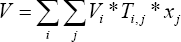

Where T is the coefficient matrix and the value of the element in the matrix equals to -1, 0 or 1. The subscript j corresponds to operation and subscript i correspond to part or subassembly. If operation j disassembles subassembly i, . If operation j assembles part i into a subassembly, . For other conditions, . For the example in Figure 11, the T matrix is as follows (Table 2):
Follow the same analysis for the disassembly operation cost, the complete disassembly LP model formulation is as follows:
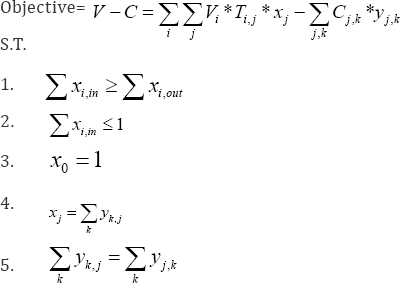
Decision variables are x j and y j, k and V i and are constant coefficients representing the value of each part/component and the cost of disassembly operation. All of the decision variables are binary variables.
Disassembly sequence generator application verification
This section verifies the Disassembly Sequence Generator application through an example (Figure 12). We start with the verification of the involved sub functions, which include:

a. loop detection,
b. Contact-Loop detection,
c. Contact-Loop Cluster detection and
d. Unconstrained Subassembly detection, in section 5.5.1. The overall procedure for generating all the feasible disassembly sequences is further validated in section 5.5.2. Lastly, in section 5.5.3, the LP-based optimization model is applied to the case study to find the optimal disassembly sequence Figure 12.
Sub function verification: Figure 13 shows the implementation of functions.

a. loop detection,
b. Contact-Loop detection,
c. Contact Loop Cluster detection and
d. unconstrained subassembly detection.
Applying those functions to the initial state of the product as shown in Figure 12. The following results are returned. There are 41 cycles in the current connection graph, among which five are identified as Contact-Loop:
L1:Part2->Part7->Part1 L2: Part2->Part8->Part3 L3: Part1->Part10->Part4
L4: Part1->Part6->Part5 L5: Part9->Part4->Part3
These Contact-Loops can be further clustered to form one Contact-LoopCluster:
“CLC1: Part2->Part7->Part1->Part8->Part3->Part10- >Part4->Part6->Part5->Part9”
There is no unconstrained subassembly at this state.
If the disassembly operator detaches Part7 and Part10, the EOL product reach a new state. The results of the above sub functions are (shown in Figure 14):
There are 17 cycles in the current connection graph, among which three are identified as Contact-Loop:

L1’: Part2->Part8->Part3 L2’: Part1->Part6->Part5 L3’: Part9->Part4->Part3
These Contact-Loops can be further clustered to form one Contact-LoopCluster:
“CLC1’: Part2->Part8->Part3->Part9->Part4”
Also, there is two unconstrained subassemblies at this state and they are:
L2’: Part1->Part6->Part5
CLC1’: Part2->Part8->Part3->Part9->Part4
From the results above, it is evident that the implemented sub functions return results as expected and we thus can verify the proposed sub functions.
Overall searching procedure verification: The overall procedure to generate all the feasible disassembly sequences has been shown in Figure 10. Here, we apply the case study problem to the application to demonstrate the search process. Figure 15 below shows the details of one search iteration, which generates one feasible disassembly sequence.
The application procedure starts with picking any of the Connecting Component as the candidate to be detached. In this example, Part9 is selected and the interference test is applied on it to check whether Part9 can be detached without collisions with the other components. The result from the interference test will be true, which indicates no collisions will happen during the disassembly of Part9. Next step is to check the component and subassembly level stability/disassembility. Because the product reaches a stable state (state 2) after the detachment of Part9 (there exists no unstable components or subassemblies), the detachment of Part9 is accepted as feasible disassembly step Figure 15.
At state 2, similar process will be applied. First, the application procedure will pick any of the Connecting Component as the candidate to be detached and Part10 is selected. Interference test will be further applied on Part10. However, in this state, even though Part10 can pass the interference test, it does not immediately accept the detachment of Part10 as a feasible disassembly process. It is because that the EOL product reached an unstable state (state 3) after Part10 is disassembled: the component level stability check will identify that component Part4 loses constraints along +x, -y, +z and -z directions and becomes unstable. Thus, further interference test on the unstable component Part4 should be carried out. In this case, Part4 can be detached and the EOL product will reach a stable state (State 4). Until this point, the application validates the feasibility of the disassembly process, "detachment of Part10” and disassembly process, "detachment of Part4”, and suggests they should be carried out sequentially in order to reach a stable state (State 4).

At state 4, similar process will be again applied and Part7 is selected as the candidate to be detached. The interference test on Part7 will be passed and the EOL product will reach state 5 if Part7 is detached. However, the EOL product in state 5 contains subassembly level instability: two unstrained subassemblies (S1: "Part1, Part5, Part6” and S2: "Part2, Part3, Part8”) are identified. Thus, the interference test will be applied to them and parallel disassembly will be applied to yield two stable subassemblies (State 6 and State 7). The searching process will iterate as above until all the feasible disassembly sequences are identified. The final result is shown in Figure 16.

The result as shown in Figure 16 identifies all the feasible can have theoretically 10! (3,628,800) disassembly sequences. disassembly sequences. We can see, with a 10 parts product, we However, the feasible disassembly sequences are much less (565 total for the case study problem) due to the geometrical and topological constraints. A further study on those generated feasible disassembly sequences shows that they are 100% feasible in real scenario, which means the application generate no error disassembly sequence, which is geometrically or topologically impractical.
LP-Based optimization model verification: The LP-based optimization model can be applied to generate an economically optimal disassembly sequence. Instead of applying the LP model directly on the AND/OR graph as shown in Figure 16, we pick a simpler example as shown in Figure 17 below to validate the LP optimization model, with the intension to be more concise and clear. Figure 17 represents a product with six parts (ABCDEF). All the feasible disassembly sequences are generated. Both total and partial disassembly is allowed as long as the profit is maximized.


The cost of disassembly operation is known, and has given in a matrix form (Figure 18); because, the cost of a certain disassembly operation is dependent on the previous operation. One single disassembly operation may cost differently depending on a particular disassembly sequence that has been previously followed till this operation. It means C1, 2 (cost of operation 2 carried out after operation 1) is different from C3, 2 (cost of operation 2 carried out after operation 3). Also the revenues of all the part, subassembly and assembly are known (Figure 18). They can be positive numbers which means they have some values for reuse or recycling; they can also be negative numbers which means they can't be reused or recycled and maybe hazardous to the environment: so they have negative values. Given this information, an optimal disassembly sequence needs to be determined so that the profit will be maximized.
Applying LP optimization model, the optimal path of the problem in Figure 17 is shown in Figure 19 below:?

In order to verify the model, the following two extreme cases are checked:
(1) Let us change the value of subassembly ABCD to extreme high. The program successfully stops at node ABCD for part reuse, as shown in Figure 20. It means that subassembly ABCD is valuable enough for reuse and it should not be further disassembled.
(2) Let us change the cost of disassembly operation C47 and C57 to very high values (big M). Because of the high operation costs associated to the operation 7, the optimal disassembly sequence will not continue through the arc 7 (which represents operation 7) and will detour to operation 8 instead, as shown in Figure 21.


From the analysis above, we can conclude that the optimization model is quite convincing and it generates optimal disassembly sequence as expected [24,25].
Conclusion and Future Work
This paper presents a Disassembly Planning Information Model, which constitutes a layered information framework designed for multiple applications in the domain of EOL product disassembly planning. DIM is hierarchically structured by layers, which divide the associated Information Models into different levels of abstraction, and thus, separate the general knowledge from the specific knowledge about particular domains and applications. A set of sub models is thus developed and classified into three different layers named the abstract level, the domain level and the application level. The developed DIM is applied to the disassembly sequencing problem to validate the usability and reusability performance regarding the DIM.
While this work has demonstrated the utilization potentials of applying the DIM in the domain of disassembly planning, many opportunities for extending the scope of this thesis remain. This includes: (1) promoting the DIM into a reference model, (2) applying more disassembly planning related applications to the DIM and (3) integrating DIM with current IoT infrastructure.
References
- Gungor A, Gupta Sm (1999) Issues in environmentally conscious manufacturing and product recovery: a survey. Computers & Industrial Engineering 36(4): 811-853.
- DONG J, ARNDT G (2003) A review of current research on disassembly sequence generation and computer aided design for disassembly. Proceedings of the Institution of Mechanical Engineers, Part B (Journal of Engineering Manufacture) 217: 299-312.
- Wang L, Wang XV, Gao L, Vancza J (2014) A cloud-based approach for WEEE remanufacturing. CIRP Annals - Manufacturing Technology 63(1): 409-412.
- Xia K, Gao L, Wang L, Li W (2015) A Semantic Information Services Framework for Sustainable WEEE Management Toward Cloud-Based Remanufacturing. Journal of manufacturing science and engineering 137(6).
- Penev KD, Penev KD, De Ron AJ, et al. (2002) Determination of a disassembly strategy. International Journal of Production Research 34(2): 495-506.
- Zhang HC, Kuo TC (1996) A graph-based approach to disassembly model for end-of-life product recycling. Electronics Manufacturing Technology Symposium, pp. 247-254.
- Murayama T, Oba F, Abe, S, Yamamichi Y (2001) Disassembly sequence generation using information entropy and heuristics for component replacement. Assembly and Task Planning, pp. 208-213.
- Kanai S, Sasaki R, Kishinami T (1999) Graph-based information modeling of product-process interactions for disassembly and recycle planning, Environmentally Conscious Design and Inverse Manufacturing, 1999. Proceedings. EcoDesign '99: First International Symposium On 1999, pp. 772-777.
- Zussman E, Mengchu Zhou, Caudill R (1998) Disassembly Petri net approach to modeling and planning disassembly processes of electronic products, Electronics and the Environment, 1998. ISEE- 1998. Proceedings of the 1998 IEEE International Symposium on 1998, pp. 331-336.
- Zussman E, Meng Chu Zhou (2000) Design and implementation of an adaptive process planner for disassembly processes. Robotics and Automation 16(2): pp. 171-179.
- Moore KE, Gungor A, Gupta SM (1998) A Petri net approach to disassembly process planning. Computers & Industrial Engineering 35(1-2): 165-168.
- Chevron D, Binder Z, Horacek P, Perret R (1997) Disassembling process modelling and operations planning under imprecise operation time, L: Systems Engineering and Management. Pergamon. pp. 367-72.
- Hsin-Hao H, Wang MH, Johnson MR (2000) Disassembly sequence generation using a neural network approach. Journal of Manufacturing Systems 19(2): 73-82.
- Lambert Ajd (1997) Optimal disassembly of complex products. International Journal of Production Research 35(9): 2509-2524.
- Lemaignan S, Siadat A, Dantan JY, Semenenko A (2006) MASON: A Proposal For An Ontology Of Manufacturing Domain. Distributed Intelligent Systems, pp. 195-200.
- Chang X (2008) Ontology Development and Utilization in Product Design, Virginia Polytechnic Institute and State University.
- Kumar Pavan k (2008) Design process modeling: Towards an ontology of engineering design activities, Clemson University. South Carolina
- Kim K, Manley DG, Yang H (2006) Ontology-based assembly design and information sharing for collaborative product development. Computer- Aided Design 38(12): 1233-1250.
- Foufou S, Fenves Sj, Bock C, Rachuri S, Sriram Rd (2005) A core product model for PLM with an illustrative XML implementation. Geneve, Switzerland: Inderscience Enterprises Limited, pp. 21-32.
- Baysal Mm, Roy U, Sudarsan R, Sriram Rd, Lyons Kw (2004) The open assembly model for the exchange of assembly and tolerance information: Overview and example, 2004 ASME Design Engineering Technical Conferences and Computers and Information in Engineering Conference, September 28, 2004 - October 2, 2004 2004, American Society of Mechanical Engineers, pp. 759-770.
- Feng Sc, Kramer T, Sriram Rd, Lee H, Joung Cb, et al. (2013) Disassembly process information model for remanufacturing. Journal of Computing and Information Science in Engineering, 13(3).
- Gruber TR (1995) Toward principles for the design of ontologies used for knowledge sharing? International Journal of Human-Computer Studies 43(5-6): 907-928.
- Zhu B (2016) An Information Model in the Domain of Disassembly Planning for Sustainable Manufacturing, Syracuse University.
- Galster M, Avgeriou P (2012) A Variability Viewpoint for Enterprise Software Systems, 2012 Joint Working IEEE/IFIP Conference on Software Architecture (WICSA 2012) & European Conference on Software Architecture (ECSA 2012), 20-24 Aug. 2012 2012, IEEE Computer Society, pp. 267-71.
- Gennari Jh, Musen Ma, Fergerson Rw, Grosso We, Crubezy M, et al. (2003) The evolution of Protege: An environment for knowledge-based systems development. International Journal of Human-Computer Studies 58(1): 89-123.


