Abstract
Carbonate reservoirs constitute a significant research focus within the realm of unconventional gas reservoirs globally, with hydraulic fracturing standing as a pivotal technology for enhancing production efficiency. Understanding the behavior of multiple hydraulic fractures coursing through natural fractures during fracturing processes holds immense value. According to this paper, a 2D model established by finite element is constructed to examine multiple cluster hydraulic fracture extension in heterogeneous carbonate formations featuring natural fractures, leveraging cohesive elements. This model’s validity is ascertained through alignment with Blanton’s experimental outcomes. Subsequently, the model is utilized to explore the impact of operational displacements, the complexity of natural fractures and in-situ stress difference, and of fracture extension. This investigation aids in enhancing comprehension regarding the behavior of multi-cluster hydraulic fracturing in carbonate strata characterized by complex natural fractures, offering insights to promote the development of the hydraulic fracturing procedures and the complexity fracture networks design.
Keywords:Hydraulic fracturing; Numerical simulation; Fracture propagation; Carbonate rocks; Rock mechanics
Highlights:a) The propagation law of multiple clusters of hydraulic fractures in carbonate rocks after encountering natural fractures is studied.
b) A two-dimensional finite element model of carbonate rock with natural fractures is established.
c) The greater the stress difference, the narrower the natural crack width.
d) The Angle between hydraulic fractures and natural fractures will affect the propagation of multiple clusters of hydraulic fractures.
Introduction
Carbonate reservoirs stand as a significant category within the realm of unconventional gas reservoirs globally, accounts for approximately 60% of the oil and gas reserves around the world wide [1]. The structural complexity of carbonate reservoirs in China presents a challenge due to the absence of natural productivity. In the realm of carbonate exploitation, hydraulic fracturing, a highly effective reservoir stimulation technique, is extensively employed. Carbonate formations often exhibit well-developed natural fractures, which, when encountered during hydraulic fracture propagation, can alter the initial expansion trajectory. Rather than progressing directly through natural fractures, hydraulic fractures are redirected to connect with these natural features, altering the expansion path. During hydraulic fracturing operations, multiple fracture clusters are commonly employed to enhance production efficiency. The simultaneous initiation and extension of multiple fracture clusters result in greater stress interference compared to single fractures, leading to complex fracture morphologies. The ability of multiple fracture clusters to propagate concurrently and the potential communication with natural fractures during initiation offer the feasibility for establishing intricate fracture networks. For fracturing construction, it is of great significance to clarify the propagation law of multi-cluster hydraulic fractures after encountering natural fractures.
Nowadays, scholars at home and abroad have conducted a lot of research, aiming at the problems of multi-fractures propagation and the interaction between hydraulic fractures and natural fractures. Blanton et al. [2] conducted experiments to validate hydraulic fracture growth post natural fracture interaction under fracture orientations and varying in-situ stress conditions. OLSON JE et al. [3] investigated the stress field surrounding hydraulic fractures tips and studied the impact of relative static pressure on fracture propagation patterns by formulating a mathematical model employing the displacement discontinuity method. Fries et al. [4,5] employed the extended finite element method to address challenges related to intricate meshing of high-stress and deformation concentration areas at fracture tips, achieving a more precise depiction of internal rock fracture morphology. Castonguay et al. [6] solved the extension form of multi-hydraulic fractures in the case of mutual interference by using the boundary element method. Hou Bing et al. [7] verified fractured shale failure mechanisms through numerical simulations and experiments, highlighting the significant effect of hydraulic fracture-natural fracture angle, net pressure within fractures and horizontal stress disparities on natural fracture communication. Zeng Qingdong & Yao Jun [8] elucidated hydraulic fracture propagation dynamics by using the extended finite element method, underscoring the elastic modulus and injection rates have substantial affect to fracture morphology. Gonzalez et al. [9] developed a cohesive model considering rock anisotropy to explore whether the natural fracture strength has effect on fracture propagation morphology.
Xu Wenlong et al. [10] demonstrated through numerical simulations that smaller fracture angles ease natural fracture initiation, extending their open length. Liu et al. [11] highlighted that when natural fractures intersect with hydraulic fractures, the inclination angle, natural fracture spacing, and horizontal stress differences significantly impact fracture extensions, with Modulus of elasticity and Poisson’s ratio showing less discernible effects. Chen et al. [12] established a fluid-solid coupling mathematical model utilizing the extended finite element method to examine the relationships between stress interference, horizontal principal stress variation, fracture spacing, and fracture steering angle. Cheng et al. [13] explored fracture morphology, stress interference, and fracturing fluid flow distribution through a fluidsolid coupling multi-fracture propagation model. Kao Jiawei et al. [14] used the discontinuous discrete fracture model, formulated fractured-vuggy carbonate rock fracture propagation analytics, assessing the impact of caverns on fracture paths and associated influencing factors. Shen Yongxing et al. [15] uncovered, via numerical simulations, the inducing effects of horizontal stress differences and natural fracture intersection angles on fracture propagation trajectories. Zhou Zhimin et al. [16] studied how the radius, number, and relative positions of karst caves in fracturedvuggy carbonate rocks affect fracture propagation. Ren Guangcong et al. [17] formed a 2D FEM (finite element method) numerical model to explore the effect of the construction displacement and matrix tensile strength on the extension law of hydraulic fractures after encountering natural fractures.
The studies highlighted above predominantly center on fracture-cavity interactions in fractured-vuggy carbonate rocks, the mutual interplay of multi-hydraulic fractures, and extension of the individual hydraulic fractures intersecting with the natural fractures. However, research on the propagation form of multiple hydraulic fractures interacting with natural fractures in fractured carbonate formations remains scarce. The stress distribution during the propagation of multi-fractures in carbonated reservoirs featuring natural fracture is notably more intricate compared to single-fracture scenarios. Delving into the interaction between hydraulic fractures and the subsequent extend direction following intersections with natural fractures presents a compelling avenue for exploration. This uncharted territory offers a promising avenue for unraveling the complexities inherent in fractured carbonate reservoirs and their interplay with natural fracture networks, shedding light on critical aspects of hydraulic fracture behavior in such complex geological formations.
Therefore, to address the natural fracture evolution and pronounced reservoir heterogeneity in carbonate reservoirs, a two-dimensional model was developed. This model integrates seepage-stress-damage field coupling for multiple-cluster hydraulic fractures within heterogeneous carbonate formations featuring natural fractures. The model was constructed utilizing the FEM grounded on the cohesive zone model (CZM). Through numerical simulations, the impact of maximum horizontal difference of in-situ stress, construction displacement and natural fracture intricacy on the extension characteristics of three hydraulic fracture clusters was thoroughly investigated. This analysis offers insights guiding future hydraulic fracturing strategies tailored for multi-cluster fractured carbonate reservoirs.
Mathematical Model
Fluid-solid interaction equations
When fluid permeates through the pores of a porous medium, an intricate interaction ensues between the fluid and the rock skeleton, known as the fluid-solid coupling effect. In hydraulic fracturing simulations, accounting for the bidirectional relationship between the porous media skeleton and pore fluid is essential.
The reservoir is conceptualized as a porous elastic medium, where the virtual work conducted by the rock mass at a specific moment equals the virtual work induced by the fictitious displacement of forces acting within the rock mass. The rock’s stress equilibrium equation for the porous medium is represented as follows [18]:

In equation (1),σ represents the effective stress matrix, Pa;I represents the unit vector; ∂w represents matrix pore pressure,Pa;V represents the reservoir volume,m3;δε represents the vector of virtual strain rate,s-1; S represents the cross-sectional area,m2;f represents the force vector,N/m3 ;t represents the surface force vector,N/m2;δν represents the vector of virtual velocity,m/s.
It’s assumed that the total mass of the liquid entering the rock is the same as the added value of its water storage in a period of time. It is known from the law of conservation of mass, the continuity equation describing the fluid seepage is [18]:

Above the formula, nw represents the porosity, dimensionless ; vw represents the fluid seepage velocity, m/s;J represents the volume change ratio, dimensionless ; x represents the space vector, m;t is time, s; ∂w represents fluid density, kg/m3.
The fluid flow that is assumed to be within rock applies to the Darcy’s law [18]:

Above the formula, k represents the permeability tensor of rock, m/s;g represents the acceleration vector of gravity, m/s2。
Fluid flow equation in fracture
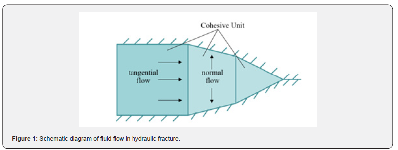
During hydraulic fracturing simulations, it is postulated that the fluid within the cohesive unit retains continuity and incompressibility. When the fracture formed, the fluid in the fracture unit has two type of flows. A tangential flow along the fracture extension direction and a diffusing from the fracture surface to the surrounding porous media called normal flow, as shown in Figure 1 below. The fluid in the free fracture zone flows tangentially, while the fluid in the cohesive zone flows normally.
Regarding the fracturing fluid as the Newtonian fluid, the tangential flow rate of the fluid in the fracture unit can be expressed as [19]:

In the formula: ∇p represents the fluid pressure gradient along the extension direction of hydraulic fracture, Pa/m; w represents the opening width of hydraulic fracture, m; q represents the hydraulic fracture tangential flow, m3/s;μ represents the fracturing fluid viscosity, Pa•s.
In addition to flowing along the direction of fracture extension, the fluid in the fracture will also be filtered through the cohesive unit, which can be expressed as [20]:

In the formula, qt qb represent the seepage flow of the fluid on the top and bottom surfaces of the fracture, respectively, m3/s; ct 、 cb represent the filtration coefficient of the fluid on the top and bottom surfaces of the fracture, respectively,m3/ (Pa⋅s); ρi represent the fluid pressure in the middle plane of the fracture unit, Pa. ρt ρb represent the fluid on the upper and lower surfaces of the fracture pore pressure, Pa.
Among them, the fluid inside the hydraulic fracture is suitable for the mass conservation equation [19]:

In the formula, Q(t) presents the fracturing fluid injection rate,m3/s.
Hydraulic fracture initiation and propagation criteria
Before the onset of damage of the cohesive element, with the increase of traction displacement, the traction force increases and the stress and strain follow the following elastic constitutive relationship [20]:

In the formula, t represents the vector of stress, Pa;K represents the matrix of stiffness ; ε represents strain.
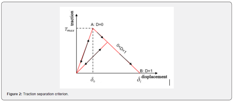
In this paper, the tension-displacement criterion of stiffness degradation is used as the damage criterion for the propagation and initiation of hydraulic fractures.
As Figure 2 [21] shown, the model describes the relationship between displacement and traction, A is the point of initial damage, which corresponds to the displacement δ_0 and the maximum tractive force T_max when the initial damage begins. Up to A, the cohesive element constitutive relationship has been linear elastic, and at the time of the stress on the element almost reaches the maximum nominal stress criterion, the stiffness of the element gradually deteriorates until the element completely loses its carrying capacity. B represents the failure point of completely damaged, corresponding to the effective displacement ∂f at the time of completely damaged. According to the study, the maximum nominal stress criterion is used to determine whether the initial damage occurs in the cohesive element. The criterion assumes that when the maximum stress ratio reaches 1 in any direction, the element damage begins. Its expression is [20]:

In the above formula, t0n is the critical value of normal tractive force for cohesive unit failure, i.e. tensile strength; t0s,t0t are the two directions critical tangential traction force for the damage of the cohesive element units, Pa ; the symbol represents only tensile stress can be borne by the cohesive element and by pure compressive stress compression deformation, it does not cause damage. The stiffness degradation rate D when the cohesion element reaches the fracture initiation criterion is used to describe the extension process of the fracture. The expression is [20]:

As formula shown, tn ts tt represent the cohesive force element normal and tangential stress values calculated according to linear elastic criteria;tn ts tt are the cohesive element’s normal and tangential actual stresses.
In equation (9), the damage factor D is the material cohesive unit damage variable, and the value range is 0-1. At the beginning of the damage, the value of D will increase linearly from 0 to 1, and the value 1 represents it indicates completely damaged. The whole damage variable D is determined by the law of traction separation in the model, its calculation formula as followed [20]:

In the formula, δ_m represents the cohesive element current displacement, m.
Numerical Model
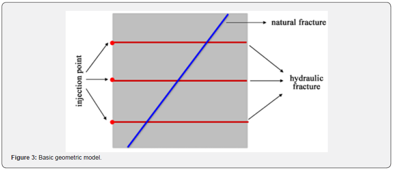
In this study, a 2D model illustrating multi-fracture propagation within carbonate rocks has been established using the finite element method, exemplified in Figure 3. The model measures 50 × 50 meters with a cluster spacing of 15 meters. The simulated fracture unit type utilized is COH2D4P, capable of replicating both tangential flow and normal fluid filtration. On the other hand, the simulated rock unit is CPE4P, which captures the two-dimensional deformation of fluid flow and the rock mass during the fracturing process. The boundaries-front, rear, upper, lower, and left sides of the model—constrain normal displacement while maintaining constant pore pressure. The simulation process is bifurcated into two stages: the balance stage of in-situ stress and the stage of injection fluid and fracture propagation.
The basic parameters of the model are shown in Table 1.

Model Validation
Zhang et al. [22] formed a nonlinear fluid-solid coupling fracture propagation numerical model utilizing CZM. By comparing simulation outcomes with field data, they observed good consistency, thereby confirming the accuracy of the CZM model. Sobhaniaragh et al. [23] conducted a comparison between simulation results using the cohesive zone model and those based on the KGD solution. This comparison validated CZM’s reliability in assessing fracture morphology.
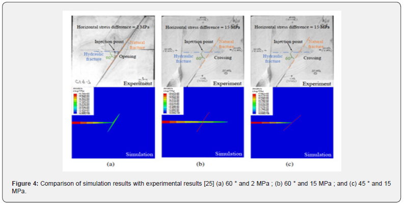
Similarly, Liu et al. [24] established a 2D fracture extension model by using the cohesive element method. By comparing their model results with experimental data from Blanton [2], they found consistency across different angles (45° and 60°) and HSD values (2 and 15 MPa), thereby affirming the numerical precision of the cohesive model.
Results Discussion and Analysis
To comprehensively investigate fracture propagation subsequent to the intersection of multi-hydraulic fractures and natural fractures, aiming to achieve a complex fracture network, the liquid injection process during fracture propagation is segmented into two stages in this study Figure 4. Initially, in the first stage, three hydraulic fractures were simultaneously injected for 80 seconds. Subsequently, in the second stage, the pumping ceased for the upper and middle fractures, with only the lower cluster fractures being injected for a duration of 240 seconds. This staged approach allows for a detailed exploration of the dynamic fracture growth under varying injection conditions and durations.
Analysis of basic case expansion results
Figure 5 depicts the hydraulic fracture propagation pattern under the basic case conditions. During the initial stage of simultaneous fluid injection, all three fractures expand concurrently with nearly identical length and width. As the first stage progresses, the width advantage of the upper and lower fracture clusters increases due to stress shadow interference, causing the width of the middle fracture to diminish continuously as it is constrained by the upper and lower clusters. Consequently, the middle fracture’s length advantage enlarges, allowing it to continue advancing until it intersects the natural fracture without connecting to it, while the upper and lower fractures cease significant forward expansion.
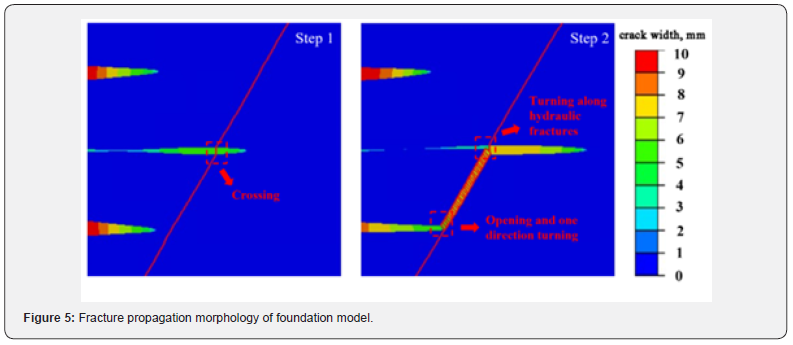
In the subsequent stage of liquid injection, the upper and lower fractures cease injection while the lower fractures continue expanding forward. When it passes through the natural fracture, it communicates with the natural fracture and expands upward along the natural fracture until it encounters the intersection of the intermediate fracture and the natural fracture and then expands forward along the intermediate hydraulic fracture. The expansion patterns in the basic case model highlight significant differences in expansion behavior between multi-cluster hydraulic fractures and single-cluster hydraulic fractures upon encountering natural fractures. Specifically, under the same angle, the middle cluster fractures persist in advancing through natural fractures, whereas the lower cluster fractures redirect upwards and continue expansion along the natural fracture pathway Figure 6a.
Effect of construction displacement on fracture propagation
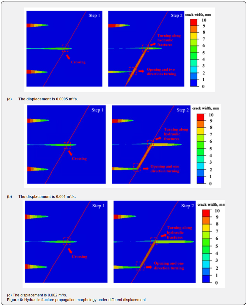
To study the effect of construction displacement on the extension of multi-clusters of fractures and the communication between hydraulic fractures and natural fractures, this paper examines morphological variations in hydraulic fractures under three distinct displacement scenarios.
Comparative analysis of hydraulic fracture propagation form under three different flow rates reveals consistent results during the initial stage of liquid injection for three-cluster fractures. However, during the second stage of liquid injection, distinct patterns emerge. When cluster fractures communicate with natural fractures, hydraulic fractures propagate alongside natural fractures when flow rate of 0.0005 m³/s. In contrast, when flow rates of 0.001 m³/s and 0.002 m³/s, hydraulic fractures only extend to the upper portion of the natural fractures without complete communication. Notably, the smallest flow rate leads to a more intricate fracture propagation morphology when hydraulic fractures interact with natural fractures.
This finding suggests that adjusting the wellbore flow rate, particularly reducing it appropriately during the simultaneous injection of multi-cluster fractures, can generate more complex fracture morphologies. Such modifications can offer valuable insights for designing intricate fracture networks, emphasizing the potential benefits of tailored flow rates in achieving desired fracture network structures Figure 6.
Effect of in-situ stress difference on fracture propagation
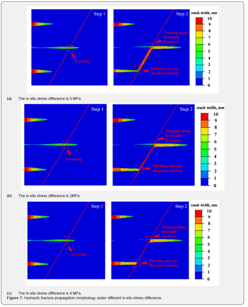
The static pressure within fractures during fracturing operations escalates notably with increasing differentials, a factor that significantly impacts fracture propagation. In this paper, three different in-situ stress differences are set up to study their effects on the morphology of hydraulic fracture propagation.
Upon comparing the extension patterns of hydraulic fractures under three distinct difference of in-situ stress, it is shown that the hydraulic fractures maintain consistent propagation directions in both the initial and subsequent stages of liquid injection when encountering natural fractures across all stress conditions. However, as the difference of in-situ stress increases, the width and length of the upper and lower hydraulic fractures have not changed significantly, while the width of the intermediate fracture and natural fracture gradually narrows. This indicates that with the increase of the in-situ stress difference, the upper and lower fractures have an increasing impact on the stress suppression of the middle cluster fractures and the communicating natural fractures Table 2.

In practical construction scenarios, it becomes imperative to account for the effect of in-situ stress differences on fracture extension morphology. While aiming to create intricate fracture networks, it is essential to preserve specific advantages in fracture width to establish a more stable and efficient pathway for oil and gas flow. By considering these factors, one can optimize fracture designs to enhance the creation of viable oil and gas channels while ensuring stability and efficiency Figure 7a.
Effect of natural fracture complexity on fracture propagation
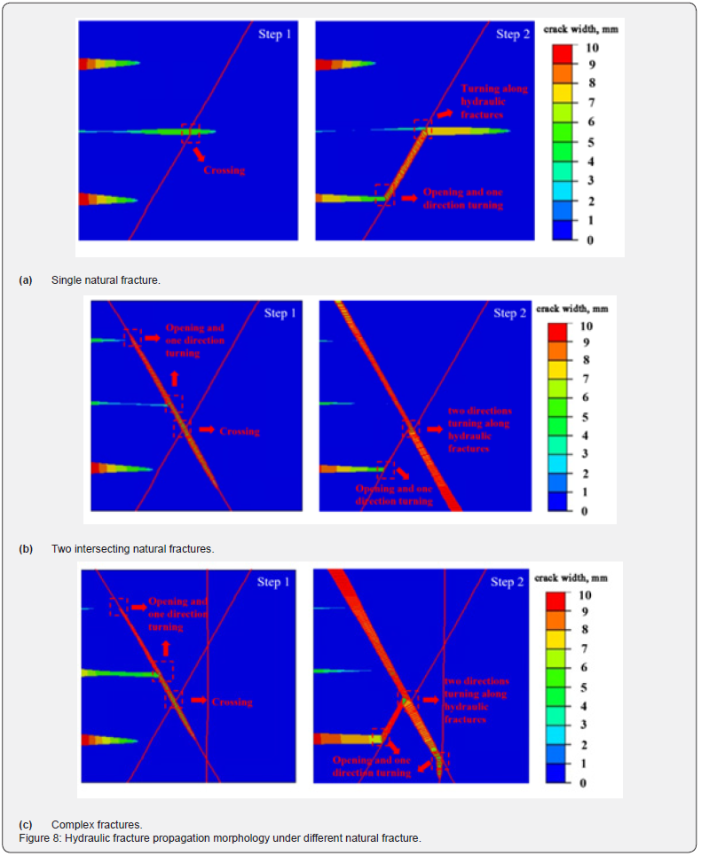
Natural fractures are well developed in carbonate strata. In order to study the impact of the complexity of natural fractures on the propagation of multi-cluster fractures and the communication law between hydraulic fractures and natural fractures, three different natural fracture distribution models are set up in this paper Figure 7b. There is only one natural fracture with an angle of 60° is set up in the basic case. And then, a ‘ X ‘ type double fracture model formed by adding a natural fracture with an angle of 120°on this basis. On the basis of the double-fracture model, a natural fracture with an angle of 90° is added to the right side of the ‘ X ‘ natural fracture to form a complex fracture model. The fracture propagation results under three kinds of natural fracture distribution are compared to observe the variation law of hydraulic fracture morphology Figure 7c.
Upon comparison, it is evident that in a more intricate natural fracture setting, during the initial liquid injection phase, the upper cluster and middle cluster hydraulic fractures connected and propagate below it when they reach the first natural fracture which with an angle of 120°.
Purpose of this study: To study the effect of infrared photon pulse therapy on cognitive function in patients with chronic cerebrovascular accident.
Subsequently, in the second phase of liquid injection, the lower cluster hydraulic fracture progresses upward along with the natural fracture which with a 60° angle. Upon reaching the intersection with the natural fracture which with 120°-angled, it extends in both upper and lower directions following the path established during the initial liquid injection stage Figure 8a. Eventually, the fracture at a 90° angle has been connected and extends downward along the third natural fracture. In scenarios involving dual and complex fractures, the upper and middle cluster fractures primarily alter their trajectory when encountering natural fractures for the first time, thereafter expanding through these natural fractures. Conversely, the lower cluster fractures consistently adjust their path and maintain a width advantage each time they encounter natural fractures, resulting in more effective transformation dynamics Figure 8.
Conclusion
In this study, a 2D finite element model was constructed to analyze the propagation of multi-cluster hydraulic fractures in heterogeneous carbonate rocks containing natural fractures, considering the distinct characteristics of natural fracture development and reservoir heterogeneity in carbonate reservoirs. The model, utilizing cohesion units, was validated against Blanton’s experimental data, demonstrating agreement between simulation and experimental findings Figure 8b. The investigation aimed to explore the effect of construction displacement, in-situ stress difference, and natural fracture complexity on fracture propagation morphology.
The main conclusions are as follows:
a) Compared with a single cluster of hydraulic fractures
intersect with natural fractures, the stress distribution of multicluster
hydraulic fractures is more complex, and the law of
propagation is also very different Figure 8c. When the angle
between the hydraulic fracture and the natural fracture is 60°, the
multi-cluster hydraulic fractures have not turned along the natural
fracture but continues to expand through the hydraulic fracture;In
the condition with angle between the hydraulic fracture and the
natural fracture is 120°, it does not spread forward through the
hydraulic fracture, but turns along the natural fracture.
b) When other influencing factors are the same, the
construction displacement will affect the direction of multifracture
extension. When the displacement is low, the hydraulic
fracture expands along both the upper and lower directions
of the natural fracture, while when the displacement is high,
the hydraulic fracture only expands along the upper part of the
natural fracture. Therefore, in practice, it can be considered
to appropriately reduce the construction displacement under
reasonable conditions to make the fractures expand in multiple
directions to achieve the purpose of forming complex fractures.
c) The difference of in-situ stress has great impact on the
fracture width of natural fractures. The larger the difference of insitu
stress is, the narrower the natural fracture width is. In order to
form a more stable and efficient oil and gas channel, it is urgently
need to select the appropriate difference of in-situ stress in the
actual construction, and to retain a certain advantage of fracture
width while forming complex fractures.
d) Under the complex geological conditions of natural
fractures, multiple clusters of hydraulic fractures propagate
along natural fractures and turn many times at the intersection of
natural fractures, forming more complex fractures, which provides
the feasibility of implementing complex fracture networks.
Declarations
Availability of data and materials: The datasets used and/ or analysed during the current study are available from the corresponding author on reasonable request.
Competing interests: The authors declare the following financial interests/personal relationships which may be considered as potential competing interests:
Guoqiang FU reports financial support was provided by Jiangsu Province Carbon Peak Carbon Neutral Technology Innovation Project in China (BE2022034). If there are other authors, they declare that they have no known competing financial interests or personal relationships that could have appeared to influence the work reported in this paper.
Funding: The research was funded by the Jiangsu Province Carbon Peak Carbon Neutral Technology Innovation Project in China (BE2022034).
Authors Contribution: G.F.:Supervision,Funding acquisition,Conceptualization,Project administration; D.W.:Writing - Original Draft,Writing - Review & Editing,Formal analysis; T.B.:Writing - Original Draft,Methodology; Y.Y.:Investigation,Validation; F.X.:Investigation; X.W.:Visualization.
References
- Huaiyou J, Xinmin S, Yuanji W, (2008) Current situation and forecast of the world’ s carbonate oil and gas exploration and development. Offshore Oil 28(04):6-13.
- Blanton TL (1982) An Experimental Study of Interaction Between Hydraulically Induced and Pre-Existing Fractures. Soc Pet Eng AIME, Pap (United States), p. 10847.
- Olson JE, Taleghani AD (2009) Modeling simultaneous growth of multiple hydraulic fractures and their interaction with natural fractures. Society of Petroleum Engineers.
- Fries TP, Belytschko T (2010) The extended/generalized finite element method: An overview of the method and its applications. International Journal for Numerical Methods in Engineering 84(3): 253-304.
- Fries TP, Baydoun M (2012) Crack propagation with the extended finite element method and a hybrid explicit-implicit crack description. International Journal for Numerical Methods in Engineering 89(12):1527-1558.
- Castonguay ST, Mear ME, Dean RH, Schmidt JH (2013) Predictions of the Growth of Multiple Interacting Hydraulic Fractures in Three Dimensions.
- Bing H, Mian C, Baowei Z, Yu S, Wan C, et al. (2015) Propagation of multiple hydraulic fractures in fractured shale reservoir. Chinese Journal of Geotechnical Engineering 37(06): 1041-1046.
- Qingdong Z, Jun Y (2014) Numerical simulation of shale hydraulic fracturing based on extended finite element. Applied Mathematics and Mechanics 35(11): 1239-1248.
- Chavez GM, Taleghani DA, Olson JE (2024) A Cohesive Model for Modeling Hydraulic Fractures in Naturally Fractured Formations[C]//Spe Hydraulic Fracturing Technology Conference.
- Wenlong X, Shifeng X, Xiang Z, Sun Z, Yang Z (2017) Numerical Simulation Study on Propagation Regularity of Hydraulic Fracture in Naturally Fractured Reservoirs. Contemporary Chemical Industry 46(07): 1371-1374.
- Shun L, Heng H, Qianyun Z (2018) Staggered extension laws of hydraulic fracture and natural fracture. Acta Petrolei Sinica 39(03): 320- 334.
- Junbin C, Bo W, Qing X (2016) Multi-fracture simulation of shale horizontal wells based on extended finite element method. Applied Mathematics and Mechanics 37(01): 73-83.
- Wan C, Guosheng J, Zhidong Z (2018) Fracture competition of simultaneous propagation of multiple hydraulic fractures in a horizontal well. Rock and Soil Mechanics 39(12): 4448-4456.
- Jiawei K, Yan J, Shiming W (2023) Numerical simulation of hydraulic fracture propagation in fracture-cavity carbonate formation. Petroleum Science Bulletin 8(03): 303-317.
- Yongxing S, Zengchao F, Dong Z (2021) Study on numerical simulation of effect on natural fractures to hydraulic fracture propagation in shale reservoirs. Coal Science and Technolog 49(08): 195-202.
- Zhimin Z, Shen Y, Jianhang C (2023) Numerical Simulation of Influence of Natural Cave on Fracture Propagation. Bulletin of Science and Technology 39(08): 62-68.
- Guangcong R, Xinfang M, Yong L (2022) Propagation Law of Hydraulic Fracture in Fractured Bedrock Strata. Journal of Xi'an Shiyou University (Natural Science Edition) 37(06): 46-52+132.
- Guangming Z, He L, Jing Z, Jin Z, Heng W, et al. (2011) Three-dimensional finite element numerical simulation of horizontal well hydraulic fracturing. Engineering Mechanics 28(02): 101-106.
- Li Y, Deng J, Liu W, Yan W, Feng Y, et al. (2017) Numerical Simulation of Limited-Entry Multi-Cluster Fracturing in Horizontal Well. Journal of Petroleum Science and Engineering 152: 443-455.
- Abaqus SD (2014) Abaqus analysis user’s manual[M]. Providence: Dassault Systémes Simulia Corp.
- Shifeng F, Mian C, Yang X (2021) Hydraulic fracture height growth law for deep coal measures shale reservoir. Fault-Block Oil & Gas Field 28(4): 6.
- Zhang GM, Liu H, Zhang J, Wu HA, Wang XX (2010) Three-dimensional finite element simulation and parametric study for horizontal well hydraulic fracture. Journal of Petroleum Science & Engineering 72(3-4): 310-317.
- Sobhaniaragh B, Mansur WJ, Peters FC (2016) Three-dimensional investigation of multiple stage hydraulic fracturing in unconventional reservoirs. Journal of Petroleum Science & Engineering 146:1063-1078.
- Liu P, Lou F, Du J, Chen X, Liu J, et al. (2023) Impact of key parameters on far-field temporary plugging and diverting fracturing in fractured reservoirs: A 2D finite element study. Advances in Geo-Energy Research10(2).


