


A Novel Scheme of Three to Eleven Phases Transformer Connection by using MATLAB Software
*Satish Karekar
Department of Electrical Engineering, Chhattisgarh Swami Vivekan and Technical University, India
Submission: January 08, 2018; Published: January 25, 2018
*Corresponding author: Satish Karekar, Department of Electrical Engineering, Chhattisgarh Swami Vivekanand Technical University, India, Email: satishkarekar67@gmail.com
How to cite this article: Satish Karekar. A Novel Scheme of Three to Eleven Phases Transformer Connection by using MATLAB Software. JOJ Material Sci. 2018; 4(1): 555627. DOI: 10.19080/JOJMS.2018.04.555627
Abstract
A novel scheme of three to eleven AC multiphase transformer to convert into DC power through modeling. The whole modeling has been simulated by using MATLAB Software. Multi-winding transformer block was taken from the sim-power system block library and turn ratios set in the dialog box then simulated. The complete design and simulation of the proposed work is presented in this paper. Now we have mentioned the simulation results only for RL load. Eleven phase transmission system can be developed for the generation of bulk power transfer. As per need of the induction motor under a loaded condition is used to proof the viability of transformation system. In eleven phase's, each phases shifted from the order by 32.73° (360°/11) and got the sin wave voltage/current. The connection scheme was expanded by using the modeling and simulation approach to prove the viability of the implementation.
Keywords: Multi-winding transformer; Multiphase system; Multiphase transmission; Three-to-Eleven phases
Introduction
A transformer is a static device that transfers electric power from one circuit to another without a change of frequency. The physical basis of a transformer is mutual induction between two circuits linked by a common magnetic flux. It is often used to raise or lower voltage and also for impedance transformation [1]. The transformer is an important element in the development of high-voltage electric power transmission. Transformers can be classified into various types (step up, step down and matching transformers) according to ratio of the numbers of turns in the coils (turns ratio), as well as whether or not the primary and secondary are isolated [2].
Multiphase i.e. More than three phase systems are the focus on research recently due to their inherent advantage compared to the three phase counterparts. It has applicability of explored to electric power generation in multiphase systems [3-5] transmission [4-6] and utilization [7,8]. The research on eleven-phase transmission system was initiated due to the increasing a rising cost of right way for a transmission corridors, environmental program, and various stringent licensing laws [9]. Six-phase transmission lines can provide the same power capacity with a lower line voltage and smaller towers as compared to a standard double circuit three-phase line [4]. The dimension of the six-phase smaller towers may also lead to the reduction of magnetic fields and electromagnetic interference [9,10]. Normally no-load test, blocked rotor and load tests are performed on a motor to determine its parameters. Although the supply is used for multiphase motor drives obtained from multiphase inverters could have more current ripples, these are the controlling methods available to lower the current distortion below 1%, based on application and requirement [11-15]. We know that from the theory multi-phase motors are invariably supplied by ac/dc/ac converters. Thus, the multiphase electric drive is limited for the modeling and control of the supply systems [15]. Our main work is to develop statictrans formation system to change the phase number from three to eleven-phase (where n>3 and odd). Now we, are generating a novel phase transformation system which convert three phase to an eleven- phase supply [16].
In Multiphase, system six phase and twelve phase is found to produce less ripple with a high frequency in an AC-DC rectifier system. Thus six and twelve phase transformers are designed to feed a number of pulses rectifier system and technology has matured [17]. Recently, twenty four phase and thirty six phase transformer systems have proposed for supplying a number of pulse rectifier systems [14-18]. These designs are also available for an odd number of phases, such as five, nine and eleven etc. In this paper we have proposed a special transformer connection scheme to get a balance eleven-phase output supply from the balance three-phase input supply [19-21]. The expected application areas of the power transformer are the electric power transmission system and power electronic converters (AC-DC and AC-AC), and the multiphase electric drive system. The block represented of the proposed system is shown in Figure 1. The fixed voltage and fixed frequency available grid supply can be transformed to the fixed frequency Eleven-phase output supply. The output however, may be made variable by inserting the autotransformer at the primary side. The input and output supply can be arranged in the following manner [22] as below.

a) Input Star, Output Star
b) Input Star, Output hendecagon.
c) Input Delta, Output Star.
d) Input Delta, Output hendecagon.
The input has being three-phase system the windings are connected in a usually fashion. The hendecagon output connection may be derived following a similar approach. The output/secondary side connection is discussed in the following subsections.
Winding Arrangement of Eleven Phase Star Output
Here separates iron core are designated with one primary and three secondary coils, six terminal of primary side are connected in an adoptable manner resulting in star and or delta connection and the 26 terminals of secondary's are connected in a different fashion in a star/hendecagon output. The new connection scheme of secondary winding to obtain an input star and output star is illustrated in Figures 2 and the corresponding phasor diagram is shown in Figure 3 similarly for input delta and output star connection is also shown in the Figure 4. The construction of the output (star) phase with requisite phase angles of 360/11=32.73° between each phase is obtained using appropriate turn ratio and the governing phasor equation is given in Figure 5. Selecting the turn ratio is the key in creating the phase displacement in the output phases. The turn ratio between different phases is given in the Table 1. The input phases are made and is given with letter is "x", ”y” and "z" and output are designed with letter is "a", "b", "c", "d", "e", "f", "g", "h", "i", "j", and "k". The mathematically derivation for this connection is the basic addition of real and imaginary part of vectors. Given example, to the solution (1) gives the turn ratio of the phase "b", (Vb taken as unity).


(*MWT=Multi-winding transformer)


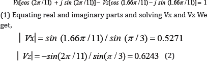
Thus Figure 5 is the result voltage of the two different coils; one output phase is generated from only one coil namely �ga3a4�h in contrast to another phase utilizes by two coils.
Winding Arrangement of Eleven Phase Delta Output
In this case winding arrangement three separate cores designed with individual carrying primary and two secondary coils. In this designed the phase difference will be 32.73. Six terminals of primaries are connected in an appropriate manner resulting in delta-hendecagon. Simulation, twenty six terminals of secondary are connected in star-hendecagon output. The turn ratios are different in an individual phase. The input phases are designed given with letters "x”, "y”, and "z” and the output are designated with letters are "A”, "B”, "C”, "D”, "E”, "F”, "G”, "H”, "I”, "J”, and "K”. The three phases to eleven phase connection designed model is shown in Figures 6-8 in this value of Va=Vx.


(*MWT = Multi-winding transformer)

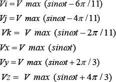
When there is a three-phase voltages (line-to-neutral) are defined as.
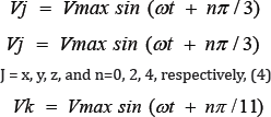
k=1,2,3,4,5,6,7,8,9,10,11and n=0,2,4,6,8,10,12,14,16,18,20 respectively (5)
Using Figure 5, an eleven -phase output can be created from a three phase input supply. A transformer is a two-port network the opposite connection is also possible that is if eleven-phase supply is given at the input the output can be three phase. It is very important if the power generated is eleven phases it has to be converted to three phase which has to be connected to the grid (Figure 9).

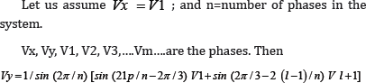
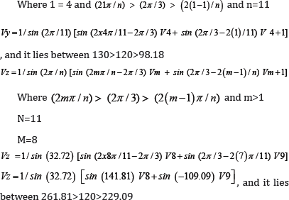
A general expression for "n" phase system derived as.
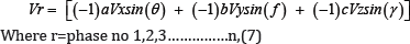
From the above Figure 10 we can derive an expression for a general case,

Simulation Results
The new designed/structure is at the first using "Sim power system" block set of the MATLAB/Simulink sofware. Multiwinding transformer block is chosen from the sim-power system block library and the turn ratios are set in the dialog box and the simulation is run. The resulting input and output current and votage waveform are given in Figures 11-13 and Figures 12-16 for star-star and Figures 17 & 18 and Figure 19 & 20 for delta-star. The output will be unbalance if input is unbalanced and also if the input is balance then output is also balance. The three phase output from a eleven phase input supply can also be obtain in similar fasion [22-30].


Results and Discussion
In this experimental setup and their simulation results obtained by using the designed three to eleven phase transformation system. The novel designed transformation system ratio are 1:1 (input: output), then the output voltage is similar to the input voltage. Now transformation ratio can be alterd to suit the step up or step down requirements. In this simulation we have No-load and load tests are performed on the three to eleven phase transformers and their load test are performed by connecting eleven phase RL load. The value of load is given by R=50H and L=5mH. Thus the (star-star) connection resulting waveforms of a three phase primary side and an eleven phase secondary side are shown in Figures 12 & 14 respectively. When three single phase autotransformers are used to supply input phases of the transformer connections. The output voltage can also be adjusted by simply varying the taps of the autotransformer. The output voltage is balance then input voltage is also balance. Any unbalancing in the input is directly reflected in the output phases. Under no-load conditions, 440 V is applied at the primary side. The input side voltage and current waveforms, under no-load and loaded steady-state conditions, the input voltage and currents under loaded conditions are 440 V and 24 A are recorded and shown in Figure 12. Corresponding no-load and loaded condition voltage and current waveforms for the secondary side (eleven phase) and the loaded current in the secondary side is nearly 14 A and the voltage is 400 V are presented in the Figure 15.
Conclusion
This paper proposes a new complex transformer connection scheme to transform three phase grid power to an Eleven-phase output supply. The new connection scheme and the phasor diagram along with the turn ratios are illustrated. This method required the main data of transformer, the phase shifting and as well as the winding connections of the transformer. The Eleven- phase induction motor under a loaded condition is used to prove the viability of the transformation system. The 3/11 AC multiphase transformer has been simulated by using MATLAB simulation software, which has been proved to be powerful tools to simulates such a typical connection transformers.
References
- Satish Karekar (2016) A Possibilities of Simulation of Three Phases to Thirteen Phase's Transformer Connection. IJRASET International Journal for Research in Applied Science & Engineering Technology 4(IV): 884-893.
- Satish Karekar (2016) Modelling and Simulation of Three phases to Seven phases Transformer Connecttion. IJRASET International Journal for Research in Applied Science & Engineering Technology 4(IV): 273280
- Hoteit Ahmad and Hamidovich Gaitov (2012) AC/DC Power Conversion System Using 3/9 Multiphase Transformer. IJCSI International Journal of Computer Science Issues 9(4): 68-70.
- Furmanczyk F, Stefanich M (2004) Demonstration of very high power airborne AC to DC converter. Power systems conference Reno pp. 200201- 3210.
- Basic D, Zhu JG, Boardman G (2003) Transient performance study of brushless doubly fed twin stator generator. IEEE Trans Power Convers 18(3): 400-408.
- Stewart JR, Kallaur E, Grant J (1984) Economics of EHV high/Phase order Transmission. IEEE Tras Power App System 103(11): 3386-3392.
- Singh GK (2008) Modelling and experimental analysis of a self excited six-phase induction generator for stand alone renewable energy generation. Renewable Energy 33(7): 1605-1612.
- Landes TL, Richeda RJ, Kriszanskas E, Stewart JR, Brown RA (1998) High phase order economic: Constructing a new transmission line. IEEE Trans Power Del 13(4): 1521-1526.
- Abbas MA, Chirsten R, jahns TM (1984) Six- phase voltage source inverter driven induction motor. IEEE Trans Ind Appl IA-20(5): 12511259.?
- Jones M, Levi E (2002) A literature survey of the state-of -the-art in multiphase drives. In proc Int UPEC Stafford UK pp. 505-510.
- Iqbal A, Moinuddin S, Khan, MR, Ahmed SK M and Abu-Rub H (2012) A novel three-phase toseven-phase transformation using special transformer connection. IEEE Trans Energy Conversion 27(3): 757766.
- Stewart JR, Wilson DD (1978) High phase order transmission-a feasibility analysis Part-1-Steady state considerations. IEEE Trans Power App System 97(6): 2300-2307.
- Dujic D, M Jones, E levi (2009) Analysis of output current ripple rmsin multiphase anddrives using space vector approach. IEEE Trans Power Elect 24(8): 1926-1938.
- Choi S, Lee BS, Enjeti PN (1997) New 24-pulse diode rectifier systems for utility interfaceof high power AC motor drives. IEEE Trans Ind Appl 33(2): 531-541.
- Srinivas goud L, Srivani T (2013) A Simulation of three phase to multiphase transformationusing a special transformer. International Journal of Science and Research (IJSR) 2(7): 351-357.
- Iqbal A (2005) Modelling and control of series-connection Five-phase and six phase two-motordrives. Phd dissertation school Eng Liverpool John Moores Univ school eng Liverpool, UK.
- Tewari SN, Singh GK, Saroor AB (1992) Multiphase power transmission research-Asurvey, Electr. Power System Res 24(3): 207-215.
- Singh B, Gairola S (2008) A 24 pulse AC-DC converter emplying a pulse doubling techniquefor vector controlled industries motor drives. IETE J Res 54(4): 314-322.
- Iqbal A, Moinuddin S, Khan MR, Ahmed SK M, Abu-Rub H (2012) A novel three-phaseto seven-phase transformation using special transformer connection. IEEE Trans Energy Conversion 27(3): 757-766.
- Iqbal A (2005) Modelling and control of series-connection Five-phase and six phase two-motordrives. Phd dissertation school Eng Liverpool John Moores Univ school eng Liverpool UK.
- Levi E (2008) Multiphase electric machine for the varable- speed application. IEEE Trans Ind Electron 55(5): 1893-909.
- Somashekar B, Chandrasekhar B, D Livingston David (2013) Modelling and Simulation ofthree to nine phase using special transformer connection. IJETAE 3: 630-638.
- Abbas MA, Chirsten R, jahns TM (1984) Six - phase voltage source inverter driven induction motor. IEEE Trans Ind Appl IA-20(5): 12511259.
- Bojoi R, Farina F, Profumo F, Tenconi A (2006) Dual-Three phase induction machine drives control- A survey. Inst Elect Eng Jpn Trans Ind Appl 126(4): 420-429.
- Ward EE and Harer H (1969) Preliminary investigation of an inverter - fed 5 phase induction motor. proc Inst Elect Eng 1166(6).
- Portela CM, Tavares MC (1993) Six-phase transmission line- propogation characteristics andnew three-phase representation. IEEE Trans Power Del 18(3): 1470-1483.
- Arahal MR, Duran MJ (2009). Pi tuning of five-phase drives with third harmonicinjection. Control Eng Practical 17: 787-797.
- Duran MJ, Salas F, Arahal MR, (2008) Bifurcation analysis of five-phase induction motordrives with third harmonic injection. IEEE Trans Ind Electron 55(5): 2006-2014.
- Ojo O, Dong G (2005) Generalized discontinuous carrier-based PWD modulation schme formulti-phase converter-machine system. Presnted at the IEEE Ind Appl Soc Annu Meet IAS (CD-ROM Pp no. 38P3) Hong Kong China.
- Ojo O, Davidson, I E (2000) PWM-VSI inverter- assisted stand-alone dual ststor windinginduction generator. IEEE Trans Ind Appl 36(6): 1604-1611.


