Concept Design of Airplane Structures
Bandyopadhyay N*
Consulting Engineer, India
Submission: April 17, 2017; Published: May 05, 2017
*Corresponding author: Bandyopadhyay N, Consulting Engineer, Kolkata, India, Tel: 91-33-2452-6436; Email: nbandyopadhyay@hotmail.com
How to cite this article: Bandyopadhyay N. Concept Design of Airplane Structures. JOJ Material Sci. 2017; 1(3): 555562. DOI:10.19080/JOJMS.2017.01.555563
Short Communication
During my professional career spanning over four decades handling variety of projects from designs (FEED) to project completion in various countries which involved design of variety of structures in accordance with various international codes and standards, I have used my experience in writing this paper Though Aeronautical Engineering is not my field of specialization but I have used my basic knowledge in complicated structural designs to develop this concept design of Aircraft structures manually. Current design practice using various soft ware programs gives more accurate and economical designs and more reliability. But this requires in-depth knowledge and training in using these software's. Manual designs as outlined here are simple, do not require costly training and can be handled by less experienced engineers. To ensure high degree of safety and reliability, the designs prepared manually can be checked though soft ware programs. This is thus a Research paper and can be considered for publication (Figure 1-3).

Design Procedure (Floating Mass Balance)
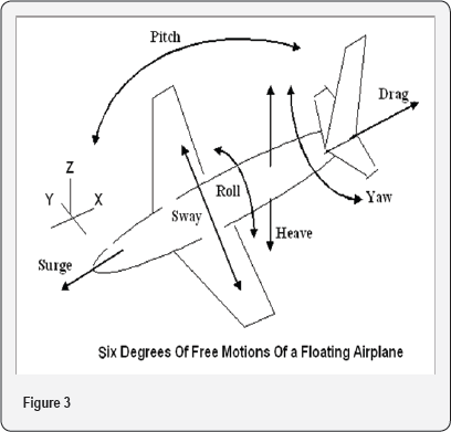
A flying aircraft is a floating body having six degrees of free movement namely three in linear directions and three in rotational directions. The freedoms in linear directions are Surge and Drag along the body (Fuselage) of the aircraft (X-axis), Sway across the fuselage at right angles to Surge (Y-axis) and Heave vertically on the Fuselage (Z-axis).
The rotational freedoms are termed as Pitch across the Y-axis, Roll across the X-axis and Yaw across the Z-axis. These six degrees of freedom are shown in the above sketch.
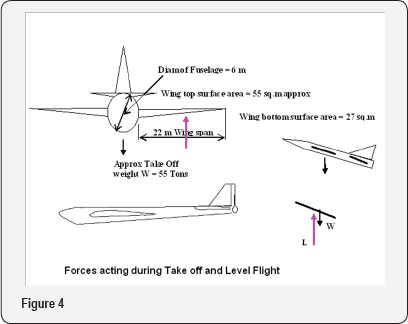
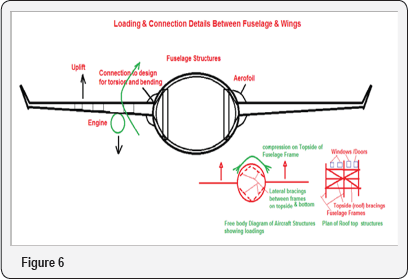
In addition to the dead load of the aircraft from its own weight, weight of passengers and cargo, fuel and other miscellaneous loads which is constant while on ground or during flight , the other six motions result from the action of wind while taking off, during flight and during landing. The main body or Fuselage of the plane must withstand all the loads and maintain the overall structural, integrity with high degree of safety and reliability while the other components of the plane control the effects of the loads resulting from the six degrees of motion. Thus, we can say that the Fuselage is like a main beam taking all loads from other parts to guarantee fail safe operation over many years. This beam ultimately takes loads in six planes and directions and therefore, must have guaranteed strength and rigidity in any axis and plane. From our basic knowledge we can say for certain that a circular beam section has equal strength and rigidity in any plane and direction. Thus, we can say that the ideal cross section of the fuselage should be near circular to the extent possible. From operational point of view the inside must be hollow to accommodate passengers, cargoes and machinery We will analyse the case of an aircraft, assuming the following dimensions. This will provide necessary guidelines for designing an actual aircraft (Figure 4-6).
Design Calculations
Aircraft take off speed=400km/hr=110m/s. Corresponding wind speed=105m/s considering some reduction due to skin friction. Wind pressure on the wings at this speed=0.6 x 1052=6615N/m2=0.662T/m2
Take off load, 80 passengers @ 80kg/pgr =6.4 say 7T, Aircraft DW including fuel =48T?
Total take off load=55 T
Difference in wing areas subject to wind uplift =27x2=54m2
Difference in Fuselage top and bottom surfaces approx =0.6x π x 7=13.9 say 14m2
Total area of the aircraft subject to wind uplift at take off =68m2
Assumed Angle of Attack of the aircraft at take off =20°
Therefore component of vertical downward load at right angles to wind =55 x Sin 20°=55x0.34 =18.8 T say 20T
Max uplift force on the wings and fuselage =68x0.662 =45T >20T
Therefore, the assumed parameters are OK and the aircraft will take off comfortably at 400kms/hr speed.
Drag force
Length of the Fuselage =32m. Fuselage bottom area =0.7x 7x32 = 157m2
Drag force due to wind =157x0.662=103T. Take off load component along fuselage
=20x Cos 20°=18.7 say 19T, Total Drag at Take off =122 T. Normal wind resistance on fuselage section =0.8x72x0.662=25.9 say 26T. Therefore the required minimum Engine Thrust to overcome these drag and resistance forces =122 +26=148T. With a factor of safety of 1.5 the required Engine Thrust =222T required Thrust to be generated by each engine =61 say 62 T. Thrust of each engine can be calculated from
T = Q (V2 - V1)
Where T =thrust (lb)
Q =mass air flow
V1 =inlet velocity (fps)
V2 =outlet velocity (fps)
These data will be provided by the engine manufacturer After the aircraft reaches its designed height and its cruising speed, the speed can be stabilized at say 90m/sec =324 say 320kms/hr to reduce the fuel consumption.
Structural Design Principles
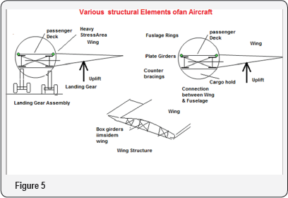
Various structural components and loadings are shown in the above sketches. Design principles of the various components are given briefly below.
The wings
They provide the necessary lift and drag forces to float and move the airplane by forcing air through its engines and thrust forward. The wings are of lightweight aluminium alloy structures covered by thin aluminium skin fixed on the structures. The structures are designed in cellular configuration to reduce the weight and give adequate strength against all imposed forces, to further reduce the weight and give additional strength, carbon fibres are extensively used specially on the skin which helps to withstand the tearing action of the passing wind. The fuel tanks are installed inside the wing structures. The landing gears are fixed under the wing structures which have to be designed for withstanding the heavy weight of the plane while on ground and during landing. These are specially designed for high strength against fatigue due to repetitive loadings. The wings are designed to hold the engines and stand the thrust and lift loadings. The wings are fitted with aelerons to provide additional lift during takeoff and help during descent of the aircraft.
The fuselage
It is the main body of the plane to accommodate the passenger and cargo facilities, machineries, other accessories like the rudder, fin, rear elevator, aeleron etc for movement and flight controls. The fuselage is a composite structure made of series of oval shaped frames interconnected and integrated with series of bracings and beams and girders. The most of the whole structure against these six directions need to be analysed. The six motions include roll, pitch, yaw, surge, heave and sway. During flight the fuselage is subjected to any or combination of these forces and therefore the structures have to be designed accordingly These are big exercises that needs to critical part of the fuselage is its connection with the wings which impart all sorts of loading like bending, torsion, shear etc. When afloat the entire fuselage acts as a floating beam having six degrees of free motion. Therefore stability be done with the help of computer programs and various design software's.


