Dynamical Loads on the Bronze Age Crossbar Wheel of Mercurago
Ali Batu*
Food, Nutrition and Gastronomy Science, Turkey
Submission: August 14, 2018; Published: August 30, 2018
*Corresponding author: Angelo Mazzù, University of Brescia, Department of Mechanical and Industrial Engineering, via Branze 38, 25123 Brescia, Italy, Tel:+390303715525; Email: angelo.mazzu@unibs.it
How to cite this article: Angelo M,Filippo M G. Dynamical Loads on the Bronze Age Crossbar Wheel of Mercurago. Glob J Arch & Anthropol. 2018; 6(2): 555684 DOI: 10.19080/GJAA.2018.06.555684
Abstract
This paper follows a previous study on a Bronze age crossbar wheel found in Mercurago (Italy), likely used for lightweight war chariot. In that study, structural and technological issue related to the wheel where assessed; its performance was evaluated by considering dynamical loads, due to bumping and curving, hypothesized based on typical values occurring on modern vehicles. In the present paper, a deeper insight into the dynamics of the wheel is presented. The dynamical loads on the wheel where obtained by means of a finite element model of the whole chariot, whose possible assembly was reconstructed based on both the wheel geometry and the structure of a coeval chariot found in Armenia. The chariot framework was supposed to be made by wooden members connected by leather joints. The cockpit floor was supposed to be in interwoven leather stripes. Two people (the driver and the warrior) were transported by the chariot. Two dynamical loading conditions were considered: bumping with one wheel over an obstacle at 40 km/h and running a 5 m radius curve at 20km/h. The results in terms of dynamic loads on the wheel significantly differ from the hypotheses introduced in the previous study, but the conclusions drawn about the structural issues of the wheel were confirmed.
Keywords: War chariot; Crossbar wheel; Vehicle dynamics; Structural issues; Bronze Age; Damping; Bumping; Curving; Density; Weight; Wheel; Warrior
Introduction
The diffusion of domesticated horses throughout Europe, occurred by the end of the third millennium B.C., was a key factor for the development of vehicles, as the increased transport speed stimulated the development of lighter and faster vehicles [1]. The chariot, a light, resistant two-wheeled vehicle, aimed at rapidly displacing one or two persons, was invented for war and ceremonies; likely started from the Near East, it subsequently spread all over Egypt and Europe and became a key power factor for ancient empires [2,3]. The chariots of Near East and Egypt communities in the second millennium B.C. had spoked wheels, particularly efficient in terms of strength/weight ratio [4,5].
The crossbar wheel found in the XIX century in Mercurago (Italy), dated between the XVIII and the XIII century B.C. [1], had a slightly lower technological level with respect to these, being the product of smaller and less organized communities. This wheel has a diametric bar (crossbar) with an inserted nave in the central hub; four thinner rods depart eccentrically on each side of the nave and terminate into the fellow. A previous study on this wheel [6] showed its complexity in terms of structural optimization and assembly technique, evidencing the key role of the inserted nave as anti-wear member and the optimized stiffness/weight ratio against radial loads. On the other hand, the study evidenced the intrinsic structural weakness of the wheel in curve, mainly related to the low bending stiffness of the eccentric rods against lateral loads. This weakness could explain why this kind of wheel was subsequently abandoned and replaced by the spoked wheel.
The structural analysis presented in [6] was carried out by static Finite Element (FE) models of the wheel. The external dynamical loads, due to severe conditions such as bumping on one wheel at 40 km/h and running along a 5 m radius curve at 20 km/h, were hypothesized based on load coefficients typically used for structural analyses of modern vehicles in similar running conditions [7]. The vertical load on the wheel impacting the obstacle was estimated multiplying the total static load by a dynamic coefficient equal to 2, whereas the lateral load in curving was estimated by assuming a centrifugal acceleration equal to 0.6 g, being g the gravitational acceleration. In the present paper, these hypotheses are verified by means of a dynamical analysis of the whole chariot. The chariot assembly was reconstructed based on an Armenian chariot found in Lchashen [1], which could be reasonably like the one to whom the Mercurago wheel could be attached. Some more insights, mainly related to the axle diameter, were obtained by a preliminary study on the chariot dynamics [8]. Dynamical FE analyses of the chariot with two passengers were carried out in the same conditions, hypothesized in [6] and the load exchanged by the wheels and the soil were evaluated.
FE Model
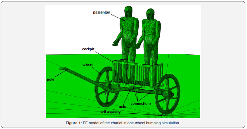
The FE model of the chariot with two passengers is shown in Figure 1. The overall dimensions of the chariot are 1995 mm in width, 3295 mm in length and 1080 mm in height. The soil is simulated by a rigid surface with a half-spherical asperity of height 60 mm; the whole soil is fixed by constraining all degrees of freedom of its reference point. All the other members are modeled by solid linear tetrahedra or bricks depending on the geometry of the meshed part. The main chariot members (pole, wheels, axle, and cockpit framework) are supposed to be in wood, modeled as an elastic isotropic material with elasticity modulus EW=11600 MPa, Poisson ratio nW=0.3 and density rW=615 kg/m3; the elastic properties are the same as for the hardwood considered in [6] along the grain direction. As known, wood is an orthotropic material [9]; however, given the thinness of all members, they are supposed to work mainly in bending with the wood grains being strained along their longitudinal direction, therefore the orthotropic effect is considered negligible. The connections between the wood members, as well as the cockpit floor, are supposed to be in interwoven leather stripes. This material also is supposed to be elastic isotropic with elasticity modulus EL=9000 MPa, Poisson ratio nL=0.35 and density rL=1000 kg/m3. The elastic properties were determined by imposing a maximum defection of the 5 mm thick cockpit floor of about 25 mm under the static load of the two passengers’ weight; the density was estimated based on the data published in [10]. A material damping with =2.5 and =0 according to the Rayleigh model was added to the leather properties definition. The two passengers are modeled in isotropic elastic material as well, with EP=1000 MPa, Poisson ratio nP=0.3 and density rP=1250 kg/m3. The elastic properties are arbitrary, as only the inertial effect of the passengers is of interest for the simulation. The density is such that the mass of each passenger is 80 kg; the overall mass of the chariot with the passengers is 202 kg. “Tie” type constraints are imposed at the interfaces between the leather connections and the pole, the axle and the cockpit; frictionless contact is imposed between the axle and the internal surfaces of the nave, as well as between the passengers and the cockpit; contact with coefficient of friction f=0.5 is imposed between the wheel rims and the soil. A horizontal rectilinear displacement corresponding to a traveling speed of 40 km/h was imposed at the front end of the pole in one-wheel bumping simulations; the same velocity was imposed as initial condition to all the members, in addition to a coherent rotational speed of the wheels. A curvilinear displacement along a circumference of radius 5 m corresponding to a tangent speed of 20 km/h was imposed to the pole end in the curving simulations; a rectilinear speed of 20 km/h, with coherent rotational speed of the wheels, was imposed as initial condition to all the members. Gravity was imposed to the whole model. Automatic mass scaling was allowed for speeding up the simulation; a maximum increment of 16.8% of the whole model mass was obtained during the simulation, which was considered acceptable.

Results
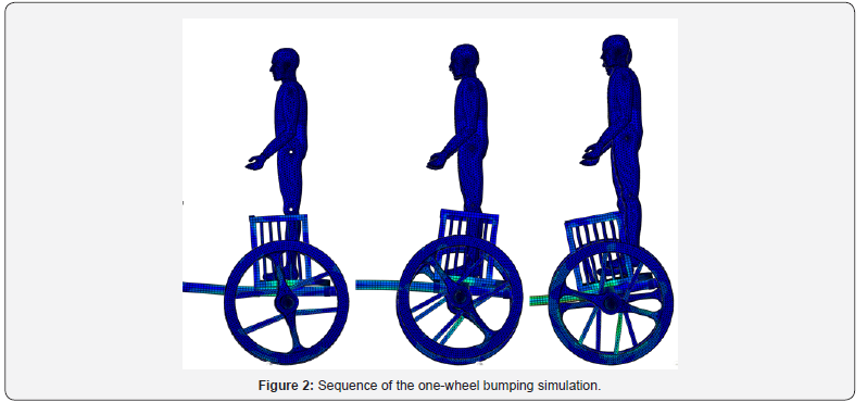
The maximum values of the dynamical loads on the vehicle, in terms of multiples of the gravity acceleration, were derived from the reaction forces of the fixed reference point of the soil (Figure 2). The maximum vertical dynamic load in one-wheel bumping resulted equal to about 11 g, whereas the lateral dynamic load in curving resulted equal to about 0.35 g. Comparing these results with the estimated dynamic coefficients assumed in [6], it is evident that in the previous work the loads in one-wheel bumping were underestimated by a factor of about 5.5, whereas in curving they were overestimated by a factor of about 1.7. The former factor shows that the criteria used for modern vehicles do not work well for ancient chariots, mainly due to their much less efficient suspension systems. On the contrary, the hypotheses previously assumed for lateral acceleration are acceptable as a higher bound.

Despite this difference between the assumed and calculated dynamical loads, the conclusions drawn about the structural issues of the Mercurago wheel in [6] are still valid. In fact, it was calculated that in condition of one-wheel bumping the overall wheel structure was largely in safety, by a factor much higher than the error on the input vertical load. It is confirmed that in this condition only local damage at the wheel rim surface could occur. On the other hand, in curving the eccentric rods were individuated as the weakest element of the wheel: this conclusion can be confirmed even though the updated lateral loads are lower than initially assumed.
Conclusion
A Finite Element model of a Bronze Age war chariot transporting two passengers was built for studying the dynamical loads on the Mercurago crossbar wheel. The structural issues of this wheel were assessed in a previous study by estimating the external dynamical loads by means of multiplying coefficients of the total wheel static load typical of modern vehicles. The chariot model was simulated in condition of one-wheel bumping and curving.
The obtained dynamic loads on the wheel resulted significantly different from the ones assumed in the previous study: the vertical load in one-wheel bumping resulted about 5.5 times higher than previously estimated, whereas the lateral load in curving resulted about 1.7 times lower than previously estimated. The former result is due to the lower efficiency of the ancient suspension system with respect to modern ones, whereas the second result shows that the previous assumption was acceptable. Despite the difference between the assumed and calculated dynamic loads, the conclusions drawn in the previous work about the structural issues of the wheel are confirmed.
References
- Piggott S (1983) The earliest Wheeled Transport-From the Atlantic Coast to the Caspian Sea. Cornell University Press, New York, USA.
- Rossi C, Chondros TG, Milidonis KF, Savino S, Russo F (2016) Ancient road transport devices: developments from the Bronze Age to the Roman Empire. Front Mech Eng 11(1): 12-25.
- Sandor BI (2004) The rise and decline of the Tutankhamun-class chariot. Oxf J Archaeol 23(2): 153-175.
- Sandor BI (2004) Tutankhamun’s chariots: secret treasures of engineering mechanics. Fatigue Fract Eng Mater Struct 27: 637-646.
- Rovetta A, Nasry I, Helmi A (2000) The chariot of the Egyptian Pharaoh Tut Ankh Amun in 1337 BC. kinematics and dynamics. Mech Mach Theory 35: 1013-1031.
- Mazzù A, Gambari FM, Bodini I, Pasinetti S, Sansoni G (2017) An engineering investigation on the Bronze Age crossbar wheel of Mercurago. J Archaeol Sci Rep 15: 138-149.
- Brown JC, Robertson J, Serpento ST (2002) Motor Vehicle Structures - Concepts and Fundamentals. Butterworth Heinemann, Oxford, UK.
- Mazzù A, Gambari FM, Uberti S, Bodini I, Pasinetti S, et al. (2018) An engineering study of a Bronze Age war chariot. IOP Conf. Ser.Mater Sci Eng 364: 012016.
- Green DW, Winandy JE, Kretschmann D (1999) Mechanical properties of wood. In: Wood Handbook-Wood as an Engineering Material. Gen. Tech. Rep. FPL-GTR-113 U.S. Department of Agriculture, Forest Service, Forest Products Laboratory, Madison, Wisconsin, USA.
- Yu W (2013) The Mechanical Properties of Leather in Relation to Softness. UMI Dissertation Publishing ProQuest LLC, Ann Arbor, MI, USA.


