


Brushless Direct Current Motor Modeling for Electric Vehicle Application by Optimized Speed and Angular Displacement Characteristics and Enhanced Electrical Safety Design Practices and Industry Standards Adoption
Pravin Sankhwar*
Department of Electrical Engineering, Houghton, United States
Submission: December 11,2024;Published:December 20, 2024
*Corresponding author:Pravin Sankhwar, Department of Electrical Engineering, Houghton, United States, Email : pravin1989vision@gmail.com
How to cite this article:Pravin S. Brushless Direct Current Motor Modeling for Electric Vehicle Application by Optimized Speed and Angular Displacement Characteristics and Enhanced Electrical Safety Design Practices and Industry Standards Adoption. Eng Technol Open Acc 2024; 6(2): 555682.DOI: 10.19080/ETOAJ.2024.06.555682
Abstract
Synchronous machines have excellent performance when compared to induction machines. Brushless dc motor is another form of synchronous motor wherein the dc excitation system for rotor has been removed. Brushless Direct Current Motor (BLDCM) do not use brushes as in conventional DC motors. Thus losses are less. Being a permanent magnet synchronous motor, it eliminates the requirement of separate DC supply to energize the rotor winding. After its invention studies were carried out to improve its performance. The study here is aimed at building a simple mathematical model which can be easily modified as per requirements by user. The model is based on the differential equations of BLDC motor. The BLDC equations were used to form a block diagram which was implemented in simulation software. A trapezoidal wave for back emf is assumed. However in actual case the wave is not perfect trapezoidal. MATLAB/SIMULINK was used to simulate the BLDC motor. However simulation results can also be obtained by using physical model which is an alternate way of modelling motor. The curves for angular speed Vs time and angular displacement Vs time were obtained using the simulated model. The performance of the machine was studied by using the stator resistance, self-inductance, mutual inductance, poles and flux densities produced. The choice of the material forms another part of our studies. For a surface mounted rotor with Ferrite and NdFeB, comparison of costs was studied. Comparison between Axial flux machines and Radial flux machines was also studied. Application of industry standards in increasing the safety of operation of electric motor was documented. Therefore, based on the review of the standards the vehicular safety was enhanced.
Keywords:Electric Vehicle; Angular Displacement; self-inductance; Brushless Direct Current Motor
Abbreviations:MATLAB: MATrix LABoratory; BLDCM: Brushless Direct Current Motor
Introduction
Brushless DC motors are synchronous electric motors powered by direct-current electricity and having electronic commutation systems, rather than mechanical commutators and brushes. Brushed DC motors have been in commercial use since 1886. BLDCM uses position information of uniform torque production. Hall sensors are used for sensing the position of the rotor and hence controlling the inverter that provides input to the motor. A BLDCM has permanent magnets which rotate and a fixed armature, eliminating the problems of connecting current to the moving armature. An electronic controller replaces the brush/commutator assembly of the brushed DC motor, which continually switches the phase to the windings to keep the motor turning. The controller performs similar timed power distribution by using a solid-state circuit rather than the brush/commutator system [1]. Limitations of brushed DC motors overcome by BLDC motors include lower efficiency and susceptibility of the commutator assembly to mechanical wear and consequent need for servicing, at the cost of potentially less rugged and more complex and expensive control electronics.
BLDC motors fulfill many functions originally performed by brushed DC motors, but cost and control complexity prevents BLDC motors from replacing brushed motors completely in lowest cost areas. Nevertheless, BLDC motors have come to dominate many applications particularly devices such as computer hard drives and CD/DVD players. Small cooling fans in electronic equipment are powered exclusively by BLDC motors. They can be found in cordless power tools where the increased efficiency of the motor leads to longer periods of use before the battery needs to be charged. BLDC motors are currently the most popular motor choice for model aircraft including helicopters. Their favorable power to weight ratios and large range of available sizes, from under 5 grams to large motors rated at thousands of watts, have revolutionized the market for electric-powered flight.
Types of Brushless Direct Current Motor
According to the flux linkages between stator to rotor we can
classify the motors as:
Radial Flux Machines: The machines in which the flux is
linked radially are termed as radial flux machines [2].
Axial Flux Machines: The machines in which we have axial
flux linkages are termed as axial flux machines. Because of the
axial flux it is possible to implement such machines in electric
vehicles [2]. The comparison between the two types of machines
is as follows in (Table 1).

BLDCM Back Emf wave and current
The back emf wave can be trapezoidal or sinusoidal. The back emf has a shape of trapezoid and currents have a quasi-square wave form. From the graph it is clear that at and instant summation of all the phase currents is equal to zero. Torque is equal to twice of the flux multiplied by current of each phase. This is because at any instant two of the phase currents are equal but opposite in sign and the third one is zero [3].
Magnetic Circuit Model
The magnetic circuit of BLDCM can be studied by taking into account the flux paths. The magnet flux leaving from North pole at the air gap crosses over to the stator. It splits into two equal sections, each traveling in the opposite direction and crossing the air gap toward South poles at the air gap. There is some leakage flux also. In magnetic circuit, R represents reluctance. Rl is reluctance to the leakage flux (ɸl). ɸg is the flux represented by bigger path. Rs is the reluctance of stator. Rg is the air gap reluctance. Rr is the rotor reluctance. ɸr is the flux in the rotor circuit [4].
The magnetic circuit can be simplified by considering the flux flowing through reluctances as shown in the magnetic circuit. The magnetic dipoles of rotor are shown as sources which produce flux. The reluctances are shown as resistance elements and flux flows through the two paths accordingly. The studies related to this magnetic model can be implemented to build a model using Ansoft Maxwell 3D [2]. But for the purpose of simplification, we have to form a state space model, and this state space representation can be used to simulate the motor on MATLAB/SIMULINK.
Construction and Operating Principles
BLDC motors are modified version of synchronous motor. BLDC motor can also be considered as a type of synchronous motor. It can also be stated that BLDC motor is permanent magnet synchronous motor. Sometimes it is also called inside out dc motor because its armature is placed on stator and the magnets are placed on the rotor. Its operating characteristics resemble that of dc motor. The rotor rotates at synchronous speed (Ns). The magnetic field generated by the stator and the magnetic field generated by the rotor rotate at same frequency. The rotor rotates at synchronous speed (Ns). . The slip is given by equation (1) [5],

Hence BLDC motor never experiences slip that is normally the case in an induction motor. BLDC motor stator can be wound for single-phase, two-phase and three-phase configurations. So there are BLDC motors depending upon the supply given to them singlephase, two-phase or three-phase. Three-phase motors are the most economical [6] and widely used. The stator windings are similar to those in a polyphase ac motor, and the rotor is composed of one or more permanent magnets. Brushless dc motors are different from ac synchronous motors in that the former incorporates some means to detect the rotor position (or magnetic poles) to produce signals to control the electronic switches. The construction of the motor i.e. stator and rotor will be discussed in the next few sections.
Stator
The stator means the stationary part of the motor. For a BLDC motor stacked steel laminations are used. The stator windings are placed in the slots. These slots are axially cut along the inner periphery of the stator as shown in (Figure 1). It is very much clear that, the stator is exactly same as that of an induction motor. However, the distribution of the winding is different in BLDCM.
There are two types of stator windings variants: trapezoidal and sinusoidal motors. This differentiation is made on the basis of the interconnection of coils in the stator windings to give the different types of back Electromotive Force (EMF). As their names indicate, the trapezoidal motor gives a back EMF in the form of a trapezoidal wave and the sinusoidal motor’s back EMF is in the form of sinusoidal wave. In addition to the back EMF, the phase current also has trapezoidal and sinusoidal variations in the respective types of motor. When we compare the two motors we see that the torque output by a sinusoidal BLDC is smoother than Trapezoidal BLDC. However, it result in increase in total cost of the BLDC motor, as the sinusoidal motors take extra winding interconnections because of the coils distribution on the stator periphery, thereby increasing the copper intake by the stator windings. Depending upon the control power supply capability, the motor with the correct voltage rating of the stator can be chosen. Forty-eight volts, or less voltage rated motors are used in automotive, robotics, small arm movements and so on. Motors with 100 volts, or higher ratings, are used in appliances, automation and in industrial applications.

Rotor
A permanent magnet is used to make the rotor whose poles can be varied from two to eight. The magnetic field density required in the rotor is different for different motor; accordingly a proper magnetic material is chosen to make the rotor. Traditionally ferrite magnets are used to make permanent magnets. With technological advancement, rare earth alloy magnets have gained popularity. The advantage of ferrite magnet is it is less expensive. But it has low flux density. The quality of alloy material to provide high magnetic density per volume enables the rotor to become compact for the same electrical torque. These alloy magnets also improve the size-to-weight ratio and in addition give higher torque for the same size motor using ferrite magnets. Neodymium (Nd), Samarium Cobalt (SmCo) and the alloy of Neodymium, Ferrite and Boron (NdFeB) are some examples of rare earth alloy magnets [3]. Research is going on to improve the flux density to make the rotor more compact.
Cost Consideration of BLDCM
The purpose of permanent magnet rotor is to provide rotor flux
which links to the stator flux. Use of permanent magnet increases
the cost of the machine thereby hindering its use for common
people. Due to this increased cost it has been a prominent concern
for researchers towards reduction of motor cost. The cost can be
compared on the basis of the components of the motor. Following
parameters/components are used to compare the cost:
i. Lamination steel grades
ii. Diameter of Cu wire
iii. Permanent magnet material: Ferrite and Neodymium
Iron Boron (NdFeB)
iv. Shapes of NdFeB
v. Number phases of stator: single phase, two phase, three
phase
Inferences from Figure in [6] are mentioned below:
i. M800 steel lamination has the least cost over other types
of laminations considered here and, hence, is a better choice for
making the core material for the stator and rotor.
ii. The diameter of Cu wire must be kept between 0.71-1.81
mm so that its cost is minimal.
iii. The shape of the rotor must be Block shaped because its
cost factor varies between min. 1 and max. 1.6.
iv. Sintered and Anisotropic Ferrite sixth generation has the
least cost factor; hence, it is a better choice for PM material.
Torque Ripple
BLDC encounters several vibrations because the torque of the machine is not perfectly uniform. It mainly depends on the material of the rotor and number of phases. Hence over 180 degrees of rotation of rotor the torque characteristics are obtained with different configurations of machines in [6]. From [6], it is inferred that electromagnetic torque ripple is lowest with 3-phase Ferrite PM concept. Torque ripple is highest in 1-phase Ferrite PM motor. 3-phase NdFeB has similar torque characteristics but it has higher cost than 3-phase Ferrite PM. Hence against torque ripple three phase with Ferrite as PM becomes a most acceptable choice.
The comparison of costs of BLDCM is shown in Figure. On the
basis of following components of motor:
i. Stator
ii. Stator winding
iii. Rotor
iv. Rotor can
v. Winding contacts
vi. Housing
vii. Rotor sensor
viii. Power electronics
Further from the study [6] it found that 3 phase BLDC with Ferrite or NdFeB is best suitable and economical option.
Engineering Standards and Vehicular Safety
The standards that govern the design of electric motors include
the International Electrotechnical Commission (IEC) 60034
standard series, NEMA, and MG1 standards. These standards
govern the manufacturing, safety, and other components involved.
Brushless DC motors have evolved from brushed DC motors. These
utilize electronic speed controllers in comparison to mechanical
commutation in brushed motors. The inherent advantages of
BLDCM in improved efficiency and performance, durability, ease
of maintenance, cheaper cost, and cost-effective applications
make them an ideal fit for many industrial machinery and electric
vehicles. Unlike for traditional internal combustion engines,
mileage is based on total miles per gasoline, for EVs, the motors
consume electric power and thus miles per kWh energy becomes
a measure for mileage. There is a list of applicable standards
for compliance for electric motors in the automobile industry.
Critical compliance is based on IEC 60034, which governs the
design considerations for acceptable motor composition and
performance criteria.
i. IEC 60034: International Standard for Rotating Electrical
Machines
ii. ISO 9001: Quality Management System
iii. Iso 14001: Environmental Management System
iv. Energy-Efficiency Standards (e.g., NEMA Premium, IE3)
v. Hazardous Location Standards (e.g. NEC, IECEx)
Some key elements that appear on motor nameplates are Service factor, Rated Load Current, Rated Voltage, Locked Rotor Current, Design Letter and Torque Profile, and Ingress Protection. With the simplistic design presented in this paper and compliance with the industry standards vehicular safety is enhanced.
Assumptions Used in Modelling
The modelling of the motor requires certain assumptions. For
the purpose of study we need to eliminate those agents which
make it more complicated. Hence it’s essential to consider certain
ideal conditions that are not possible with practical motors. The
assumptions are discussed below:
i. Symmetrical Three Phase Star connected windings:
Every three phase machine either has star of delta connected
stator winding, here we have star connected stator windings. The
windings are symmetrically placed in the stator slots [7].
ii. Balanced system: A balanced three phase supply is fed
(square wave input [4]) is supplied to the stator which produces
uniform torque for the motor. The impedence of each phase
winding is equal [7].
iii. Rotor has surface mounted design: The magnets are
mounted on the surface of the rotor so that there is a smooth
surface over the rotor. This insures that stator self inductances
become independent of rotor position [7].
iv. Back emf has exact trapezoidal waveform: The back emf
here is taken as trapezoidal. The shape of this wave is assumed to
be exact trapezoidal. However this exactness reduces the precision
of modelling and simulation. But it simplifies our problem
considerably. Study of exact trapezoidal back emf waveform is
another field of research [8]. Although the use of exact trapezoidal
waveform maximizes the errors [7].
v. Uniform air gap: Similar to cylindrical rotor synchronous
machines the air gap between stator and rotor in BLDC motor is
assumed uniform [7].
vi. Mutual inductance is assumed constant when the motor
runs [7].
vii. The load torque is assumed constant.
Modelling of Brushless Direct Current Motor
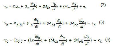
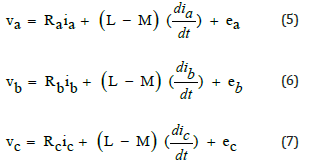
In three phase Y connected stator windings (as shown in (Figure 2)) let La, Lb, Lc represents the self inductance of each phase winding. Mab, Mbc, Mca, Mac, Mba, Mcb, are the mutual inductance between each phase winding. ea, eb, ec represents the back emfs of each phase and va, vb, vc are the supply voltages to the stator windings.

The Y connected windings (shown in (Figure 2)) has an added advantage that there is no effect of third harmonic currents on the performance of rotor. Though not readily apparent mathematically (i.e. third harmonic currents make the sum of phases currents non zero), the brushless DC motor drive satisfies this current constraint (ia + ib + ic= 0) as well [4].
In ideal case an inductive winding has zero resistance. Let the resistances of three-phase windings be represented as Ra, Rb, Rc. Now we use Kirchoff’s current and voltage laws in circuit theory. The following equations [7] [9] are obtained by applying KCL and KVL to the stator windings of the motor shown in (Figure 2).
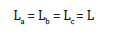
We have assumed that the rotor has a surface-mounted design, which is generally the case for today’s BLDC motors, there are no salient poles such that the stator self inductances are independent of the rotor position, hence:
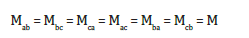
Also, the mutual inductances will have following form:
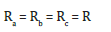
For three phase balanced system, all the phase resistances are equal
Hence equations (1), (2), (3) reduces to,
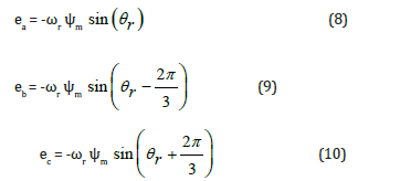
The back emf waves for each phase windings can be expressed as shown below,
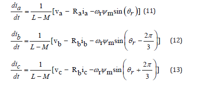
The following state space model is obtained:
Block diagram are formed using equations which are in terms of complex frequency, s and each element/parameter is converted using Laplace transform. Taking Laplace transform for (11) we get,
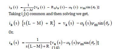
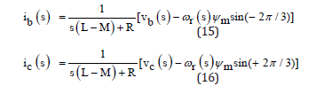
Similarly, we can reduce equations (12) and (13) to (15) and (16) as shown below,
The electrical torque developed (Te) is given by equation (17),
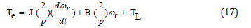
Where B represents the friction constant to rotor and J is the rotor inertia. TL is load toque.
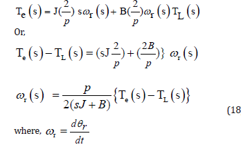
Taking Laplace transform we get equation (18),
Taking Laplace transform we get,
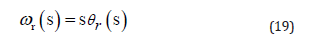
The angular displacement can be obtained by integrating angular speed. Since we have obtained the Laplace equations we can use them to form a control system block diagram. Using the basics of control system the above equations (14), 15), (16), (17) and (19) can be used to develop a block diagram in MATLAB/ SIMULINK.
MATLAB/SIMULINK Model
Block diagram obtained in the previous chapter can be implemented in MATLAB/SIMULINK to simulate BLDCM. MATLAB/SIMULINK block library provides all the necessary components that we need for modelling through a given set of differential equations. Other simulation software such as AnSoft Maxwell 3D, SPICE etc can also be used. In (Figure 3) MATLAB/ SIMULINK model is shown.
Subsystems developed in our studies are namely input block, motor current block, torque block, feedback block and integrator. Each subsystem/block is explained in detail as follows.
Input Block
(Figure 4) shows the components of the input block which comprises of pulse generators. Pulse generators produce square shaped pulses for a predetermined period of time given by user. Three phase square wave input is given to the motor as shown in (Figure 4). Three pulse generators are used to supply voltage each phase winding.
Motor Current Block
In this block there is an error detector that performs (va-eb). As
it is clear from equations (14), (15) and (16), (va-eb) is multiplied
by 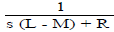
Torque Block
Firstly three phase currents are added (we get ia + ib + ic) using two error detectors. Their summation is multiplied by gain (p/2 ψm , flux per pole) to obtain electrical torque developed (Te). Load torque (TL) is then subtracted from Te using another error detector. From equation (18),
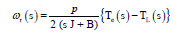
Hence Te(s) - TL(s) obtained is multiplied by 


Feedback Block
Closed loop systems are less sensitive to external disturbances and internal variations of system parameters. The control action is dependent on the output. We use a feedback block which provides back emf as a feedback which helps to generate uniform torque for the motor. ωr is multiplied with sine function and ψm (flux) to obtain eb (back emf). Its components are shown in (Figure 7).
Integrator
The integrator block integrates angular displacement of rotor, ωr and gives angular displacement θr. as output which is read on a scope (see equation (19)). The integrator block is shown in (Figure 8).
Results
The parameters defined in MATLAB/SIMULINK model were
given values as mentioned below:
Resistance, R= 11.05 Ohm
Self Inductance, L= 0.0215 H
Mutual Inductance, M= 0.002 H
Air Gap Flux, ψm = 0.11Wb
Moment of Inertia of rotor, J= 0.0001kgm2
Friction constant, B= 0.001 N/rad/s
Poles, p= 4
Supply Voltage, V= 20 volt
Load Torque, TL= 0.0005 Nm
The results of simulation are obtained as characteristic curves of angular speed (ωr) Vs time (t) and angular displacement (θr) Vs time (t), With speed (rad/sec) on y-axis and time (sec) on x-axis as shown in the (Figure 9). and displacement (radian) on y axis and time (t) on x-axis. Curves are obtained for set of values given above. The values of speed, torque and power are calculated and shown in (Table 2).


Angular displacement of rotor Vs time characteristics is also obtained as shown in (Figure 10). It is found that displacement is directly proportional to time.
Discussion
Being a simple model it can be easily be used to study the performance with least number of parameters (R, L, M, B, J, p, V, ψm). The main advantage of this model lies in the assumptions taken to derive the motor equations. We can neglect each assumption one by one and can obtain a suitable model and hence obtain the performance characteristics of the brushless dc motor. Synchronous motors have excellent performance over any other machine developed so far. BLDC motors belong to the family of synchronous motors. Hence use of BLDC motor will prove to be a boon and a technical advancement to modern drive system. The selection of magnetic material for the rotor is another field of research. Studies performed over BLDC motor used for water pump shows that Ferrite and NdFeB is most suitable both economically and in performance
BLDC motor is still one of a small-scale motor. It is used in small electric devices such as CD players, hard disk drives, or even small electric cars. Use of more economical motor as proposed in the studies we can have large scale production of these motors especially for electric vehicles. The use of such high performance machines can reduce the green house emissions. Hence reducing the carbon foot print of the manufacturer and person who uses such motors. Being a newly developed motor, its studies are of major concern. The simulated motor here can be used to study the characteristics of BLDC motor that are used in vehicles, CD players, pumps etc. If this model is considered as a base for modelling other motors of same type then it will help manufacturers greatly in designing required before manufacturing of motor.
Conclusion
A simple BLDC Motor modelling was performed. A control system block diagram for the motor differential equations was obtained. Its simulation was done on MATLAB/SIMULINK. The performance characteristics were obtained. The model here will make it simpler to obtain characteristics for speed Vs time and displacement Vs time. Model presented here can be modified as per user’s requirement. Electric vehicles, CD players, pumps etc use BLDCM. Hence this model can help study their characteristics. Synchronous machines have excellent performance over any other rotating machine. BLDCM is just advancement with permanent magnet rotor. This rotor makes the machine expensive. There is no need for extra field excitation. Hence there is small savings. But in future a large scale production can lead to reduction in cost. It is also found that use of Ferrite and NdFeB material for rotor magnets becomes a better option. Electric vehicle being less polluting will reduce Green House Emission. The main advantage of this motor over other types of motor in the same rating is higher ratio of produced torque per weight, lower moment of inertia, and less maintenance. Electric vehicle though not much in use on Indian roads will come in large use in coming years. Hence studies related to them can be carried out using the developed MATLAB/ SIMULINK model [10].
References
- Azab M (2022) Comparative Study of BLDC Motor Drives with Different Approaches: FCS-Model Predictive Control and Hysteresis Current Control. World Electric Vehicle Journal 13(7): 112.
- Rahim NA, Ping HW, Tadjuddin M (2007) Design of Axial Flux Permanent Magnet Brushless DC Motor for Direct Drive of Electric Vehicle. IEEE Power Engineering Society General Meeting, Tampa, FL, USA, pp. 1-6.
- Yedamale P (2003) Microchip Technology Inc. “Brushless DC (BLDC) Motor Fundamentals”, AN855, Microchip Technology Inc, Arizona, United States.
- Duane Hanselman (2003) Brushless Permanent Magnet Motor Design. Second Edition, Chapter 4, The Writers' Collective, Rhode Island, United States, pp.186-200.
- Husain A (2009) Electric machines. Second Edition, Dhanpat Rai Publications, New Delhi, India, pp. 419-439.
- Hembach H, Evans SA, Gerling D (2008) Systematic comparison of BLDC motors for small automotive water pump applications.18th International Conference on Electrical Machines, Vilamoura, Portugal, pp.1-5.
- Saarulatha T, Yaknapriya V, Muthukumar T, Saravanan S (2014) Proportional Integral and Derivative Controller for BLDC Motor. International Journal of Research in Advent Technology 2(12): 1-5.
- Jeon YS, Mok HS, Choe GH, Kim DK, Ryu JS (2000) A new simulation model of BLDC motor with real back EMF waveform," COMPEL 2000. 7th Workshop on Computers in Power Electronics. Proceedings (Cat. No.00TH8535), Blacksburg, VA, USA, pp. 217-220.
- Poonsawat Sawatdipong,T hanatchai Kulworawanichpong (2008) Speed Regulation of a Small BLDC Motor Using Genetic-Based Proportional Control. International Journal of Electrical and Computer Engineering 2(11): 2486-2491.
- Baldursson Stefan (2005) BLDC Motor Modelling and Control - A Matlab®/Simulink® Implementation.


