


Thermo-Hydraulic Analysis of Shell and Externally Finned Tubes Heat Exchangers Optimized Connected Through Clamps and Using Non-Spherical NanoparticlesI
Élcio Nogueira*
Department of Mechanical and Energy of State University of Rio de Janeiro, FAT/UERJ, Resende, Brazil
Submission: June 13, 2023; Published: June 28, 2023
*Corresponding author: Élcio Nogueira, Department of Mechanical and Energy of State University of Rio de Janeiro, FAT/UERJ, Resende, Brazil
How to cite this article: Élcio N. Thermo-Hydraulic Analysis of Shell and Externally Finned Tubes Heat Exchangers Optimized Connected Through Clamps and Using Non-Spherical Nanoparticles. Eng Technol Open Acc. 2023; 5(2): 555660. DOI: 10.19080/ETOAJ.2023.05.555660
Abstract
The objective is to cool machine oil with seawater using externally finned shell and tube heat exchangers. The two fundamental parameters for optimizing the oil cooling process are the number of finned tubes per heat exchanger and the number of heat exchangers connected through clamps. Non-spherical nanoparticles in the cylindrical form of Boehmite Alumina are incorporated into the water for performance analysis, with a volume fraction equal to 5.0%. Oil enters the tubes at 98.0 °C, and water flows into the annular region at an inlet temperature equal to 20.0 °C. The oil flow rate is fixed, equal to 2.5 kg/s, and the water + nanoparticles flow rate varies from 1.0 kg/s to 5.0 kg/s. The thermal efficiency of the heat exchanger is used to obtain the thermal effectiveness, the heat transfer rate, the fluid outlet temperatures, and the thermal irreversibility. Pressure drops in the tubes and the annular region are used to obtain viscous irreversibility. The Bejan number is obtained for the overall performance analysis of the heat exchanger. The number of fins per tube is 28, and the flow configuration is counter-flow. It is shown that the optimal performance configuration is obtained for nine finned tubes per heat exchanger and some connected heat exchangers equal to 4 for a fixed tube internal diameter equal to 127 mm.
Keywords: Shell and Tube Heat Exchanger; Externally Finned Tubes; Thermal Efficiency; Bejan Number; Non-spherical Nanoparticles; CFD - Computational Fluid Dynamics; GPHE -Gasket Plate Heat Exchanger; NTU - Number of Thermal Units
Introduction
The objective is to cool machine oil with seawater using externally finned shell and tube heat exchangers. The two fundamental parameters for optimizing the oil cooling process are the number of finned tubes per heat exchanger and the number of heat exchangers connected through clamps. Extended surfaces are applicable when finned tubes are used to improve heat transfer passively. Experimental and numerical investigations have been conducted using various types of fluids. Most of the fins are strips of metal with surfaces positioned longitudinally along the axis of the tube, but it is observed that literature is scarce on tubes with external fins. Heidar Sadeghzadeh et al. [1] study shell and finned tube heat exchanger. They use nine physical parameters as a reference, and the main parameters are tube diameter, length, number of tubes, and fins. They determine the coefficients related to heat transfer and pressure drop using the “Modified Delaware” technique. Achieve optimal compromise between heat transfer rate and pressure drop. The ideal heat transfer rate ranges from 3517 to 7075 kW, and the perfect pressure drop ranges from 3.8 to 46.7 kPa.
Faraz Afshari et al. [2] use nanoparticles to analyze the thermal performance of a shell and finned tube heat exchangers. They use Fe2O3 nanoparticles at concentrations of 1.0%, 1.5% and 2.0%. They use the ANSYS Fluent software for numerical simulation and report that the increase in the concentration of nanoparticles allows for greater thermal efficiency and that a volumetric fraction equal to 2.0% allows a 19.1% increase in the heat transfer rate. Prottay Malakar et al. [3] perform the performance study of double tube heat exchangers connected by clamps (hairpins). The work aims to obtain geometric parameters that optimize heat exchange and pressure drop. Furthermore, the configuration under analysis seeks to achieve the best costbenefit ratio for machine oil cooling since the reduction in pressure drop impacts the energy per unit of time generated by the pumping system.
Shiva Kumar et al. [4] analyze the thermal performance of concentric tube heat exchangers using the passive transfer technique. They use longitudinal profiles of rectangular fins, parabolic fins, and triangular fins. The mass flow rates of the fluids vary, and the base and height of the fin are kept constant. They conclude that the finned system allows higher heat transfer rates than tubes without fins. Furthermore, a rectangular profile fin configuration obtained the highest heat transfer rates.
Muhammad Ishaq et al. [5] evaluate the performance of diamond-shaped fins and claim to be pioneering work in finned tube heat exchangers. The method used in the analysis allows the automatic transformation of triangular and rectangular profiles. Furthermore, they use the finite element technique and introduce variations in the height and width of the fins, for analysis of thermal performance and viscous dissipation, for a ratio between the radii of the inner and outer tubes equal to 0.25.
Zafar IQBAL et al. [6] investigate finned rings with longitudinal ends, and the work aims to obtain the most favourable optimized configurations using the finite element method and genetic algorithm. Muhammad Ishaq et al. [7] investigated a double tube heat exchanger with triangular ends. They conclude that the thermal resistance between the media, fluid and solid, plays a fundamental role in the design of the heat exchanger. Ghazala Ashraf et al. [8] use the finite difference techniques in an externally finned shell and tube heat exchanger. They analyze the variations in fin height, thermal conductivities, and the number of fins to obtain optimal configurations. They use results from the literature to validate the procedure and conclude that the number and the height of ends are the most effective geometric parameters.
G. Arvind Rao & Yeshyahou Levy [9] assume that the practical use of correlations in finned tube heat exchangers is limited by the number of parameters needed to evaluate the friction factor and the Nusselt number properly. Despite this, they present a methodology to assess the performance of a finned tube heat exchanger. The correlations for smooth tube flow and flat plate flow are used in the analysis. They make numerical adjustments through successive substitutions and compare the results obtained with works in the literature to validate the model developed. They conclude that adding fins reduces the Nusselt number and that the increase in area is responsible for the higher heat transfer rate. Grzegorz Górecki et al. [10] performed a tubular heat exchanger project consisting of finned heat tubes and an experimental study and modeling test. Develops the thermal model using empirical correlations. They determine calculation parameters for the exchanger under analysis, using the “brute force” method for global cost optimization. The mathematical modeling fits the experimental results, with a maximum relative difference of 10%.
Ayon Mahmud et al. [11] designed a compact shell and tube heat exchanger to obtain high thermal efficiency and minimum cost. The heat exchanger under analysis contains inner tubes with axes parallel to the shell to cool oil using seawater. They report that limits were established for the difference in fluid outlet temperatures and total pressure drop as fundamental parameters for minimizing cost and maximizing thermal effectiveness. Mostafa Monfared et al. [12] studied a double tube heat exchanger to analyze the shape of Boehmite alumina nanoparticles on the entropy generation characteristics. The non-spherical nanoparticles were dispersed in mixtures of water-ethylene glycol (50%), and the used nanoparticles are cylindrical, blade, platelet, and brick. They have determined the entropy generation rates and thermal and viscous irreversibility numerically. Non-spherical nanoparticles have higher thermal performance than spherical nanoparticles. However, they conclude that non-spherical nanoparticles have a higher viscous entropy generation rate.
Adrian Bejan [13] emphasizes his works on analyzing thermodynamic irreversibility related to heat and mass transfer in terms of minimizing entropy generation in mechanical devices. The review focuses on the mechanisms responsible for entropy generation and how to balance thermal and viscous irreversibilities. Ahmad Fakheri [14] defines thermal efficiency for heat exchangers based on the second law of thermodynamics. It demonstrates that a corresponding ideal heat exchanger exists with the same AU, the exact arithmetic mean temperature difference, and the same inlet temperature ratio between cold and hot fluids. The ideal heat exchanger transfers the maximum heat, making it more effective and less irreversible. Heat exchanger efficiency is defined as the ratio of the heat transferred by the actual heat exchanger to the heat that the ideal heat exchanger would transfer. The concept of thermal efficiency for heat exchangers provides an alternative for analyzing heat exchangers.
Seyed Ali Ashrafizadeh [15] found that the second law of thermodynamics has been applied more frequently in recent decades to analyze heat exchangers. He states that many researchers consider minimization of entropy generation as an objective in the design of heat exchangers. However, he reports that other researchers reject the entropy generation minimization (EGM) philosophy. He develops a study to bring the two points of view closer together and presents two types of heat exchangers: “process” and “utility.” Furthermore, it shows that the EGM philosophy can only be applied to “utility” heat exchangers. He develops a mathematical model to investigate the effects of various parameters on exergy loss. It validates the model through experimental data using tubular heat exchangers. It simulates the process and utility heat exchangers, and the results indicated no real minimum point for exergy losses concerning the imposed restrictions.
Nogueir É [16] uses the thermal efficiency of heat exchangers to analyze shell and tube, heat exchangers. Water flows into the shell with an inlet temperature of 27°C. Water-ethylene glycol, with volumetric fractions of silver nanoparticles (Ag) or aluminum dioxide (Al2O3), flows through the tube with an inlet temperature equal to 90°C. The flow of ethylene glycol varies from 0.01 to 0.50 kg/s, and the water flow rate in the shell is kept constant, equal to 0.23 kg/s. Obtain results for thermal parameters by changing the volumetric fraction of the nanoparticles. It concludes that the flow regime significantly affects the performance of the heat exchanger.
Nogueira É [17] uses concepts of thermal efficiency of heat exchangers for thermal analysis of shell and tube condenser and uses Freon 134a as refrigerant flowing in the shell. The analysis includes three regions along the shell path: superheated steam, saturated steam, and saturated liquid. Each region contains four tubes, consisting of 12 tubes in all. Deflectors are included in the superheated vapor region. Temperature, efficiency, and effectiveness profiles were obtained for the three regions, with waterbased aluminum oxide nanoparticles flowing in the tubes. The nanofluid flow rate varies from 0.05 kg/s to 0.40 kg/s, and the refrigerant flow rate is fixed, equal to 0.20 kg/s. It performs a comparative analysis with experimental results obtained in the literature for steam pressure equal to 1.2 Mpa and water flow equal to 0.41 kg/s.
Methodology
It analyses configurations of heat exchangers with finned inner tubes, as shown in (Figures 1 & 2) shows six shell and tubes heat exchangers connected through a clamp. This type of configuration, called hairpin in the literature, is used to optimize the space where heat exchangers will be installe d. (Table 1) presents the properties of the oil, water, and Alumina. For performance analysis, the non-spherical cylindrical Alumina nanoparticles, with a volume fraction equal to 5.0%, will be associated with the oil (Figures 1 & 2).
(Table 2) presents the coefficients that characterize the non-spherical cylindrical shape of nanoparticles in dynamic viscosity and thermal conductivity. The formulation, with the data necessary to determine the quantities of interest in the analysis, is described below.


Thi and Tci are the inlet temperatures of the hot and cold fluids, respectively.
NHE is the number of heat exchangers connected by hairpin and considered for analysis.

NTube is the number of finned tubes per heat exchanger unit.
LTube is the length of each heat exchanger unit.
LTotal is the total length considered for the heat exchanger.
ΔFin and NFin are the fin thickness and the number of fins per tube.
kW is the thermal conductivity of the fin material.
Dhi and Dho are the inner and outer diameters of the tubes.
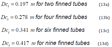
Dci is the inner diameter of the shell.
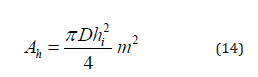
Ah is the cross-sectional area for internal flow in the tube.
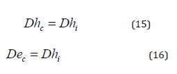
Dhc and Dec are the hydraulic and equivalent diameters for the tubes.
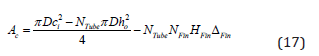
Ac is the cross-sectional area for flow outside the tubes.
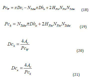
Dch and Dce are the hydraulic and equivalent diameters associated with the annular region.
ATotal is the heat transfer area for the configurations under analysis.
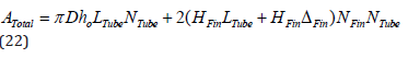
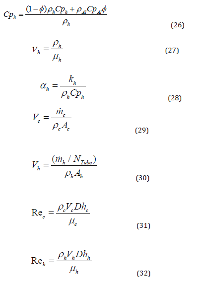
For the compound oil + Boehmite Alumina Nanoparticles, we have [12]:
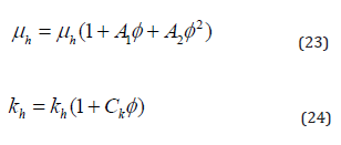
φ is the volume fraction of Boehmite Alumina Nanoparticles. A1 = 37.1, A2 = 904.4 e 2.61 Ck = are constants associated with cylindrical non-spherical nanoparticles [12].
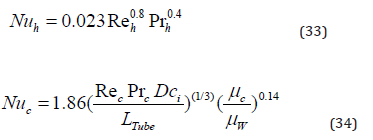
Rec and Reh are the Reynolds numbers associated with the cold and hot fluids.
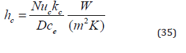
Nuc and Nuh are the Nusselt numbers associated with the cold and hot fluids, respectively. μW is the absolute viscosity near the surface that exchanges heat with the fluid.
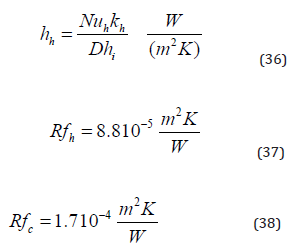
Rfc and Rfh are the fouling factors for water and oil, respectively.
ηFin is the efficiency associated with the fin.
Uo is the overall heat transfer coefficient.
Cc and Ch are the heat capacities associated with cold and hot fluids. Cmin is the smallest of the heat capacities.
NTU is the number of thermal units associated with the configuration under analysis.
ηT is the thermal efficiency of the heat exchanger [0.14].
εT is the thermal effectiveness associated with the configuration under analysis.
Q is the heat transfer rate associated with the configuration under analysis.

Tho and Tco are the outlet temperatures of the hot and cold fluids, respectively.
σT and SgenT are the thermal irreversibility and the thermal entropy generation rate.
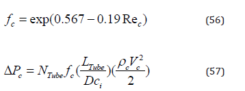
fc is the friction factor in the annular region. ΔPc is the pressure drop in the annular region.
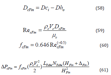
ΔPcFin is the pressure drop associated with the set of fins of the configuration under analysis.
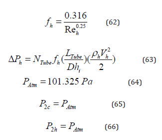
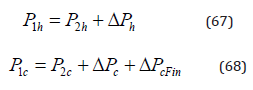
P2c and P2h are the outlet pressures of the cold and hot fluids.
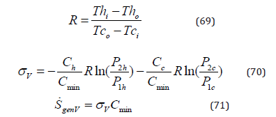
σV and SgenV are the viscous irreversibility and the viscous entropy generation rate.
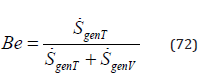
Be is the Bejan thermodynamic number [13].
Results and Discussion
Without Nanoparticles
Thermal efficiency for pure water flowing in the annular region is represented by (Figure 3). The thermal efficiency increases with the variation of the Reynolds number in the annular region, reaching a maximum value (ηT = 1.0) for high water flows. The maximum value for the Reynolds number decreases with the addition of finned tubes as a function of the increase in area for the water flow. Low values for thermal efficiency mean high thermal irreversibility and, consequently, high heat transfer rate. As the heat exchangers aim to obtain the highest possible heat transfer rate between the fluids, high values for thermal efficiency are not desirable (Figures 3-6).
(Figures 4 & 5) show the thermal effectiveness and heat transfer rate, respectively. The thermal effectiveness decreases with the increase of the Reynolds number, as there is greater energy absorption by the greater mass of water, and the heat exchange between the fluids decreases. With the increase in the number of finned tubes, the thermal effectiveness grows, demonstrating a higher rate of heat transfer between the fluids concerning the maximum heat transfer rate possible for the configuration under analysis. Effectiveness is maximum for low Reynolds values and equals the maximum actual heat transfer rate possible. Thermal effectiveness increases with the increase in the number of finned tubes. The heat transfer rate increases with the increase in the number of finned tubes, and the highest value obtained among those presented is related to nine tubes, which have minimum effectiveness close to 0.85 (Figure 7).


The oil outlet temperature is represented in (Figure 6). The oil outlet temperature decreases with increasing water flow, and the minimum temperature decreases with the increase in the number of finned tubes. For some finned tubes equal to 9, the lowest value obtained for the oil temperature is approximately equal to 40.0°C. For some finned tubes equal to 2, the minimum temperature obtained within the analyzed flow range is roughly equal to 67.0°C. As the number of finned tubes increases, the output temperature difference to the oil becomes insignificant, indicating that there is an ideal limit for the number of finned tubes in terms of cost-effectiveness. It should be noted, however, that this ideal limit for the number of finned tubes is linked to the diameter of the inner tube, which in this analysis is fixed and equal to 0.127 meters.
The total pressure drop in the annular region, prevalent to the total pressure drop in the heat exchanger, is shown in (Figure 7). The pressure drop increases with the increase in the water flow in the annular region. Pressure drop decreases with the increase in the number of finned tubes as a function of the increase in area. The observed drop is exceptionally high when comparing two finned tubes with nine finned tubes, on the order of 20 times for the highest flow in analysis. These high pressure drops highly impact the cost-benefit ratio for the heat exchanger.
The Bejan thermodynamic number is represented in (Figure 8). The Bejan number is the ratio of thermal entropy to the total entropy rate. The observed values are significantly low in all analyzed situations, but it is a price to pay to reach the objective. As expected, the thermal entropy generation rate versus the total entropy rate increases with the increase in the number of finned tubes as a function of the decrease in the total pressure drop. However, the difference between Bejan numbers indicates an ideal limit for the number of finned tubes for the configuration under analysis (Figure 8).
With Nanoparticles

The thermal efficiency with adding nanoparticles, (Figure 9), has similar profiles to the thermal efficiency without nanoparticles, Figure 3. The striking difference, however, lies in the reduction of the Reynolds number, which is six times smaller (250/60). The reduction affects all other parameters, thermal and hydraulic (Figures 9-12). Despite the reduction in the Reynolds number when adding nanoparticles, in numerical terms, the thermal effectiveness remained unchanged, (Figure 10), with high thermal effectiveness for lower flow rates and significantly influenced by the number of finned tubes.

The heat transfer rate between the fluids increased slightly with the addition of nanoparticles, with a closer approximation between the local and maximum heat transfer rate, (Figure 11). In addition to the reduction in the Reynolds number, the most significant influence observed is on the oil outlet temperature, (Figure 12). The decline is close to 20°C for the number of finned tubes equal to 2 and 5.0°C for the number of finned tubes equal to 9. It is important to note that the reduction in the outlet temperature decreases with the increase in the number of finned tubes, demonstrating that there is a limit to increasing the number of tubes when considering the costbenefit ratio in terms of thermal effects.
The total pressure drops in the annular region, with the introduction of nanoparticles, is represented in (Figure 13). There is a significant increase in pressure drop with the introduction of nanoparticles compared to the situation without nanoparticles. In addition, there is an increase in pressure drop, double for the number of finned tubes equal to 2 and 2.5 for the number of tubes equal to 9. Even so, the reduction in pressure drop related to the expansion from 2 finned tubes to 9 finned tubes remains high, equal to eight times. It is possible to observe a drop in the Bejan number with the introduction of nanoparticles, (Figure 14). This decrease means that the gain obtained for the thermal entropy generation rate is smaller than the viscous entropy generation rate increase. We know that an action taken to increase thermal effectiveness brings, on the other hand, an increase in thermal irreversibility. In this case, using nanoparticles is a price since the objective is to reduce the oil outlet temperature (Figures 13-15).


(Figure 15) presents a general picture of optimizing the machine oil cooling process through the shell and finned tube heat exchangers analysed here for some finned tubes equal to 9. The analysis encompasses introducing nanoparticles and expanding the number of heat exchangers. The first has already been the subject of a relatively comprehensive analysis, but its introduction broadens the view of the entire situation under investigation. Regarding the increase in the number of heat exchangers connected through clamps, the temperature drop is relatively high when comparing one heat exchanger and six heat exchangers. There is a decline from 70 °C to 40 °C without introducing nanoparticles. A relevant fact to consider, however, is that as the number of heat exchangers increases, the reduction in the outlet temperature decreases drastically, which becomes more evident with the introduction of nanoparticles. This little reduction is one of the factors to be considered in optimizing the heat exchanger since the increase in the number of heat exchangers increases costs and the need for a larger area for installation.
Conclusion
The work aims to cool machine oil with seawater using externally finned shell and tube heat exchangers. The two fundamental parameters for optimizing the oil cooling process are the number of finned tubes per heat exchanger and the number of heat exchangers connected through clamps.
Below is a summary of the main conclusions about the procedure carried out.
Without Nanoparticles
i. The highest value obtained for heat transfer is related to nine finned tubes, which have minimum effectiveness close to 0.85.
ii. For some finned tubes equal to 9, the lowest value obtained for the oil temperature is approximately 40.0°C. On the other hand, for several finned tubes equal to 2, the minimum temperature within the analysed flow range roughly equals 67.0°C.
iii. As the number of finned tubes increases, the output temperature difference to the oil becomes insignificant, indicating that there is an ideal limit for the number of finned tubes in terms of cost-effectiveness.
iv. The observed pressure drop is exceptionally high when comparing two finned tubes with nine finned tubes, with two finned tubes on the order of 20 times for the highest flow rate.
v. The difference between the Bejan number decreases with the increase in the number of finned tubes, indicating an ideal limit for the number of finned tubes.
vi. The temperature drop is relatively high when comparing one heat exchanger and six heat exchangers, with a decline from 70°C to 40°C, without introducing nanoparticles.
With Nanoparticles
i. The heat transfer rate between the fluids increased slightly with the addition of nanoparticles, with a closer approximation between local and maximum heat transfer rate.
ii. The most significant influence observed, with the inclusion of nanoparticles, is on the oil outlet temperature, and the reduction in the outlet temperature decreases with the increase in the number of finned tubes.
iii. There is a significant increase in pressure drop with the introduction of nanoparticles compared to the situation without nanoparticles. In this case, using nanoparticles is a price since the objective is to reduce the oil outlet temperature.
iv. As the number of heat exchangers increases, the outlet temperature decreases drastically. Furthermore, it increases costs and the need for a larger area for installation.
Nomenclature
Ach – channel cross-sectional free flow area, [m2]
Ae – heat transfer total area, [m2 ]
Achsine – channel cross-section transverse to the furrow, [m2 ]
b corrugation depth, [m]
– specific heat of the cold fluid, 
Cph – specific heat of the hot fluid, 
Ch – thermal capacity of the hot fluid, 
Cmin – minimum thermal capacity between the hot and cold fluids, 

Dh – hydraulic diameter, [m ]
Dhsine – hydraulic dynamic diameter of a sine duct, [ m ]
Dp – port diameter, [m ]
fapp – apparent friction coefficient
Gch – mass velocity of the hot fluid, 
Gcc – mass velocity of the cold fluid, 
hh – coefficient of heat convection for hot fluid, [  ]
]
hc – coefficient of heat convection for cold fluid, [  ]
]
hcsin e– coefficient of heat convection for cold fluid, [  ]
]
hhsin e– coefficient of heat convection for hot fluid,[  ]
]
kh – thermal conductivity of the hot fluid, 
kc – thermal conductivity of the cold fluid, 
kW – thermal conductivity of the plate, 
l – the corrugation wavelength,
Lc – compressed plate pack length, [m ]
Lh – horizontal length between centres of ports, [m ]
Lp – plate length between ports, [m ]
Lv – vertical distance between centres of ports, [m ]
Lw – plate width, [m ]
Lfurr – furrow flow components, [m ]
Llong – longitudinal flow components, [m ]
mch – mass flow rate per channel, 
mc – total mass flow rate of the cold fluid, 
mh – total mass flow rate of the hot fluid, 
Ncp – number of channels for one pass.
Ne – effective heat transfer number of plates
Np – number of fluid passes.
Nt – number of plates
Nuc – Nusselt number for cold fluid
Nuh – Nusselt number for hot fluid
Nucsin e – Nusselt number for cold fluid for a sine duct
Nuhsin e – Nusselt number for hot fluid for a sine duct
Prc – is the Prandtl number of the cold fluid
Prh – is the Prandtl number of the hot fluid
Pit – plate pitch, [m ]
Q – actual heat transfer rate, [W]
Qmax – maximum heat transfer rate, [W]
Qsin e – actual heat transfer rate, [W]
Rec – Reynolds number for cold fluid
Reh – Reynolds number for hot fluid
Resin ec – Reynolds number for cold fluid in a sine duct
Resin eh – Reynolds number for hot fluid in a sine duct
Tci – inlet temperatures of water, [ºC]
Thi – inlet temperatures of vegetable oil, [ºC]
Tco – outlet temperatures for cold fluid, [ºC]
Tho – outlet temperatures for hot fluid, [ºC]
Uo – global heat transfer coefficient, 
Uosin e – global heat transfer coefficient of a duct sine, [  ]
]
Greek Symbols
αc – thermal diffusivity of the cold fluid, 
β – corrugation angle of the plate
φ – area enlargement factor
ρ – density of the fluid, 
μ – dynamic viscosity of fluid, 
Vc – is the kinematic viscosity of the cold fluid, 
ε – effectiveness
References
- Heidar Sadeghzadeh, Mehdi Aliehyaei, Marc Rosen A (2015) Optimization of a Finned Shell and Tube Heat Exchanger Using a Multi-Objective Optimization Genetic Algorithm. Sustainability 7: 11679-11695.
- Faraz Afshari, Adnan Sözen, Ataollah Khanlari, Azim Dogus Tuncer (2021) Heat Transfer Enhancement of Finned Shell and Tube Heat Exchanger using Fe2o3/Water Nanofluid. Journal of Central South University 28(11): 3297-3309.
- Prottay Malakar, Ishan Raihan Jamil, Sumit Mondal, Ali Muhit Mustaqim (2020) Oil Cooler: Finned-Tube Double-Pipe Heat Exchanger. AME 310 Project.
- Shiva Kumar, Vasudev Karanth K, Krishna Murthy (2015) Numerical Study Of Heat Transfer In A Finned Double Pipe Heat Exchanger. World Journal of Modelling and Simulation 11(1): 43-54.
- Zafar Iqbal, Khalid Saifullah Syed, Muhammad Ishaq (2017) Optimum Configurations of Annulus with Triangular Fins for Laminar Convection. Thermal Science 21(1A): 161-173.
- Muhammad Ishaq, Khalid Saifullah Syed, Zafar Iqbal, Ahmad Hassan (2018) A Conjugate Heat Transfer Analysis of a Triangular Finned Annulus Based on DG-FEM. Mathematical Problems in Engineering 2018: 1-18.
- Ghazala Ashraf, Khalid Syed S, Muhammad Ishaq (2019) Finite Difference Solution of Conjugate Heat Transfer in Double Pipe with Trapezoidal Fins. Numerical Modeling and Computer Simulation.
- Muhammad Ishaq, Amjad Ali, Muhammad Amjad, Khalid Saifullah Syed, Zafar Iqbal (2021) Diamond-Shaped Extended Fins for Heat Transfer Enhancement in a Double-Pipe Heat Exchanger: An Innovative Design. Applied Sciences 11: 5954.
- Arvind Rao G, Yeshyahou Levy (2008) A Semi-Empirical Methodology for Performance Estimation of a Double Pipe Finned Heat Exchanger. Proceedings of the 9th Biennial ASME Conference on Engineering Systems Design and Analysis 7-9: 167-177 Haifa, Israel.
- Grzegorz Górecki , Marcin Lecki, Artur Norbert Gutkowski, Dariusz Andrzejewski, Bartosz Warwas et al. (2021) Experimental and Numerical Study of Heat Pipe Heat Exchanger with Individually Finned Heat Pipes. Energies 14: pp. 5317.
- Ayon Mahmud, Khalid Mahmud Labib, Mahbub Talukder, Younus Ali (2020) Design of a Shell and Tube Heat Exchanger: Oil Cooler for Marine Applications. Bangladesh University of Engineering & Technology.
- Monfared M, Shahsavar A, Bahrebar MR (2019) Second Law Analysis of Turbulent Convection Flow of Boehmite Alumina Nanofluid Inside a Double-Pipe Heat Exchanger Considering Various Shapes for Nanoparticle. Journal of Thermal Analysis and Calorimetry 135(2019): 1521-1532.
- Bejan A (1987) The Thermodynamic Design of Heat And Mass Transfer Processes and Devices. Heat and Fluid Flow 8(4): 258-276.
- Fakheri A (2007) Heat Exchanger Efficiency .Transactions of the ASME 129(9): 1268-1276.
- Seyed Ali Ashrafizadeh (2019) Application of Second Law Analysis in Heat Exchanger Systems. Entropy 21(6): 606.
- Nogueira É (2020) Theoretical Analysis of a Shell and Tubes Condenser with R134a Working Refrigerant and Water-Based Oxide of Aluminum Nanofluid (Al2O3). Journal of Materials Science and Chemical Engineering 8(11): 1-22.
- Nogueira É (2020) Thermal performance in heat exchangers by the irreversibility, effectiveness, and efficiency concepts using nanofluids. Journal of Engineering Sciences 7(2): F1-F7.


