Optimization of Solar System for Rural Electrification in as Suwadirah (Saudi Arabia)
Amin Barnawi *1, Mohamed Zohdy2, Tarik Hawsawi1, Edrees Alhawsawi2, Mansour Hawsawi1, Jamal Alotaibi3, and Bader Alabkary4
1*Department of Engineering and Computer Science, Oakland University, Rochester, MI 48309
2Department of Engineering and Computer Science, Oakland University, Rochester MI 48309
3Department of Computer Engineering, College of Computer, Qassim University, Buraydah, Saudi Arabia
4Department of Electrical and Computer Engineering, Oakland University, Rochester, MI 48309
Submission: December 28, 2022; Published: January 31, 2023
*Corresponding author: Amin Barnawi, Department of Engineering and Computer Science, Oakland University, Rochester, MI 48309, USA
How to cite this article: Amin Barnawi, Tarik Hawsawi, Mansour Hawsawi, Jamal Alotaibi, Edrees Alhawsawi, Mohamed Zohdy and Bader Alabkary. Optimization of Solar System for Rural Electrification in as Suwadirah (Saudi Arabia). Eng Technol Open Acc. 2023; 4(4): 555644. DOI: 10.19080/ETOAJ.2023.04.555644
Abstract
Rural electrification is essential as most villages worldwide are faced with the challenge of a lack of electricity. These villages use other sources of energy, such as petroleum and coal, which are fossil fuels. These fossil fuels lead to a lot of CO2 emissions that contribute to global warming. Environmentalists and governments have thus encouraged households to use renewable energy since it leads to less pollution and emissions, thus reducing global warming effects. In rural regions, solar energy has been marketed as a reliable source of power. In this paper, we proposed solar tracking devices that use microcontrollers, LDRs, and stepper motors effectively capture power maximally from sunlight. This leads to 35% in power generated annually compared to a fixed solar panel. For the sake of the charging battery, maximum power point tracking is also used to maintain a consistent voltage. An online simulator is used to simulate the dual-axis solar tracker, but the simulator lacks a plug adapter which necessitated the need to move to Arduino. This was required to power the motor through the adapter and connect 100 μf capacitors to protect the stepper motor driver from spikes.
Keywords: Solar Energy; Rural Electrification; Solar Tracking; Charging Battery; Power Maximally
Introduction
Electricity is becoming almost a basic need with the growth and development of the world. Education systems and commercial operations are shifting to a more digital approach that requires electricity. Additionally, the emergence of Covid-19 developed the work-from-home method that requires electricity to work with electrical devices such as laptops and smartphones and communicate with colleagues through media means such as email. Thus, electricity has become a necessity in each home. However, about 13% of the world’s population has no electricity [1].
Moreover, the effects of global warming are becoming visible in our current world due to increased industrialization. Thus, many governments and organizations are switching to green energy to curb pollution and protect the environment (Jain et al.). Rural areas that lack electricity are also adapting to renewable energy sources such as solar energy. Solar energy is affordable compared to fossil fuels [2] and thus suitable for undeveloped rural areas. Moreover, a solar tracking system has been introduced to allow for maximum capture of solar energy from sunlight, especially in rural areas where sunlight is inadequate. Thus, this article takes a comprehensive look at the solar tracking device and its function in maximizing the efficiency of the solar system by making use of the solution that we have presented for the rural electrification of As Suwadirah (Saudi Arabia)
Research Objectives
i. To lower the cost while increasing conversion efficiency to other forms.
ii. To save expenses and shop energy more effectively.
iii. To discover novel ways to transform solar energy into usable forms.
iv. To lower expenses and improve the effectiveness of the conversion to electricity
Contributions
This study provides the following contribution.
i. Enhancing photovoltaic materials’ performance, durability, and manufacturability
ii. constructing third generation concentrated solar power facilities using technology to further cut costs and enhance thermal storage capacity.
iii. Using solar energy excess to generate fuels, clean water, and heat.
iv. The development of flexible, highly effective solar cells that can provide low-cost electricity without cables wherever the light shines.
v. Enhancing Solar’s bankability, dependability, and recyclability to make it an even better investment.
Related Work
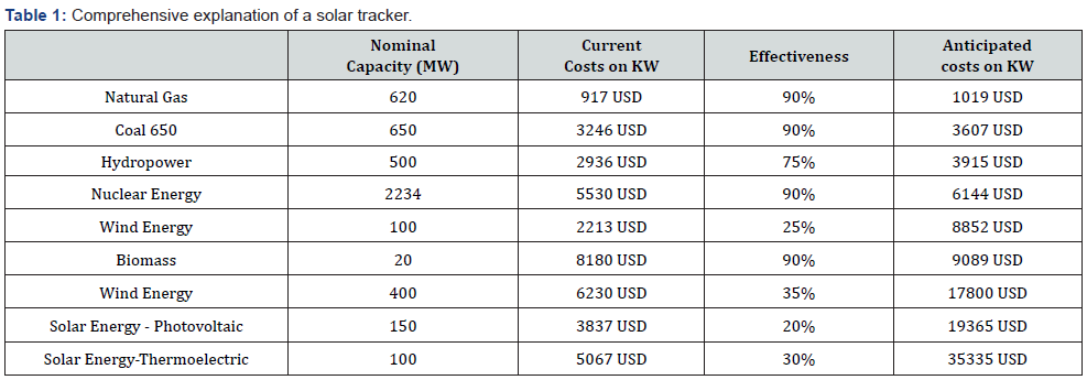
Several scholars have done reputable research on solar tracking systems and their importance in optimizing solar energy absorption from the sun. A solar tracker is described as a device to maximize solar energy captured from sunlight (77). The authors continue to explain that the device rotates in the sun’s direction to ensure that solar energy is continually absorbed throughout the day. The rises in the east and sets in the west and thus are found in different locations during the day. Static solar panels thus do not capture maximum solar energy as they do not move in the sun’s direction. However, the solar tracking devices that carry in the sun’s movement are more effective in capturing maximum solar energy. The two primary solar tracking devices are single- and dual-axis trackers [2]. We are given a comprehensive explanation of a solar tracker and how it works (Table 1).
Anuraj & Gandhi [3] explain the concept of light-dependent resistors (LDRs), microcontrollers, and step motors in a solar tracker. They are used to rotate the solar panels when a change in sunlight position is detected (563). Two LDRs on a solar tracker are stable when receiving the same light intensity. However, the light intensity on both LDRs changes when the sun moves, which is translated into voltage using voltage dividers. A comparator in the microcontroller is used to compare voltage, and a motor is used to control the solar panel in the direction of the sunlight.
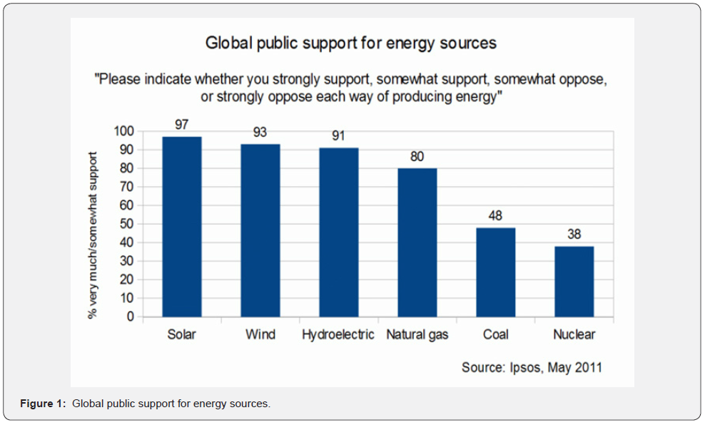
Mohana priya et al. [ 4] also explain that the software used controls the tilt point of the solar panel vertically and horizontally, which allows the solar panel to tilt according to the sun’s direction (2). Thus, remarkable research has been done on solar trackers and their work. Still, there is a gap in the use of radiation and altitude angle in improving solar panels, as most studies focus on just using the sun’s direction to optimize the system (Figure 1).
This paper will use our tracking technology to optimize the solar system based on radiation and altitude angle, rather than only the sun’s direction. Using a microcontroller, we will move the solar panel employing the LDR (light-dependent resistor). Using our proposed system, we’ll save more time by redirecting power from drained batteries to those that still need charging from the same solar panel that receives the most radiation.
Problem Identification
Climate change is a constant and persistent problem in our ecosystem. It is a growing illness that is being felt worldwide due to the increased growth and emergence of industries. Due to the effects of industrialization and consequent climate change, there is a need to find cleaner and more green ways to power cities and industries.
The effects are not only being felt by citizens themselves, but many organizations and governments have been keen to reduce the effects of pollution and curb it all together in an effort to conserve the environment (Jain et al.). Many rural areas often lack access to electricity; the locals are often located in marginalized areas where it would prove too costly to get power. There is a need to adapt to energy sources that will be better for them cost-wise as well as accessibility-wise.
The proposed approach to this is natural and surplus in nature, solar energy. In terms of affordability, it is free; which makes it much more accessible when placed in comparison to fossil fuels; which are mostly known due to their widespread usage. For example, petroleum products and Natural gas are the go-to energy sources in many parts of the world [2]. This suits the use of solar energy, especially in rural areas as well as marginalized and underdeveloped areas.
The need to utilize solar energy becomes apparent hence the question of how to maximize solar energy and generate power even if it’s cloudy or dusty. In these conditions, getting power as an energy source requires designing a robust system that can adapt to these conditions. By creating a solar tracking system, you could get the maximum capacity at any given time of day and coupling the system together with a storage system makes the system flexible. Thus, a battery solar tracking system solves the problem of getting the power required.
Developing the System
Specification Strategy
A lot of work has been put forward by scholars to sensitize the use of solar tracking systems and how important they can be when implementing a solar energy absorption system. A solar tracker, put simply, works by maximizing the amount of solar energy captured from the best solar source; the sun [2]. Their implementation describes the motion of the sun directly influences how the device operates. The solar tracker rotates in the same way that the sun does; that way there is continuous energy absorption throughout the entire day. This means that cloud cover is accounted for as one of the obstacles to preventing maximum energy absorption. Just as the sun rises and sets in the East and West respectively; so, does the solar tracker operate. This way it is locationally dynamicist’s location changes throughout different times of the day. As explained above, this would prove that solar trackers are much more efficient compared to solar panels which are static. Being static in nature means that they are unable to capture maximum solar energy due to their immobility with context to the sun’s motion as the earth rotates around as we switch between day and night. This means that solar trackers are much more effective in the absorption of solar energy due to their approach to implementation. They maximize the amount of solar energy drawn from the sun. There exist two main implementation types of solar tracking devices; namely single-axis solar trackers and dual-axis solar trackers [2]. We can follow either of the two to implement a working solar tracker.
Microcontrollers, step motors, and light-dependent resistors (LDRs) are what make up a solar tracker. These concepts work together to build a functioning solar tracker. They work by facilitating the rotation of the solar panels; the microcontrollers detect the motion of the sun, and these changes in the sun’s position are what determine the rotation of the solar panels [3]. We can do this by implementing two Light Dependent Resistors on a single solar tracker that works by stabilizing each other when they are hit with similar light intensity.
It works by changing the light intensity on both LDRs when a change in the sun’s position is detected, which is then used by voltage dividers and translated to voltage. Then a device known as a comparator within the microcontroller, is what is used to compare voltage between the two Light Dependent Resistors. In addition, a motor powers the motion of the solar panel in whichever direction sunlight is coming from [4].
The product utilizes software to control the tilting point of the solar panel that captures sunlight, either horizontally or vertically thereby making the required adjustments to capture the energy coming from the sun. By allowing a motion to be both vertical and horizontal, tilt can happen i.e., diagonal positioning for maximum sunlight exposure. Continuous and incremental research is still being done on solar trackers to maximize their efficiency. Some parameters such as the use of altitude angle of the terrain as well as radiation angle still offer a gap to improve the functionality of solar panels as most research is mainly focused on the direction and movement of the sun when optimizing solar panels.
In our system, our focus shall be optimizing solar tracking functionality using altitude and radiation angle technologies to build on existing studies that have worked on optimal solutions by just using the position of the sun as the determining factor of solar energy absorption. As discussed above the implementation will utilize microcontrollers and Light Dependent Resistors which will be embedded in the solar panels to manipulate their movement to maximize solar energy capture. The final system will be able to achieve much more peak power when the battery used to store energy is charged. This will conserve more time thereby building upon the efficiency of our system.
Designing the System
System Approximation and Sizing
Suwadirah: Our geographic Location (Saudi Arabia)
The location of our solar tracker influences the geographic conditions experienced. Solar Insolation is defined as the amount of power experienced in a cross-sectional area for a specified period of time. For our location, this is measured for 2700 hours in a period spanning a year. The average amount calculated for the period is 6.0kW/m2. The second measure we need is the estimation of the tilt angle every year which is given as 32.7 degrees Celsius [5].
Load Distribution and Calculation
The values in the table below are obtained from approximations of each of the consumptions of the loads as well as their respective distributions (Table 2). From the table above, we can see that we utilize a battery when night falls or when solar panels produce less power; hence a battery capacity of more than the loads is needed to achieve this.
Size of the system with Linear Programming
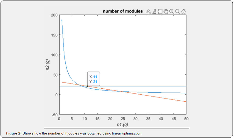
The load consumption is 84.5 kW; hence PV system is required to produce more than this. Consequently, PV capacity is estimated to be more than 100KW. The PV system will use mono crystalline solar panels with a nominal rating of 290Wp. The battery backup comprises 30 Lead-Acid batteries rated 24V and 300Ah.

The size of the system can be estimated using linear optimization whereby the power needed is given by p = pmaxn1n2 − 6(n1 + n2 ) but pmax = 640w .
Hence power equation for the system becomes

where n1 and n2 are the numbers of modules in series and parallel, respectively.
The constraints of the system are
640n1n2 >100000W , the minimum power required to sufficiently sustain the load.
 The maximum size of the panels in the grid
And n2 ≥ 21 since the minimum output voltage of the PV system
is given by  Hence graphical analysis of linear optimization whereby the result given by graph and equation 1 is
p = 640× 21×11− 6(11+ 21) =147KW n1 =11 and n2 = 21.
(Figure 2) below shows how the number of modules was obtained using linear optimization.
Designing The PV System
To produce consistent dc output, a controller is needed. The system utilizes a boost converter controlled by a pi controller and maximum power point software.
Boost Converter specification
The voltage output is 1000v, and the power output is 160 KW; hence the table below shows the parameters for the required system (Table 3).

Pi Controller
The formulae  gives the transfer function of a pi Controller. Here the value ‘s’ represents the time interval. We use
the Ziegler-Nichols Tuning method to obtain the values for both
Kp and Ki (Deželak et al. 2021). Overshoot and undershoot values
both decrease up to a desired limit from where the system is now
considered stable. The overall system is observed as a closed-loop
loop system.
The overshoot or undershoot decreases to an acceptable limit, and the system becomes stable in a closed loop.
Calculating the Maximum Power Point
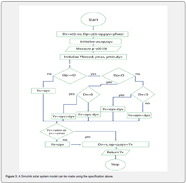
We need to determine the maximum efficiency achieved by our system. We do this by first achieving maximum power in our solar panels as a result of solar irradiation. We can obtain these values using a choice of algorithms to determine the maximum power observed. In our design, we utilize Perturb and Observe algorithm to get full power. It is a simple, yet powerful algorithm and it has the advantage of being easy to comprehend and develop [6]. A Simulink solar system model can be made using the specification above (Figure 3).
Battery
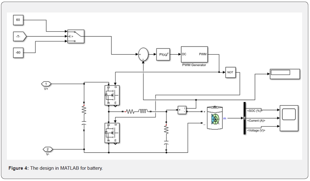
We can use a Simulink model that simulates the same effects as a real-world battery by specifying some control values. The battery capacity of 700v and 300ah power the system, and a pi controller is used in charging where the circuit behaves as a buck converter and boost Converter during discharging (Table 4). The design in Matlab is shown below (Figure 4).

Inverter
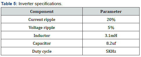
An inverter is required in the system to produce ac power for the loads; hence the inverter needs to make 220v ac at 50 Hz and deliver power up to 50Kw [7-9].
Input voltage is more significant than 700v (Table 5).
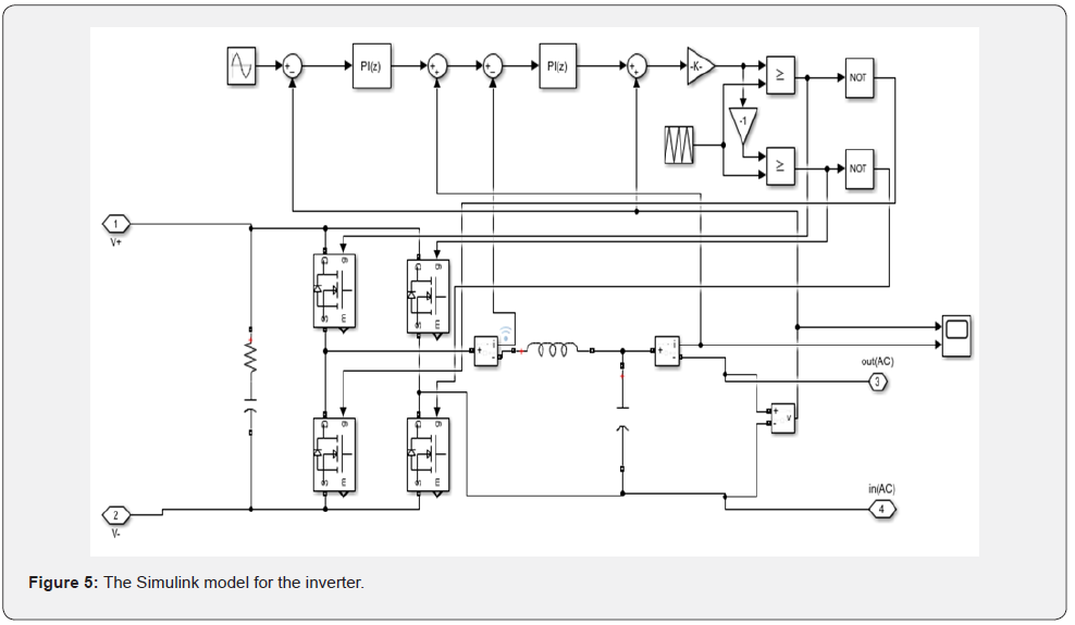
The Simulink model for the inverter is shown below (Figure 5).
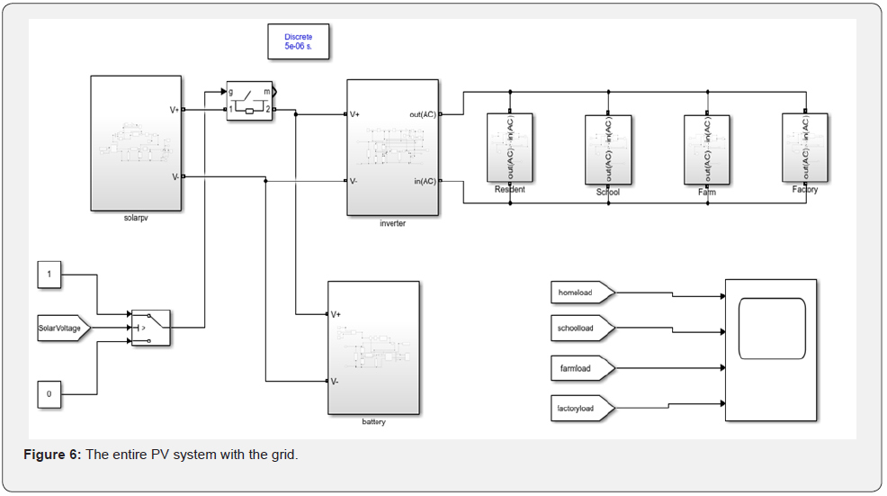
The entire PV system with the grid is shown below (Figure 6).
Designing the Tracking System
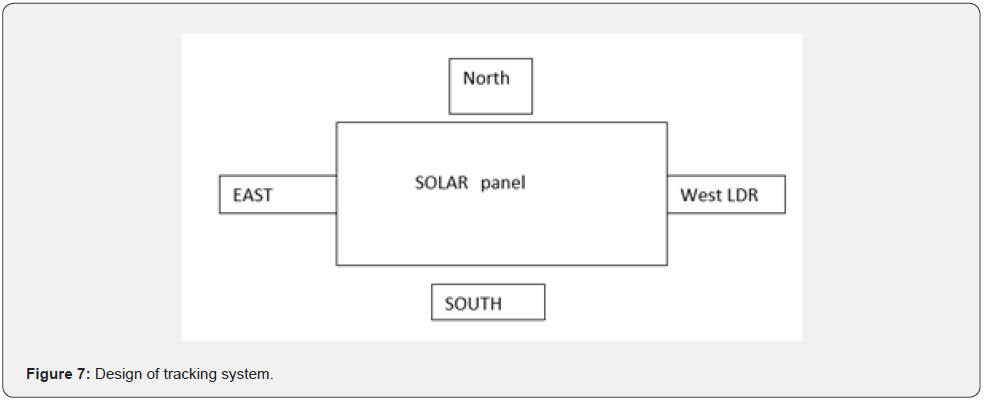
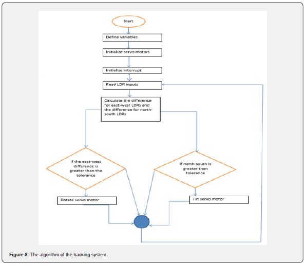
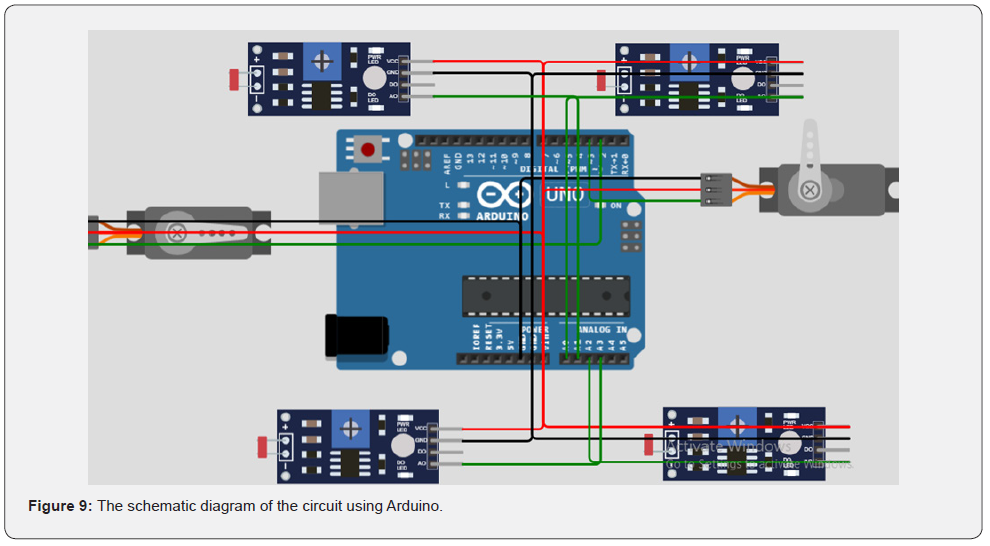
A dual-axis solar tracking system uses an Arduino board, LDRs, and servo motors. For a stationary solar panel, the loss in power is exceptional at 7 am in the morning and 6 pm in the evening(Alktranee, Al-Yasiri, and Sahib 2020). This results in the dual-axis tracker ensuring the solar panel faces these directions. Using four LDRs and Two servo motors, the solar panel can be moved in the correct direction [10-15]. By placing the LDRs as shown in the (Figure 7) below, the solar panel is controlled to tilt from north to south by a servo motor when the north LDR receives less light than the south LDR until the difference is tolerable, and also the solar panel rotates from east to west at particular tilt angle using the second servo motor. When east LDRs are less than west LDRs, it indicates movement from east to west to position the sun. This action enables the panel to be correctly set (Figure 7) [16]. The algorithm of the tracking system can be given as (Figure 8) [17]. The schematic diagram of the circuit using Arduino is shown below (Figure 9) [18].
Power Data Acquisition
The data acquired can be obtained from the solar irradiation curve of the given location. Using the formulae in solar time and angle calculator (Prof. Thomas Jenkins, Gabriel Bolivar) [19-23]. isolation =1000×(cosβ cos(−ρ )sinγ + sinβ cosγ ) Where β the elevation angle of the sun, ρ is the azimuth angle of the panel, γ is the tilt angle of the panel. The curve above is used to generate power for the specified PV module [24,25]. The output power is measured using voltage and current measuring devices and can be simulated using Simulink (Figures 10 & 11) [26].
Project Results
Comparison of the stationary PV system and PV solar tracking system
The graph below shows the power output of the stationary PV system [27]. In the stationary PV module, the sun irradiation is maximum around the periods around noon since the sun will be overhead the solar panel hence the panel generates a peak power value at this time hence describe the curve below shows the power increases at around noon (Figure 12) [28-30].
The graph below shows the power output of the PV solar tracking system [31]. For solar tracking systems, the power generated is consistent as the tracking system tries to point the solar panel to the sun at any given time hence the as the tracker pinpoints the solar panel at the sun irradiation the panel generates a consistent power that is around 80kw [32-34] as seen in the graph below hence the solar power generated is maintained at a certain level. Hence a linear kind of graph is generated (Figure 13).


Comparing the (Figures 12 & 13) above, it can be seen that the PV solar tracker outputs more power compared to the stationary system. This enables a maximum amount of energy for small space availability [35]. The table below shows the characteristics of the two systems above (Table 6). The results of the PV system can be seen when loading the data below, showing the state of the battery compared to the solar panel’s power output. The (Figure 14) below shows the voltage output of PV [36]. The voltage peaks as the system tries to stabilize the surge in energy generation and stabilizes to produce a consistent output voltage from the MPPT system (Figure 14).


Battery soc.
(Figure 15)The battery is used in the system to store energy produced by the PV system hence it is used for power when there is solar downtime and unfavorable weather. The battery is discharged when the power required by the loads is more than the power generated hence this design enables the loads to be provided with power whenever needed [37,38]. The graph above shows how the battery discharges when the solar system power produced is less. The solar PV system incorporates a flexible design to ensure the power produced is utilized and not wasted. The results prove that the tracking system is more efficient than the stationary solar system [39,40].
Conclusion
Electricity is becoming almost a basic need with the growth and development of the world. About 13% of the world’s population has no electricity. A solar tracking system has been introduced to allow for maximum capture of solar energy from sunlight, especially in rural areas where sunlight is inadequate. In our design, we were able to successfully implement and extend a dual-axis solar tracker. It consists of components that include two stepper motors, a set of servo motors, four static LDR sensors and finally an Arduino microcontroller that is used to evaluate the functionality of the system.
The results indicate that the system can track solar radiation direction with an error of 1.50 degrees in the rotation direction and 0.59 degrees in tilting. Using a dual-axis solar tracker system is feasible for solar panels with a capacity of 640Wp and above. The system is still able to produce power from the batteries in dark times and hence a consistent power supply is established for the loads as long as the system is active. The solar PV system is designed to be adaptable so that the generated energy may be put to good use. Compared to a fixed solar array, the data show that the tracking technology is much more effective.

References
- Mothilal Bhagavathy S, Pillai G (2018) PV microgrid design for rural electrification. Designs 2(3): 33.
- Sujatha B, Rani B, Ramya S (2018) Optimization and performance analysis of single axis solar tracker using matlab/simulink software. IJNRD-International Journal of Novel Research and Development, IJNRD 3(4): 77-81.
- Anuraj A, Gandhi R (2014) Solar tracking system using stepper motor. international journal of electronic and electrical engineering 7(6): 561-566.
- Mohanapriya V, Manimegalai V, Praveenkumar V, Sakthivel P (2021) Implementation of Dual Axis Solar Tracking System. In IOP Conference Series: Materials Science and Engineering 1084(1).
- Zewail MS, Dabour SM, Mansour DA, Rashad EM (2019) Carrier-based PWM Techniques for Current-fed Qua-si-Z-Source Converters. 2019 21st International Middle East Power Systems Conference, MEPCON pp. 1230-1234.
- Adil SM, Talib EH (2019) Designing a maximum power point tracking system for a monocrystalline silicon solar module using the Arduino microcontroller and synchronous Buck converter. FME Transactions 47: 524-533.
- Nasir S (2017) Introduction to Multilevel Inverters - The Engineering Projects. The Engineering Projects.
- Arulmurugan R (2020) Optimization of Perturb and Observe Based Fuzzy Logic MPPT Controller for Independent PV Solar System. Wseas Transactions on Systems 19:159-167.
- Atri PK, Modi PS, Gujar NS (2020) Comparison of Different MPPT Control Strategies for Solar Charge Controller. 2020 International Conference on Power Electronics & IoT Applications in Renewable Energy and its Control, PARC: 65-69.
- Awale KS, Kumbhar A, Kole VA, Kamate JB (2017) Arduino Based MPPT Solar Charge Controller. Journal of Electrical & Electronic Systems 6(2).
- Ban H, Lee J, Mok H, Choe G (2001) Load sharing improvement in parallel-operated lead acid batteries. ISIE 2001. 2001 IEEE International Symposium on Industrial Electronics Proceedings (Cat. No.01TH8570) 2: 1026-1031.
- Belarbi M, Kacher A, Hallouz Z (2019) Operating limits of battery charge controllers. 2019 8th International Conference on Renewable Energy Research and Applications (ICRERA) pp. 749-754.
- Burke RB, Henderson MI, Platts JE (2003) Load response and system reliability situations. In 2003 IEEE Power Engineering Society General Meeting 4: 2285-2288.
- Cabrane Z, Ouassaid M, Maaroufi M (2017) Battery and supercapacitor for photovoltaic energy storage: a fuzzy logic management. Iet Renewable Power Generation, 11(8): 1157-1165.
- Chassin DP (2004) Statistical mechanics: A possible model for market-based electric power control. In 37th Annual Hawaii International Conference on System Sciences pp. 10.
- Chatterjee A, Bhaumik S, Naskar A, Mondal N, Chatterjee D et al. (2020) A Transformer-less Grid Interactive Converter Topology for PV based Micro Generator. 2020 IEEE Calcutta Conference (CALCON) pp. 497-501.
- Covino S (2003) Demand side response 21/sup st/century style. In 2003 IEEE Power Engineering Society General Meeting (IEEE Cat. No. 03CH37491) 4: 2280-2284.
- Elavarasan RM, Shafiullah GM, Raju K, Mudgal V, Arif MT et al. (2020) COVID-19: Impact analysis and recommendations for power sector operation. Applied Energy 279: 115739.
- Erdinc O, Vural B, Uzunoglu M (2009) A dynamic lithium-ion battery model considering the effects of temperature and capacity fading. In 2009 International Conference on Clean Electrical Power pp. 383-386.
- Venkateshwarlu K, Premi MSG (2021) Renewable Energy Fed Bidirectional Converter Based on Grid Application Using Fuzzy Logic-PID Controller 12(6): 275-280.
- Han-Sik Ban, Jeong-min Lee, H Mok (2001) Hybrid modeling and control for a platoon maneuvers. ISIE 2001. 2001 IEEE International Symposium on Industrial Electronics Proceedings (Cat. No.01TH8570).
- Harwood RC, Manoranjan V, Edwards DB (2011) Lead-Acid Battery Model Under Discharge with a Fast-Splitting Method. IEEE Transactions on Energy Conversion 26(4):1109-1117.
- He Z, Yang G, Chen Y, Lu L, Wang Z et al. (2014) A battery modeling method based on percentage of discharge (POD). 2014 IEEE 23rd International Symposium on Industrial Electronics (ISIE) pp. 1754-1759.
- Hickok K (2021) What is a pandemic? livescience.com.
- Hiwale DA, Patil MV, Vinchurkar H (2014) An Efficient MPPT Solar Charge Controller. International Journal of Advanced Research in Electrical, Electronics and Instrumentation Energy 3(7): 10505-10511.
- Kehler JH (2003) Considerations for load as a virtual generator for grid security. In 2003 IEEE Power Engineering Society General Meeting (IEEE Cat. No. 03CH37491) 4: 2289-2292.
- Khateb AH, Rahim NA, Selvaraj J, Uddin MN (2014) Fuzzy-Logic-Controller-Based SEPIC Converter for Maximum Power Point Tracking. IEEE Transactions on Industry Applications 50(4): 2349-2358.
- Lawrence DJ, Neenan BF (2003) The status of demand response in New York. In 2003 IEEE Power Engineering Society General Meeting (IEEE Cat. No. 03CH37491) 4: 2270-2274.
- Malekjamshidi Z, Jafari M (2009) Design, Simulation and Implementation of an Intelligent Battery Charging System. 2009 Second International Conference on Computer and Electrical Engineering 2: 242-246.
- Mekhilef S, Faramarzi S, Saidur R, Salam Z (2013) The application of solar technologies for sustainable development of agricultural sector. Renewable & Sustainable Energy Reviews 18: 583-594.
- Mohod RR, Pawar MV, Pawar SH (2019) A Simulink Model for Three Switch Single Phase Switched Coupled Inductor Inverter for PV System. 2019 IEEE 5th International Conference for Convergence in Technology (I2CT) pp. 1-4.
- Mora J, Amaya D (2018) Modelling and Simulation of a Photovoltaic Solar System with Lead-Acid Battery. International Journal of Applied Engineering Research 13(16):12827-12831.
- Oliveira DQ, Saavedra OR, Santos-Pereira K, Pereira JD, Cosme DL (2021) A critical review of energy storage technologies for microgrids. Energy Systems.
- Rovnyak SM, Mei K, Li G (2003) Fast load shedding for angle stability control. In 2003 IEEE Power Engineering Society General Meeting (IEEE Cat. No. 03CH37491) 4: 2275-2279.
- gov: USA. gov for Science - Government Science Portal. Science. gov. (2022).
- Selmani A, Ed-dahhak A, Outanoute M, Lachhab A, Guerbaoui M et al. (2016) Performance Evaluation of Modelling and Simulation of Lead Acid Batteries for Photovoltaic Applications. International Journal of Power Electronics and Drive Systems 7(2): 472-480.
- Sinkaram C, Asirvadam VS, Nursyarizal Bin Mohd Nor, Begam MJ (2012) Battery characteristics due to various discharging current and temperatures: A simulation approach. 2012 IEEE Student Conference on Research and Development (SCOReD) pp. 22-27.
- Treptow RS (2002) The Lead-Acid Battery: Its Voltage in Theory and in Practice. Journal of Chemical Education 79:334-338.
- Yang S, Peng FZ, Lei Q, Inoshita R, Qian Z (2009) Current-fed quasi-Z-source inverter with voltage buck-boost and regeneration capability. 2009 IEEE Energy Conversion Congress and Exposition pp. 3675-3682.
- Zhang D, Hu M, Ji Q (2020). Financial markets under the global pandemic of COVID-19. Finance research letters 36: 101528.


