


Design Trade-Offs and Challenges on Miniaturized Antenna for Bluetooth in Internet of Things Applications
Steve WY Mung1,2*, Ka Ming Wu1 and Joseph SM Yuen1
1Innovation Technology Co Ltd, Hong Kong
2Department of Electronic and Information Engineering, The Hong Kong Polytechnic University, Hong Kong
Submission: June 17, 2019; Published: June 26, 2019
*Corresponding author:Steve WY Mung, Department of Electronic and Information Engineering, The Hong Kong Polytechnic University, Hong Kong
How to cite this article:Steve WY Mung, Ka Ming Wu, Joseph SM Yuen. Design Trade-Offs and Challenges on Miniaturized Antenna for Bluetooth in Internet of Things Applications. Eng Technol Open Acc. 2019; 3(1): 555602. DOI: 10.19080/ETOAJ.2019.02.555602
Abstract
This article focuses on miniaturized antenna for Bluetooth in Internet of Things (IoT) applications. Dielectric and printed circuit board (PCB) antennas are commonly used in the Bluetooth applications under 2.4GHz industrial, scientific, and medical (ISM) band. Bluetooth Low Energy (BLE) technology is one of the suitable platforms and technology for IoT applications under this ISM band. Antenna is typically occupied one-third size of overall circuit; therefore, a small, low profile and low-cost antenna is a good advantage for the commercial and medical applications. In this article, miniaturized antennas have their pros and cons in its performance and applications were presented as well as the design trade-offs and challenges on dielectric and PCB antennas for Bluetooth in IoTs applications were reviewed.
Keywords: Internet of Things (IoT); Meandering line; Antennas; Dielectric antenna; band
Abbreviations: BLE: Bluetooth Low Energy; ISM: Industrial Scientific and Medical; PCB: Printed Circuit Board; LTCC: Low temperature Co-Fired Ceramic
Introduction
The Bluetooth Special Interest Group (SIG) was formed with five companies in 1998, [1] in order to develop a new wireless standard for communication between mobile devices. Bluetooth technology uses the adaptive frequency hopping to minimize interference from other technologies in the 2.4GHz industrial, scientific, and medical (ISM) band. First chip was developed to integrate radio frequency, baseband, microprocessor functions and Bluetooth wireless software for mobile headset application and different modules were then developed later [2,3]. New Bluetooth versions and different profiles were then come out for different applications such as mobile headset [4], music streaming [5], data transfer [6]. Internet of things (IoT) applies current technologies to connect to the internet to improve different industries and environment for a higher quality of life in society by convey information to different users or applications. There are different wireless solutions for these IoT applications [7,8], however, Bluetooth Low Energy wireless technology, (BLE) [1] is one of the best choices of the IoT applications, which was released in Bluetooth Core Specification Version 4.0 in 2011. BLE is an excellent solution for a great variety of applications such as the medical e-health applications [9], positioning system [10] and monitoring system [11]. There are different chipsets or modules for BLE applications, which include antenna and RF front-end circuits as well as baseband processor. Nowadays, the size and the current consumption are indicators of research area and the size of antenna is one of the main challenging research areas.
Dipole antenna [12] is the simplest class of antenna in wireless application. In Figure 1, dipole consists of two identical conductive elements into which radio frequency current flows. This current causes signal radiation through the dipole. Dipole, theoretically, is required its length to be half wavelength (0.5λ) for maximum response [12]. A half wavelength corresponds to approximately 6cm (in air) in the 2.4GHz ISM band. In Figure 2, the ground plane acts as a good radiator [13] which helps the length of antenna become quarter-wavelength long. However, the position and size of the ground plane are very important in the design since the field (above the ground) is the same as if the ground is replaced by a mirror image of the antenna shown in Figure 2(b). The current in the reflected image has the same direction and phase that the current in the real antenna. This quarter-wave plus this image forms a half-wave dipole when the ground plane is infinite or very much larger in its dimensions than the half wavelength itself. In the real application, this quarter-wavelength antenna still occupies one-third size of overall wireless part. If the ground plane is significantly smaller than quarter-wave, antenna tuning becomes difficult and the overall radiation performance is degraded. The active antenna measurement of the complete products [14] such as the overthe- air (OTA) performance is more precise to predict or indicate the power radiated or received compared to passive antenna measurement [15]. In small portable devices, dielectric and PCB antennas are commonly used in the Bluetooth applications, therefore, in this article, design trade-offs and challenges on these antennas for Bluetooth in IoTs applications were reviewed.


Design trade-offs and challenges on dielectric and PCB antenna
There are many size-reduced antennas solutions for 2.4GHz ISM band. In Figure 3(a), dielectric antenna is one of the common solutions and it is miniaturized by using Low Temperature Co- Fired Ceramic (LTCC) Technology [16-18]. LTCC has the ability to embed low and high dielectric constants inside the antenna. This enables antennas to have great detuning resilience and extreme temperature stability behavior. However, a trace (with length L) on a printed circuit board (PCB) as antenna in Figure 3(b) is also commonly used which is called PCB monopole antenna. PCB monopole antenna has its advantages of small, low-profile, and low cost compared to dielectric antenna. In Figure 3, the dielectric and PCB monopole antennas are shown with length L and they are called monopole antenna consisting of one half of a dipole antenna in Figure 2, and always mounted above the ground plane like Figure 2(b). The matching network at the input is for maximum power transfer [12]. The length used is onequarter of the wavelength (L = λ/4), so called a quarter-wave monopole antenna, therefore, the operation is same as dipole antenna because of the mirror image in Figure 2(b)

Effect on ground plane
All antennas, like other electronic component, have at least two connections for the signal feed. The antenna and the ground plane combine to form a complete circuit; therefore, the ground plane is part of antenna. The electromagnetic field is set up between the antenna and the ground plane, with current flowing through the field, therefore completing the circuit shown in Figure 4. In general, a ground plane is designed to spread out at least a quarter wavelength, or more to form the mirror image in Figure 2(b). A ground plane is also, ideally, made smaller, but it affects the performance of the antenna, therefore, the area of ground plane must be considered and has its size limitation. In passive antenna measurement, it was found that the cable from the equipment connected to the antenna plays an important role if antennas have a relatively small ground plane which makes it relatively easy for the current to go to the outside of the feed cable and radiate to contaminate the measurement [15]. The active antenna measurement [14] such as the over-the-air (OTA) performance is one of precise measurement to predict the overall performance compared to passive antenna measurement. Total radiated power (TRP) and total isotropic sensitivity (TIS) are measured in active antenna measurement to determine the performance of transmission and reception respectively.

Effect on length
Figure 5(a) shows an incident E-field (with wavelength equal to λ1) propagates to a vertical dipole of length L = 0.5λ1. If the current distribution of the dipole is uniform, the actual current distribution is nearly sinusoidal, [12]. However, if the same dipole is used at a longer wavelength, λ2 (λ2>λ1) so that length is only L = 0.1λ2 long compared to the incident E-field (with wavelength equal to λ2). The current tapers almost linearly from the central feed point to zero at the ends in a triangular distribution in Figure 5(b). Assuming dipole with uniform current distribution, the radiation resistance Rrad, in free space is given by [12]:

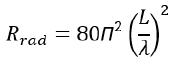
For triangular current distribution in Figure 5(b), the radiation resistance is smaller than those in Figure 5(a). Small values of radiation resistance indicate that the radiation of antenna is not very efficient. Antenna with shorter length but not resonant in the correct operating frequency leads to poor radiation since the resonant frequency is higher than the desired operating frequency. Additional matching network is required to return to the desired frequency. This matching network is used for maximum power transfer from the radio transceiver to antenna [12], however, the antenna still gives poor efficiency because of higher resonant frequency itself.
There are different sizes among the LTCC antenna in the market such as the length L with 7mm, 5mm and 3mm in Figure 3(a), [16,17], therefore, the shorter of LTCC antenna give smaller values of radiation resistance resulting worse radiated performance. The length L of PCB monopole antenna in Figure 3(b) sometimes used is not enough to one-quarter of the wavelength (L = λ/4) due to limited space, therefore, meandering line is used to increase its total length in Figure 6. Antennas with reactance loading [18-20] were also used to lower the resonant frequency due to the length is not enough as well, which appears electrically longer itself. The quality-factor, Q of the reactance affects the performance of the antenna.

Printed Inverted-F Antenna (PIFA) in Figure 7 is one of the widely used modified PCB monopole antenna in small portable devices [21-25]. It is having a shorting feed point along the main resonant structure shown. It has the advantage that this folded part introduces capacitance to the input impedance of the PIFA which is cancelled by the shorting feed point. This configuration, therefore, reduces the antenna size.

Results and Experimental Verification
Figure 8 shows the two dielectric antennas with 3mm in length, which is one of the smallest 2.4GHz ISM antennas in the market. In Figure 8, there is one antenna without any matching network and its resonant frequency is shown in Figure 9 which is around 2.84GHz. Same antenna but with matching network added at the input in Figure 9 shows that the resonant frequency is tuned back to 2.45GHz for maximum power transfer, which still give small radiation resistance as well as poor efficiency because of actual resonant frequency at 2.84GHz. In Figure 10, an additional strip at the end of 5mm antenna is used to fine tune the resonant frequency since there is little draft of resonant frequency due to the mechanical housing and PCB ground plane. This 5mm dielectric antenna in Figure 10 is if one-quarter of the wavelength of around 2.45GHz, in which the resonant frequency is shown at around 2.45GHz in Figure 11 compared to 3 mm antenna with matching network in Figure 8 & 10. The capacitiveloaded antenna is also shown in Figure 10 with two capacitors added to lower the resonant frequency, making it appear electrically longer and resonant frequency in 2.4GHz ISM band is shown in Figure 11. Traditional PIFA (PIFA1) was fabricated and measured shown in Figure 12 & 13, and the size of this PIFA1 is larger than that of meandering PIFA (PIFA2) in [25]. The measured S-parameter, S11 in Figure 13 shows that both PIFAs is operated in the 2.4GHz ISM band and it easily to fine tune as well by tuning the length of the line.


The radiation patterns of PIFA2 at 2.45GHz is shown in Figure 14. Table 1 shows the comparison table of these antennas. It shows that the dielectric antennas have a little size smaller than the PCB antennas (PIFA1 and PIFA2). However, PCB antennas were only fabricated on PCB, which is approximately zero in thickness as well as zero in the cost of antenna itself and matching components. The performance of PCB antenna is comparable to that of dielectric antennas.


Conclusion
In this article, design trade-offs and challenges on dielectric and PCB antennas for Bluetooth in IoT applications were reviewed. It shows minimizing the size of antenna in IoT applications by using different methods. The measurement results of return loss and gain performance were showed and compared that PCB antennas give better performance compared to the dielectric antennas and no extra components is used for good impedance matching resulting lower in the cost.
References
- https://www.bluetooth.com
- Cho YH, Hwang GM, Kim BG, Choi YH, Park YH (2008) Very compact LTCC transceiver for bluetooth systems. Asia-Pacific Microwave Conference (APMC).
- Rotaru M, Ying LY, Kuruveettil H, Rui Y, Chee PC, et al. (2008) Implementation of packaged integrated antenna with embedded front end for bluetooth applications. IEEE Trans Adv Packag 31(3): 558-567.
- Hermann D, Brennan RL, Sheikhzadeh H, Cornu E (2004) Low-power implementation of the Bluetooth subband audio codec. IEEE International Conference on Acoustics, Speech and Signal Processing.
- Khalifa OO, Khan S, Islam MDR, Muktar MB, Yaacob Z (2004) Speech coding for Bluetooth with CVSD algorithm. RF and Microwave Conference (IEEE Cat. No.04EX924).
- Razavi R, Fleury M, Chanbari M (2007) Adaptive packetisation for video streams for Bluetooth v.2.0 data rates. Electron Lett 43(4).
- Tabish R, Ben MA, Touati F, Ghaleb AM (2013) A comparative analysis of BLE and 6LoWPAN for U-HealthCare applications. 7th IEEE GCC Conference and Exhibition (GCC) pp. 286-291.
- Zhang Z, Hu X (2013) ZigBee based wireless sensor networks and their use in medical and health care domain. Seventh International Conference on Sensing Technology (ICST), pp. 756-761.
- Satija U, Ramkumar B, Sabarimalai MM (2017) Real-time signal quality-aware ECG telemetry system for IoT-based health care monitoring. IEEE Internet Things J 4(3): 815-823.
- Deng Z, Fu X, Wang H (2018) An IMU-Aided Body-Shadowing error compensation method for indoor Bluetooth positioning. Sensors 18(1): 304.
- Zanella A, Bui N, Castellani A, Vangelista L, Zorzi M (2002) Internet of things for smart cities. IEEE Internet Things J 1(1): 22-32.
- Kraus JD, Marhefka RJ (2002) Antennas: For all applications. McGraw-Hill.
- Holzman E (2006) Essentials of RF and microwave grounding. Artech House: Boston.
- Scannavini A, Foged LJ, Gross N, Noren P (2014) OTA measurement of wireless devices with single and multiple antennas in anechoic chamber. The 8th European Conference on Antennas and Propagation (EuCAP), pp. 3499-3595.
- Huang Y, Loh TH, Foged LJ, Lu Y, Boyes S, et al. (2010) Broadband antenna measurement comparisons. Proceedings of the Fourth European Conference on Antennas and Propagation.
- Seo D, Jeon S, Kang N, Ryu, J, Choi JH (2008) Design of a Novel Compact Antenna for a Bluetooth LTCC Module. Microw Opt Techn Lett 50(1): 180-183.
- Yeung LK, Wand J, Huang Y, Lee SC, Wu KL (2006) A Compact LTCC Bluetooth System Module with an Integrated Antenna. Int J RF Microw CAE 16(3): 238-244.
- Zhao A, Xue, J, Jing C, Salo A (2008) The use of Murata ceramic Bluetooth antenna for wrist device based on flexible printed circuit boards. European Conference on Wireless Technology, pp. 334-337.
- Tornatta P, Kinetics C, Jose S (2014) A Method to Design an Aperture-Tuned Antenna Using a MEMS Digital Variable Capacitor. Microw J.
- Rowell CR, Murch RD (1997) A capacitively loaded PIFA for compact mobile telephone handsets. IEEE Trans Antennas Propag 45(5): 837-842.
- Hristov HD, Carrasco H, Feick R (2008) Bent inverted-F antenna for WLAN units. Microw Opt Techn Lett 50(6):1505-1509.
- Ammann MJ, Doyle LE (2001) A loaded inverted-f antenna for mobile handsets. Microw Opt Techn Lett 28(4): 226-228.
- Palukuru VK, Pekonen A, Pynttari V, Makinen R, Makinen R, et al. (2009) An inkjet-printed inverted-F antenna for 2.4 Ghz wrist applications. Microw Opt Techn Lett 51(12): 2936-2938.
- Su, Saou Wen Su (2015) Linearly polarized patch PIFA for GPS/GLONASS operation for tablet-computer applications. Microw Opt Techn Lett 57(1): 149-153.
- Cheung CY, Yuen JSM, Mung SWY (2018) Miniaturized printed inverted-F antenna for internet of things: a design on PCB with a meandering line and shorting strip. International Journal of Antennas and Propagation Article ID 5172960.


