


Design and Analysis of Hafnia Bow-Tie Terahertz Antenna Detectors
Sai Dittakavi and Ibrahim M Abdel Motaleb*
Department of Electrical Engineering, Northern Illinois University, USA
Submission:October 27, 2018; Published: March 19, 2019
*Corresponding author:Ibrahim M. Abdel-Motaleb, Department of Electrical Engineering, Northern Illinois University, USA
How to cite this article: Sai D, Ibrahim M A M. Design and Analysis of Hafnia Bow-Tie Terahertz Antenna Detectors. Eng Technol Open Acc. 2019; 2(5): 555599. DOI: 10.19080/ETOAJ.2019.02.555599
Abstract
Terahertz sensors and antennas are used in applications ranging from space exploration to biomedical imaging. This study investigates he performance of Hafnium oxide (HfO2) based antennas, where HfO2 allows for the integration of antennas with optical devices, as well as ferroelectric memories. Antennas made using Gold/Hafnia (Au/HfO2) and Indium Tin Oxide/Hafnia (ITO/HfO2) have been designed and analyzed using the finite element, Multi-physics, COMSOL program. The study shows that the output electric field for the antennas using gold is almost 80% higher than the output field for those using ITO. However, ITO has the advantage of allowing for vertical integration with optical devices. The study investigated the effect of the antenna’s dimensions on the performance. The study found that the frequency at which the antenna resonates depends on the length of the antenna. Accordingly, integrating antennas with different lengths, narrow or wide band detectors arrays can be built. These sensors can also be integrated with hafnium based integrated circuits, memory cells, and other optical/optoelectronic devices.
Keywords: Bow-tie antenna; Terahertz antenna; Terahertz detectors; Terahertz-sensors
Introduction
Hafnia, or Hafnium oxide (HfO2) is a high dielectric material with very wide band gap. HfO2 is transparent to the entire spectrum of the visible light down to the UV and beyond [1]. This wide band gape allows for the integration of antennas with ferroelectric memories and optical/ optoelectronic devices. Hafnia has energy gap ranging from 5.1 to 5.99, depending on the material deposition [2,3]. The static dielectric constant for HfO2 varies from 16-70, depending on the lattice structure, whether it is cubic, tetragonal, or monoclinic structure [4].
The infrared range of the electromagnetic spectrum extends from 300GHz to 450THz, or from a wavelength of 1mm to 700nm. Part of this spectrum, which is a quasi-optical frequency, is called the Terahertz radiation or the terahertz gap, since it has unique characteristics. Terahertz radiation is normally defined as the electromagnetic spectrum that occupies the range from 0.3THz - 3THz. This range is also known as the sub-mm wave, since its wavelength falls between 1mm and 0.1mm [5,6]. This wavelength region is sandwiched between the micro-wave and the infra-red regions.
Terahertz (THz) spectrum offers many applications in science and engineering. Among these applications are space exploration, medical imaging, security, communications, scientific instrumentations, and military applications [5,6]. Terahertz spectrum can be used for molecular detection, since it allows for creating natural resonance unique to the specific atom or molecule [6]. One of the main advantages of THz radiation is its non-ionizing property. This property makes THz safe for use in medical applications, where tissues and DNA will be safe from damage.
The antennas used in this study are bow-tie antennas, where a bow-tie-shaped metal is deposited on top of dielectric substrates. The performance of these antennas is affected by the dielectric strength of the substrate [7]. Low dielectric substrates, such as silica, have been used to build THz antennas, and their performance have been reported in the literature [3,7-10]. Very high dielectric substrates, such Barium Strontium Titanate (BaSrTiO3), have been also used to build bow-tie antennas [7].
Gold is, normally, the metal of choice for building THz antennas. Gold is preferred because it has very high conductivity and are resistant to chemical reaction. On the other hand, gold is opaque to the optical spectrum. This limits the ability of gold to vertically integrate with optical/optoelectronic devices. To ensure integration with optical devices, transparent metals should be used. Indium-Tin-Oxide (ITO) can provide this advantage, since it is a transparent wide bandgap degenerate semiconductor with very high conductivity, where it can act as a metal.
Bow-tie antenna shape has been studied by many research groups [7,11-13]. Bow-tie antennas provide high output field. The field is measured across a nano-gap created between the two sharp points of the vertices, as shown in Figure 1a & 1b. The size of the tip is normally in the submicron, or nano, range. These sharp apices result in the creation of high density of charges due to the accumulation of electrons on the tips. This, in turn, enhances the value of the output field.
In this study, bow-tie nano-antennas made of Au and ITO on HfO2 substrates have been designed and analyzed. The analysis was made, using finite element numerical analysis, using COMSOL [4]. The range of the simulation was chosen to be in the 0.3-5THz range. The performance of any antenna depends on the properties of the substrate, the conducting metal, and the geometry. Therefore, the main focus of this study was to investigate the effect of the material properties and the dimensions of the antennas on the output signal.
Antenna Geometry
This antenna is basically two triangles with a nano-gap between their vertices, as shown in Figure 1. The dimensions of the antenna are 16μm length, 9μm width, and 1μm thickness. The gap is 100nm between the two apexes. COMSOL simulation of the antenna is shown in Figure 1b, where the highest field intensity is shown as a bright area across the gap. The metal is dim indicating that it has weak or zero field intensity.

The simulation geometry is shown in Figure 2. The figure shows that the antenna is placed on top of a 20μm HFO2 substrate. On the top of the antenna, a 20μm of air is placed. To avoid reflections from the top and the bottom boundaries, Perfectly Matched Layers (PML), with thickness of 10μm are used above the top air layer and under the dielectric layer [5,13]; see Figure 2. The PML’s are not boundary conditions but additional domains that absorb incident wave without producing reflections. The antenna is illuminated vertically by an Electromagnetic wave port with 1V/m magnitude in the z-direction. The port is excited with an electric source placed at 20μm above the antenna metal, just below the upper PML layer. The captured electric field across the gap is the output of the nano-antenna.

In COMSOL, Maxwell equation is used to obtain the electric field, which is
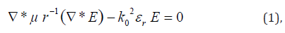
where E is the electric field, μr is the relative permeability, and εr is the relative dielectric constant, and k0 is the wave number = (ω/c), where ω is the radial frequency and c is the speed of light.
The gap between the two triangles of the bow-tie dipole antenna affects the performance of the antenna. The electric field is typically concentrated at gap of the antenna due to Coulomb field [13]. In this case, the gap acts as a capacitor, as shown in Figure 1b. The effect of the gap dimension on the antenna’s performance is investigated to obtain the optimum gap dimension, as it will be discussed later [14].
The dielectric constant for conducting materials is obtained from the Drude model, which is [15]:
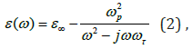
where ε_∞ represents the contribution of the bound electrons to the relative dielectric constant, τ ω is the damping frequency, and
 is the plasma frequency, where q is the charge of
an electron, n is the free electron density in the conduction band,
m* is the electron effective mass, and e0 is the permittivity
of the
free space.
is the plasma frequency, where q is the charge of
an electron, n is the free electron density in the conduction band,
m* is the electron effective mass, and e0 is the permittivity
of the
free space.
The dielectric parameters for conducting materials are complex values, since they are frequency dependent, as shown in Eq. (2). COMSOL uses Eq. (2) to obtain the complex dielectric values for the metals as a function of the frequency [16]. For insulators, the dielectric constants are real numbers and independent of the frequency. This is because plasma frequencies for dielectrics are very low, due to the low densities of conduction electrons.
Results and Discussion
To ensure that our simulation technique is correct, we started with the simulation of a reported Au/silica bow-tie antenna and compared our simulation results with the reported results published in Ref [5]. In this simulation, the conductivity of Au is taken to be 45.6x10⁶ S/m and the complex dielectric constant to be -8.49+1.62i. For silica the dielectric constant was assumed to be 2.03. The published results are shown in Figure 3a and our results are shown in Figure 3b. As can be seen from the figures, our simulation results are almost identical to the published results. The match between the two results provided the necessary evidence that our simulation technique is accurate.

After ensuring the accuracy of our simulation results, Au/HfO2 and ITO/ HfO2 antennas were designed and simulated. For Au, the conductivity and the dielectric constant, mentioned above, were used in the simulation. For HfO2, the dielectric constant was taken to be 25 [4]. For ITO, the conductivity was taken to be 1.3x10⁴ S/m, and the dielectric constant was taken to be 3.37+0.01i.
The dimensions of the base antenna are those shown in Figure 1. The dimensions are changed from the base dimensions and the effects of the change on the electric field have been studied. First, we change the gap separation to 100nm, 200nm, 300nm, 400 nm, and 500nm, while all other dimensions remained the same. The output field was simulated with the different values of the gap size mentioned above.
The results for the Au antennas are shown in Figure 4a, while the results for the ITO are shown in Figure 4b. The figures show that there are several peaks at different values of resonant frequencies. In this case the peaks take-place at 1THz, 2THz, 3THz, and 4THz, for both sets of antennas. This means the resonant frequencies are independent of the gap size.

The figures show also that the electric field decreases as the gap dimension increases. This can be explained from the coulomb effect, or the capacitance behavior. The electric field between the two plates of a capacitance increases as the separation between the plates decreases, assuming that the charges on the plates remain constant. The same effect takes place across the gap. This means that the gap should be as small as possible to increase the output field to the highest possible value. In other words, we should have the smallest gap separation, which can only be determined by the fabrication technology used. The figures show also that the output from the Au antennas are higher than that of ITO antennas by at least 80%. This can be attributed to the high conductivity of Au which is 45.6x10⁶S/m compared to only 1.3x10⁴S/m for ITO. This behavior is noticed in all simulation, since it is related to the metal conductivity, not to the antennas’ dimensions.
The figures show also that, for Au antennas, the peak at 1THz is lower than the peak at 3THz; while for ITO, the 1THz peak is higher than the 3THz one. This difference is a result of the solution of Maxwell equation and not related to the material or the dimensions of the antennas.
Figure 4. shows also that for each antenna there are one fundamental peak and several secondary peaks. The highest peak is the fundamental peak with the main resonant frequency. The main resonant frequency, or the fundamental frequency, f0, can be obtained from the equation [17]:
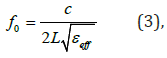
where, c is the speed of light, L is the length of the antenna and eff ε is the effective dielectric constant at f0. Because of the periodic nature of the geometry of the antenna, not only the antenna resonates at the fundamental frequency, it resonates at secondary frequencies. Resonance takes place at … f0/n, f0, n f0, … where n is an integer. Our results are in agreement with this statement. As shown in Figure 4, the antennas resonate at a fundamental frequency of about 2THz, but also at the secondary frequencies of 1THz, 3THz, and 4THz. According to Eq. 3, f0=1.9 THz, which is very close to the 2THz obtained from COMSOL simulation.
The resonant frequency depends also on the substrate (insulator) dielectric constant. From Eq. 3, it is clear that substrates with higher dielectric constant will exhibit low fundamental resonant frequencies. Using Eq. 3, an antenna of Au/silica should have a resonant frequency of 6.58 THz. However, a secondary peak for n=2 could appear at f0/n= 3.29 THz, which is the value shown in Figure 3.
The fundamental frequency did not show in the simulation, because our simulation range is from 0.3-5 THz. Similarly, as reported in reference [7], when Barium Strontium Titanate (BaSr- TiO3) was used, the fundamental frequency decreased. In this case, according to Eq. 3, f0= 0.54 THz, which is confirmed by COMSOL simulation [7]. Hence, the resonant frequency can, not only be controlled by the antenna length, but also by the type of the insulating substrate.
Next, the gap size was fixed to 100 nm, and the metal thickness changed to the 0.2μm, 0.5μm, 1μm, 2μm, and to 5 μm. The results for the output field for these antennas are shown in Figure 5a & 5b, for the Au and ITO, respectively. The figures show that for both the Au and ITO antennas, the higher the thickness the higher the output field is. We figured out that either the skin depth or the metal conductivity is responsible for the observed behavior. However, when the skin depth was calculated for the metals, it was found that it did not exceed 70nm. Since the minimum thickness of the metal used is 0.2μm, it is believed that the change in the output field is not affected by the skin depth. Therefore, it has been concluded that the metal thickness is responsible for the output field change. As the meal thickness increases, the conductivity increases, and the electrons generated due to the wave absorption find it easier to move to the gap to contribute to the increase of the electric field. For this reason, Au antennas generate higher output field than ITO antennas, as a result of the high conductivity of Au.

Figure 6a & 6b show the effect of the change of the width of the antenna on the output electric field. Antennas with widths of 2μm, 4μm, 8μm, 10μm, and 12μm are simulated. As can be seen from the figures, the width value has little effect on the output field, with only a maximum change of less than 10%.
It should be noted that only the dimension that is along the incident field will affect its corresponding output; while the perpendicular dimension will not affect it. In our simulation, the incident electric field is aligned along the length, while the magnetic field is aligned along the width. Accordingly, it is expected that the length will affect the output electric field and the width shall affect the output magnetic field only. Consequently, the output electric field should be invariant with the width, since the electric field is perpendicular to the width, and this is what Figures 6a & 6b are showing.

The effect of the length of the output were investigation, and the results are shown in Figure 7. In Figure 7, the fundamental frequency was found to change with the length; while in Figures 4 to 6, the fundamental frequency remained constant at 2THz. This is expected, since according to equation (3), the resonant frequency depends on the length of the antenna. Since in Figures 4-6, the length remained constant at 16 μm, f0 remained constant at 2THz. Figure 7 shows that f0 is 1THz for L=20μm, 2THz for L=16μm, 3 THz for L=12μm, and 4THz for L= 8μm. For L=25, there are several small peaks the smallest one is the fundamental frequency. It should be noted that f0 decreases with the length, since f0 is proportional to 1/L, as shown in Eq. 3. As revealed in Figures 4-6, Figure 7a & 7b show that the output for Au antennas are about 80% higher than the output for ITO antennas.

As explained above, the reason that the output is affected by the length is because the incident electric field is applied parallel to the length. If the incident electric field was applied parallel to the width, the output would not have been affected by the length. Instead, it would have been affected by the width. This explanation supports the fact that the width does not have any impact on the output.
Conclusion
In conclusion, bow-tie antennas using Hafnium oxide have been designed and analyzed using the Multiphysics, finite elements package, COMSOL. The study revealed how the output field depends on the antenna’s dimensions, the metal conductivity, and the substrate material. The results from this study provided a road map on how to optimize the performance of the antenna with respect to the gap size, length, width, and thickness. The results also show that using substrates with higher dielectric constant will result in lowering the fundamental resonant frequencies. Using the length and the type of substrate, a THz antenna array for narrow band detection at specific frequency can be built. On the other hand, by building an array that combines antennas with different lengths, a THz wide band detector can be realized. Since hundreds of thousands of bow-tie antennas can be fabricated on a 4-inch wafer, one can build cost effective, high output wide band detectors, as well as narrow band detectors.
References
- Kuhaili MF Al (2004) Optical properties of hafnium oxide thin films and their application in energy-efficient windows, Optical Materal 27(3): 383-387.
- Khoshman JM, Khan A, Kordesch ME (2008) Amorphous hafnium oxide thin films for antireflection optical coatings, Elsevier, Surface and Coating Technology 202(11): 2500-2502.
- Venkatachalam Jayaraman, Suresh Sagadevan, Rajesh Sudhakar (2017) Studies on Optical and Electrical Properties of Hafnium Oxide Nanoparticles. Journal of Electronic Materials, p. 7.
- Xinyuan Zhao, David Vanderbilt (2002) First-principles study of structural, vibrational, and lattice dielectric properties of hafnium oxide” Physical Review B 65: 233106-1-233106-4.
- Sabaawi MA, Tsimenidis CC, Sherif BS (2013) Planar Bowtie Nanoarray for THz Energy Detection. IEEE Trans. On Terahertz Science and Technology 3(5): 524-530.
- Ke Wu, Yu Jian Cheng, Tarek Djerafi, Wei Hong July (2012) Substrate-Integrated Millimeter-Wave and Terahertz Antenna Technology. Proceedings of the IEEE, 100(7).
- Sai Dittakavi, Ibrahim Abdel-Motaleb Indium Tin Oxide/Barium Strontium Titanate THz Sensor Antenna arXiv.org.
- Goutam Chattopadhyay, Theodore Reck, Cecile Jung-Kubiak, Choonsup Lee, Jose Siles, et al. (2014) Terahertz antennas with silicon micromachined front-end. The 8th European Conference on Antennas and Propagation (EuCAP 2014).
- Llombart N, Lee C, Alonso-delPino M, Chattopadhyay G, Jung-Kubiak C (2013) Silicon Micromachined Lens Antenna for THz Integrated Heterodyne Arrays. IEEE Transactions on Terahertz Science and Technology, 3(5).
- Debin Hou, Yong-Zhong Xiong , Wei Hong, Wang Ling Goh, Jixin Chen (2012) Silicon-based on-chip antenna design for millimeter-wave/THz applications. 2011 IEEE Electrical Design of Advanced Packaging and Systems Symposium (EDAPS).
- Wu YM, Le Wei L, Liu B (2010) Geometric effects in designing bow-tie nanoantenna for optical resonance investigation in Asia-Pacific Symp. On Electromagnet Caompat (APEMC), pp. 12 -16.
- Wu YM, Le Wei L, Liu B (2010) Gold Bow-Tie shaped aperture nanoantenna: Wide band near-field resonance and far-field radiation. IEEE Trans Magn 46(6): 1918-1921.
- Sabaawi MA, Tsimenidis CC, Sherif BS (2012) Bow-tie Nano-array rectenna: Design and Optimization,” in 6th Eur Conf on Antennas and Propagation (EUCAP), pp. 1975-1978.
- Ordal MA, Long LL, Bell RJ, Bell SE, Alexander RW, et al. (1983) Optical properties of the metals Al, Co, Cu, Au, Fe, Pb, Ni, Pd, Pt, Ag, W, and Ti in the infrared and far infrared. Appl Opt 22: 1099.
- Gonzalez FJ, Alda J, Simon J, Ginn J, Boreman G (2009) The effect of metal dispersion on the resonance of antennas at infrared frequencies. Infrared Physics and Technol 52 (1): 48-51.
- Sindooja BV, Jones Mary TA (2014) 3(1): 783-786.


