


Reactive Power Compensation by Power Capacitor Method
Fazal M*, Waleed Raza M, Khan S and Faizullah
Department of electrical engineering, Balochistan University of Information Technology, Pakistan
Submission: February 06, 2018; Published: April 13, 2018
*Corresponding author: Fazal Muhammad, Lecturer, Electrical Engineering Department BUITEMS, Pakistan, Tel: + 92-3328068744; Email: fazalkhan00@gmail.com
How to cite this article: Fazal M, Waleed Raza M, Khan S, Faizullah. Reactive Power Compensation by Power Capacitor Method. Eng Technol Open Acc. 2018; 1(3): 555565. 10.19080/ETOAJ.2018.01.555565
Abstract
Reactive power compensation play an important role in modern era because supplier companies take charges of it, if it exceeds a predetermined value so different companies enforce users to compensate it. In this paper, different topologies are discussed but the appropriate method which we are employing is power capacitor topology. This research has design programming based capacitor technique for 200 KVAR, 400V and detuning factor 7%. We understand standard and requirements regarding capacitor based topologies on the bases of price, qualities and different elements.
Keywords: Detuning Capacitor; acceptor circuit; ZEE SILKO company Capacitor; Reactive power
Introduction
Reactive power compensation play an important role in this modern era because supplier companies take charges of it, if it exceeds a predetermined value so different companies enforce users to compensate it, and to reduce the power consumption. The consumer has to pay electricity charges for his maximum demand in KVA plus the unit consumed if the value of power factor is improved by the customer so there will be annual saving. Power factor improvement results increasing making capacity of plant. The aim is to reduce the reactive power flow so as result reducing the electrical energy charges. Most appropriate method for compensating reactive power flow is power capacitor, which is economical and efficient as well compare to filter and compensating by synchronous condenser., but in this paper, we are designing programmed capacitor bank to compensate the reactive power flow automatically, for that we introduced single, group and bulk power factor correction techniques according to level of customer used (Figure 1).

Methodology
Reactive power compensation topologies
The inductive load causes the low power factor which can be compensate by using capacitive behavior devices which are as follows
1. Capacitor Bank
2. Synchronous electric motors
3. Active filters
4. Hybrid filters
The most appropriate and economical method employing for reactive power compensation is capacitor bank topology.
Capacitor bank is further having 3 major types which are as follows
1. Single PF modification topology
2. Group PF modification topology
3. Bulk PF modification topology
Single PF modification topology
Here power capacitor is directly connected to device terminal, as result reactive power is compensated at device terminals. Since capacitor can be on or off by the means of working device at load center so there is no need to control it. Here each CB is directly connected to the particular load.
Group PF modification topology
This method is very helpful because it compensates the number of loads connected to same switchgear. Here bank of capacitor is controlled by programmable device and also protection is applying for number of capacitor (Figure 2).

Bulk PF modification topology

This method is very important for reactive power compensation for whole switchyard. Whole PS is loaded by reactive current as result capacitor having large power Regulation so group PF modification is very helpful in such case rather than bulk (Figure 3).
Results and Discussion
Power capacitor and detuning reactor
For required voltage and power the reactor and capacitor should be connected in series. After analysis different data, we have to employ power capacitor with rated voltage as according to the formula.
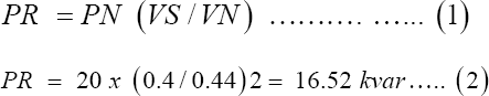
The calculation can have withheld if there is no reactive power in series with respective capacitor.
Acceptor circuit
Capacitor and cascaded reactor shows acceptor network so respective capacitor bank should remove distorted voltage and current connected with CB. Acceptor circuit basically filtrate the higher order harmonics which is the capability of that circuit termed as detuning factor which is defined by formula

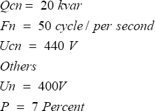
Typical range of higher order harmonics limited includes 5th and 7th harmonics. Which are usually present in the main and biggest share is involve in supplying current. The data taken for the calculation below is Capacitor
The ratio M indicates to find total capacitor with required power when reactor is cascaded in it.
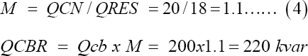
For number of capacitors the required power should be distributed. For required capacitor rating ZES SILKO Company was chosen because it is pronounced company among different supplier.
CSADG 1-0,44/20,1 capacitor
Gas filled capacitor 20Kvar: Gas filled Capacitor CSADG 1-0.44/20 from ZES Silko With N2 Dielectric used for power factor correction are used in power three phase networks 440V, 50Hz and capacity 20kvar, the figure is shown below Figure 4.

Other we use are
CSADP 3-0, 44/40, 5 capacitors
Main Circuit Diagram: For connection diagram of capacitor bank, we draw both control and main circuit diagram. The respective switchyard is connected to capacitor bank. There is three stage network incomings to supply the capacitor bank from the feeder, the incoming power is distributed through the bus bars then onward. The cross section of the bus so current can be withheld very carefully Flowing through the device. for capacitor bank, there are three insulators which gives short circuit strength of about 20-30kA.The connection L1,L2 and L3 represents the point of connection of the capacitors and respective reactors with the bus bars (Figure 5).

The three cooper bus bars L1, L2 and L3 are connected through the wires to the switch disconnectors F-F6. All switch disconnectors has the same current strength of 160A. The terminals 2,4,5 of each disconnector are connected to the three phase reactor (D1-D5). Each reactor has thermal protection (contact 11 and 14). Next, the reactors are connected in series through the contactors (K1-K5). The terminals A1 and A2 (coil of the contactor supplied by 230V AC source) trip the contacts of the contactor.
Control Circuit: Control equipment is very important for the protection needs to terminal stripe. It will cross all network to make the circuit work.
Conclusion
Power capacitors techniques are most common for reactive power compensation. Many companies provide capacitor bank components which needs to be compared [1-6]. I compared all the capacitor bank components offered by manufacturers. It was very time consuming task, since I had to pay attention to each detail regarding functions and features of power factor regulators, the parameters of power capacitors, reliability of contactors and reactors. The more complicated task is determining the rating of capacitor with detuning factor 7 percent then the main and control circuit diagram is determined.
References
- Alexandra VM (2006) Electric Power Systems: A Conceptual Introduction (Wiley Survival Guides in Engineering and Science)sl : Wiley-IEEE Press.
- Praca Z (1996) Poradnik inzyniera elektryka. Tom 2. Warszawa : Wydawnictwo Naukowo Techniczne.
- Czarnecki L (1983) Reactive power under non sinusoidal conditions: IEEE Tran. on Power Apparatus and Systems.
- Kopka J (2010) Power Factor Correction-Design of automatic capacitor bank. Wroclaw: Wroclaw University of Technology.
- EPCOS. MKV Power Electronic Capacitors.
- Walidziak, Tomasz. Kondensatory energetyczne niskich i rednich napi Olsztyn: Elma Enegria.


