Implementation of Open-Source for Outdoor Multirotors Helicopter
Sulaiman Sabikan1*, Nawawi Sophan Wahyudi2
1Faculty of Engineering Technology, Universiti Teknikal Malaysia, Malaysia
2Faculty of Electrical Engineering, Universiti Teknologi Malaysia, Malaysia
Submission: January 26, 2018; Published: February 23, 2018
*Corresponding author: Sulaiman Sabikan, Faculty of Engineering Technology, Universiti Teknikal Malaysia, Malaysia, Tel: +606-2346840; E-mail: sulaiman@utem.edu.my
How to cite this article: Sulaiman Sabikan, Nawawi Sophan Wahyudi. Implementation of Open-Source for Outdoor Multirotors Helicopter. Eng Technol Open Acc. 2018; 1(1): 555552. 10.19080/ETOAJ.2018.01.555552
Abstract
This paper presents an Open-Source Project (OSPs) platform for autonomous Unmanned Aerial Vehicle (UAV) that can be implemented in most of the outdoor applications or even in research experimental purposes. The OSP platform is one of the most popular approaches for whose demanding faster and low initial cost platform development in robotics system as well as for aerial vehicles. Besides that, the main reason is their design flexibility in both hardware and software. The explanations in the OSP platform approach and configuration for autonomous flight is presented and applied. This paper also provided several outdoor experiments results in uncontrolled environment that have been executed using our developed test bed to evaluate their performance, such as attitude and altitude stabilization, interference and vibration effect, and 3D trajectory mapping generation. In addition, we has been successfully extended this OSP development approach in preparing six and eight rotors aerial vehicle system. Finally, throughout this project, we have shown and proven that the OPSs platform for outdoor multirotor development promising a flexible solution.
Keywords: Unmanned aerial vehicle; Open-source; Multirotor; Outdoor Implementation
Abbreviations: OSPs: Open-Source Project; UAVs: Unmanned Aerial Vehicles; GCS: Ground Control Station; GIS: Geographic Information System; MSL: Mean Sea Level; GPS: Global Positioning System
Introduction
In recent years, there has been an increasing interest in the implementations of multirotors helicopter technology in the real world; for instance for real estate photography, aerial surveying, periodic forest monitoring, search/rescue missions [1] and IoT sensor networks [2]. A basic multirotors helicopters platform are consists of a flight controller, stabilization sensors [3], and propeller system powered either by fours, six or eight BLDC motors. Generally, different applications required different external sensors which should be installed on the vehicle. External sensors are used for additional tasks required for specific applications, such as global positioning, capturing images or video and obstacle detection. Periodic forest monitoring application, for example, may require onboard HD camera sensor and GPS receiver sensor. Besides the use of a variety of applications, the same multirotors platform can still be used. We called this basic platform is test bed platform, which means only consists.
The development of a multirotor test bed platform is undoubtedly important in order to validation the performance and effectiveness of control strategies in a real environment before can be extended into different application. A test bed platform must have a capability to control their takeoff and landing, flying with stability, have customization flexibility in the software and hardware, and controllable from the ground station. Therefore, there are quite many researchers around the world were successfully developed a multirotor test bed platform to assist their research work, and that platform can be extended into real beneficial applications.
There are many issues in the design and development of a multirotor test bed; such as research requirements, the scope of target applications, and overall costs. Swam multirotor research prefers to use lots of small and low cost platform [4]. Otherwise, search and rescue operation are preferred to use commercial multirotor platform [5], which has capability to provide quality sensors information, satisfactory flying duration, supported with collision free navigation and information sharing capability. Furthermore, several researchers need a test bed to be used only for specific purpose experiments in the indoor laboratory environments [6].
The development of the multirotors can be categorized into three differences approaches [7]. The first approach is by constructing their own design to suit for their dedicated purpose or as a ground test bench. The second approach is by purchasing commercial aerial vehicles as a test bed for experimental purpose or directly applied into specific real implementation. Third approaches assembly a multirotors system by using open- source project (OSPs) platform [8].
However, this paper presents on the implementation of an OSP platform for the multirotors with provide results their flying performances from the real outdoor experiments. Flexibility for customization in both hardware and software is our main reason to develop a multirotor system using open-source platform. We have been successfully developed three different multirotors with different specifications and application. In addition, this approach has low cost and save time.
The open-source project platform development refers to any designing system whose the main architectural design is based on the open resources which has been developed as a public collaboration and made freely available for use, modification or customization. It is open-ended for custom applications and increasingly easy to use even for a novice user In the case of the multirotors open-source project, its required open-source in both software and hardware. We need open-source ground control software that is compatible with variety of flight controller. At the same time, we need to consider the mature flight controller hardware design with continued firmware update support. Various open-source projects software for unmanned aerial vehicles (UAVs) are available in the markets that we can freely use [8].
The main motivation of this work is to propose another approach in preparing the multirotor platform which has full flexibility in terms of hardware and software parts. That means, our platform development approach can be extended to be implemented in any applications of the multirotor, without changing the low level controlling system, electronic hardware components or ground control station software. For example, if our target application required carrying an additional payload, the more powerful propeller system and higher battery capacity need to be considered, without changing the design architecture, flight controller or ground control station software.
This paper will start with a brief overview of the Arducopter multirotor OSPs, which includes Ground Control Station (GCS) software and the multirotor main hardware components. It will then go to the explanation on our multirotor UAV configuration, in Section 0. Section 5 presents several experiments results from flying multirotor in the outdoor environment, and in the end, we summarize our findings and experiences in this implemented project.
Open-Source Project for Multirotor UAV
Arducopter is the most advanced, full-featured, reliable autopilot open- source software and designed from the Arduino framework, for controlling multirotors system, and it can be installed on many different hardware systems (PC, Linux, and microcontrollers). This open-source also supports more unusual frame types including the single and coax-copters. The open- source code base means that it is rapidly evolving, can be audited and can be suited with many peripheral interfaces. Those are interesting parts of an open source.
Hardware for outdoor implementation
There are four mandatory hardware components to develop outdoor multirotors;
i. Flight controller is the main processing board,
ii. Propulsion system,
iii. Internal and external sensors, and
iv. Wireless communication between onboard controller and the ground station.
Flight controller: The main advantages of OSP software is run on many different flight controller boards, which is the most important board hardware for processing and operations of the UAV system. The newest flight controller features built- in vibration isolation, 3 IMU's for redundancy, and temperature control for controlling the motor, interfacing with internal or external sensors, communicate with ground control and implementing the control laws. Arducopter can run with APM, Pixhawk, PixRacer flight controller
Propulsion system: The propulsion system is composed of Brushless DC motors (BLDC), Electronic Speed Controllers (ESC), and propellers. Each component has its own performance characteristics and region of maximum efficiency The selection and combination of each component is crucial in achieving an overall propulsion system which is well suited to the application and efficient [9]. Almost all multirotors are actuated by BLDC motor. A multirotor requires sets of counter propeller pairs for balancing its aerodynamics, but the selection of the most efficient propeller requires finding out the propeller with the highest thrust to current ratio.
Internal and external sensors: Internal sensors are used for vehicle stabilization and an external sensor for vehicle positioning. IMU, magnetometers, and barometers are common sensors in the stabilization control system, while the GPS receiver is the easiest method for outdoor vehicle positioning. GPS provides a practical, easy-to-use and the most suitable sensor for outdoor vehicle positioning, such as car, rover, and aero plane. However, for accurate position estimation and mapping, researcher are turning to vision sensor systems for indoor application [10] or combined the GPS reading with IMU measurements [11].
On the other hand, lots of external sensor or devices can be integrated easily with Arducopter, such as power modules, rangefinders, optical flow sensor, cameras & gimbals, OSD for FPV, servo, relay, switch, UAVCAN ESCs, EPM gripper (EPM688), PPM encoder, received signal strength indication (RSSI), external LEDs, parachute, joystick or gamepad, buzzer, landing gear, precision landing (IR Lock), ADS-B receiver, and companion computers.
Wireless communication systems: Several options are available for multirotor wireless communication system, however, with slightly different protocol and purpose. In this project, a radio telemetry unit and RC transmitter are used to support real time digital communications between the onboard multirotor controller and the ground control station.
Ground control station (GCS) software
The Ground Control Station (GCS) is application software that runs on a ground-based computer and communicates wirelessly with the UAV. Generally, GCS is used to configure vehicle parameter, controlling, and continuously monitoring the UAV status at a real time.
Mission Planner Version 1.3.30 was selected in this project for our ground control station. It was widely used for fully- autonomous multirotors UAV system. Mission Planner is a fully featured GCS running on the Windows Operating System and several different types of commands that can be used within the missions. With appropriate telemetry hardware we can monitor, record telemetry logs which contain much more information the on-board flight controller logs, view and analyze the telemetry logs and operate your vehicle in FPV (first person view).
Multirotor Platform Configuration
To understand the basic design of multirotor, we started with quadrotor configuration system, which is consisting of four actuators. The development process of quadrotor open-source based platform can be divided into two major parts, which are hardware assembling and followed by hardware tuning using ground control software.
Hardware setup
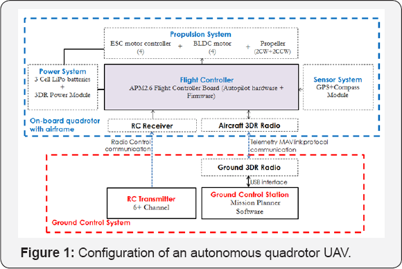
Our autonomous quadrotor UAV system configuration for this project is shown in Figure 1. That was designed for a very minimum requirement in order to implement outdoor autonomous flight mission. This configuration composed of two elements; an on-board quadrotor with airframe and a ground control system.
In the on-board quad rotor (blue box) it shows the connections of the essential electrical components (e.g. propulsion, power, sensor and communication) of a multirotor on flight controller board. A quadrotor structure airframe consists of the main centre plate (allocated for assembling the flight controller, battery, sensor and communication devices) and four arms to support the propulsion system. We used the X- configuration quad rotor frame to mount all electrical and mechanical multirotor components. We need to do carefully fitting (i.e. placed in the centre of gravity frame and in the correct direction) the flight controller board and we recommended supporting it by a bumper system. It is helpful to reduce vibration effects from the motors. The propulsion system is composed of four BLDC, four ESC, and four propellers.
We prepared two types of communication system to communicate between an on-board quadrotor and the ground control, there are a Radio Control (RC) system (i.e. include RC transmitter and RC Receiver) and Telemetry System (i.e. Ground 3DR Radio and Aircraft 3DR Radio). The RC receiver device and aircraft telemetry radio device were connected with the flight controller board, while 3DR radio device were directly connected into the USB port of the ground control station. Basically, both communications are used for initial flight configuration, realtime flight monitoring and to manually control quadrotor movement and orientation.
Software setup
Software setup of the Arducopter includes downloading and installing the Mission Planner GCS, loading the firmware into flight controller and then performing initial configuration and calibration. The most critical step is performed controller parameter setting. Mission Planner is an open source software, free to customize and available for Windows OS. The installation process is straight forward. After the Mission Planner installed onto the computer, the appropriate firmware can be downloaded to the autopilot via USB cable.
Quadrotor flight controller is required to calibrate directly using the Mission Planner software. That configuration includes airframe structured are used, the RC transmitter/ receiver setting, compass, accelerometer, and the ESCs. This is a mandatory step before the first flight and it is recommended to first starting to use quadrotor in several different flight modes before progressing to the next steps.
The next steps are performed quadrotor PID controller parameters in order to get best respond and optimal flying performances. It involved Roll, Pitch and Yaw controller tuning parameters.
Multirotors by OPS Platform
This main different among the multirotor is the number of motors. The quadrotor design methodology still can be applied in others multirotors. Arducopter is one of the full-featured open- source multicopter UAV controller and it is capable to support a wide range of multicopter aircraft (including helicopter) and with the full autonomous capability. To prove that this approach is really working, we has been successfully developed three types of autonomous flying vehicles, there are quadrotor (four- rotors), hexacopter (six-rotors) and octacopter (eight-rotors), as shown in Figure 2. Each of them has been developed for different purposes and applications. Our quadrotor are designed as a research testbed in measuring outdoor system latency by using motion analysis sensor Beside that, we have been using this quadrotor design methodology during conducting professional training course for the higher educational community.

Meanwhile, hexarotor is specially designed for Photogrammetry imaging applications by using an integration of multiple sensors (HD camera, GPS sensor). For that application, a mission flight path had been created first using the Mission Planner before it can fly autonomously. Then, the images were taken from flying hexacopter can generate map model created by the Maptitude Geographic Information System (GIS) and mapping software. The output of this project is a 3D map model of real-world object or land mass. This aerial mapping technology has been implemented on forestry management and planning by our research team. In addition, we also have an octarotor developed from this OSP platform. It is the most advanced aerial vehicle with more payload capacity and flying time. The purpose of that octacopter development is for aerial surveillance application within the more challenging environment, such as in along coastal areas. Currently we are working on designing and developing coastal control surveillance for monitoring immigrant activities, marine oil spill or marine pollution.
Outdoor Flight Experiments Results
In this section, two outdoor flight experiment results done by our quadrotor vehicle as shown in Figure 2a are presented.
i. Quadrotor flight performances and
ii. Multi-way point flight 3D trajectory
These experiments were conducted in sequence and all analysis with excerpts from the quadrotor MAV link telemetry raw data.
In the first experiment, some basic that related to quadrotor performance will be examined; such as attitude and altitude stability, compass sensor magnetic interference effect, and vibration effect. After we had satisfied with first experimental results, next experiment will be conducted that aims to examine the flight route accuracy and generate a 3D trajectory mapping. To perform this second experiment, we have utilized the Mission Planner features of the ground control software. Automated mission planning with five way points are selected randomly before launching the flight mission for several times. All waypoint locations were designated from the GPS coordinate system.
Arducopter platform has offered two ways to collect flight data from multirotor. These two methods are able to record very similar data, but in different ways. Firstly, it is recorded by on-board data flash memory on the flight controller, which is preferred as "data flash logs" On a multirotor, data flash logs are created soon after their first arm. These data flash logs can be extracted from an autopilot via USB connection after a flight. For instance, APM2.6 autopilot has only 2MByete on-board data flash memory size. However, with that size of amount of memory, it is very limited and not sufficient to record long running flight data, especially for continuous or repeated missions. Despite that, it is generally recommended method for mechanical failure diagnosis because of the higher data stream rate. Secondly, the platform is recorded directly to the ground control station computer, which is preferred as "telemetry logs” or in short form as known as "tlogs”. Telemetry logs can collect similar information as well as data flash logs. The MAV link wireless telemetry communication protocol is used to transfer flight data between the on-board flight controller and the ground station computer. Without telemetry devices, we cannot communicate in real-time with our flying multirotor as well as transferring flight data. The "tlogs” file is automatically created and stored in the Mission Planner's logs folder. Flight recording will start from connecting flight controller until disconnected from the ground control software. Besides that, this second method has the ability to record all flight data throughout the mission with desired stream rates without limited memory, as long as our computer has a memory space allocation. Furthermore, several others advantages of using telemetry method are; recorded data that can be easily played back flight missions, able to convert the "tlogs” file to the KMZ file format and also directly generate graphs of any flight parameters. All of these can be done from the ground control software. Therefore, we have used the second methods to collect fight data throughout these experiments for analysis purpose. Moreover, all experiments were conducted without adding any payload and did not take into account of the current environmental situation, such as wind gust conditions.
Quadrotor flight performance
The other features of Mission Planner software are their capabilities to generate an automated report in the form of visual graph from both recorded data logs (data flash and telemetry), in order to diagnose any problems or to evaluate multirotor performances. From this multirotor experiment, we present the three commonly flight data analyses that have been used to evaluate their performance, which are; quadrotor attitudes and altitude stability, magnetometer interference effect and quadrotor vibrations.
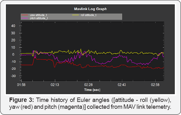
Quadrotor attitudes and altitude stability: An emphasis of aerial vehicle performance analysis, especially in attitude and altitude stabilization is very important to ensure flying stability in an uncertain outdoor environment. Attitude controller quadrotor comprise of stabilization of three Euler angles (roll, pitch and yaw). Figure 3 shows the result of attitude stability of our quadrotor autonomous flight within three straight waypoints and quadrotor will stop for 3 seconds on each way points. The Figure 3 presents time history of three angles and has represented in different colors. The roll and yaw angles are more stable along the flight, but for pitch angle, it looks gradually increases while leaving from each waypoint. However, from our experiments, this result is one of the best after various changing in PID control parameter.
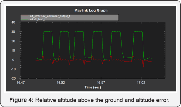
Altitude is measured using either mean sea level (MSL) or local ground level (AGL) as the reference datum. From our experience, the relative altitude above ground is given a more stable reading compared with altitude above sea level from GPS raw data. It is because of the relative altitude above the ground is the filtered global position (e.g. fused from GPS and accelerometers). In our conducted experimental place, altitude from the sea is about 20 meters and our flight mission is set for 30 meters from the ground level. Figure 4 provides the experimental data on the relative altitude above the ground and altitude error output from navigation controller. It is given the fluctuated ranges below than 0.65 meters after passing the takeoff position. While on the takeoff and land mode, it has given error around 3.5 meters. That means, our flight altitude control still can be acceptable for unpredicted wind gust magnitude in an outdoor environment.
Magnetometer interference effect: Magnetometer or compass sensor is quite sensitive with magnetic field interference. Compass interference could be comes from the power distribution board, motors, battery, ESC and other electrical devices near with sensor. It will cause interference on a compass, then giving inaccurate reading. Because of that, we decided early in this project to not use the embedded IMU internal compass and prefer to utilize an external compass.
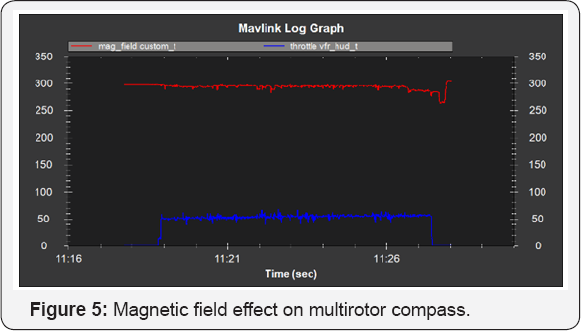
Figure 5 shows the graph of magnetic field (red) and percentage of throttle (blue).The magnetic interference value starts to fluctuate when the throttle is raised. An acceptable amount of magnetic interference should be less than 30% of normal value. In the place of our conducted experiment, the normal magnetic interference reading is 297 milligauss. The results of this experiment show that the magnetic field only fluctuated between 10% and 20% and this result is acceptable.
Quadrotor vibration: High vibrations on the flight controller caused our quadrotor accelerometer based altitude and horizontal position estimates to drift far off from expectation. Thus, it will create problems with altitude hold or loiter Vibrations are best viewed by graphing the data flash's IMU message's AccX, AccY and AccZ values because data flash logs provide higher recording rate up to 50Hz. However, telemetry tlog's RAW_IMU xacc, yacc and zacc can also be used to examine the vibration. The acceptable range for xacc and yacc is -300 ~ +300, and for zacc is -500 ~ -1500.
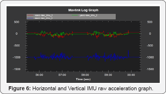
In this project, Figure 6 shows the graph of raw IMU data [i.e. horizontal; xacc (red) and yacc (green), vertical; zacc (blue)] obtained from the MAV link telemetry logs during AUTO mode flight. From the graph we can see that both horizontal and vertical vibrations are within the acceptable range as mentioned above. Interestingly, the vibration ranges still in acceptable range in all our conducted experiments. These findings suggest that by mounting the flight controller on the top of the Anti-vibration Plate on the multirotor frame will reduce vibrations in IMU sensors. But, balancing propellers and motors are also very important to get better results.
Multi waypoints autonomous flight mission
We have performed several autonomous flight missions with different flight routes, simple to complex routes. Quadrotor flight routes need to create beforehand by using the mission planner software and no ground pilot's interactions during the flight mission. In this paper, we present a simple straight waypoints and different point for home and landing. Five way points were selected randomly in straight alignment with additional 3 second delay that was added inWP2 to WP6. The flight altitude is set at 20m height throughout the missions. The waypoint navigation speed setting are; linear speed is 700cm/s, radius speed 200cm/s, speed up rate is 250cm/s, speed down rate is 150cm/s and loiter speed is 1000cm/s. We run this flight mission for four times.
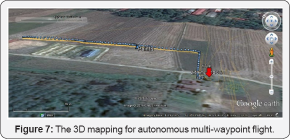
The aim of this experiment is to demonstrate 3D mapping flight trajectory generation from telemetry logs. After complete four flying missions, telemetry logs file can be converted directly into the KMZ file format. A *.kmz and *.kml file will be created alongside the original. tlog and this can be opened in Google Earth (or any Earth Viewer 3D) to interactively view the 3D flight path, as shown in Figure 7. In that figure, we present one route instead of four flight route missions conducted in this experiment.
Conclusion
In this paper, we have present on general view on the implementation of the OSPs multirotor platform to develop a multirotor research test bed and should be easily extended to use in almost any outdoor application, especially for where autonomous flight mission is required. An example of quadrotor test bed configuration, in terms of hardware and software, which have the capability to perform in autonomous flight mission are also presented. Then, several experiments were conducted in the outdoor real environment in order to investigate their elemental features of flight performances, such as attitude and altitude stabilization, compass interference, vehicle vibration, and multiwaypoint autonomous flight trajectory, also presented here. In addition, we have been successfully developed a fully functional six-rotor and eight-rotor copter using the OSP platform.
Several advantages of the OPS multirotor platform are offered flexibility in the design solution, which is flexible in design of software and hardware, and relatively low initial cost. Instead of Arducopter OSPs platform, a lot of OPS platform offers a solution in developing a multirotor. Basically, we preferred OPS which have hardware support, continuous firmware updating and that have attracted community from all over the world.
As a conclusion, from our experiences and findings in this project, the OPSs multirotor platform offers complete frameworks in both hardware and software aspects and they convey in designing flexibility to suit our research purpose or any project implementations. In a near future, we will focus on the multirotor system latency modelling, obstacle detection and collision avoidance algorithm by using the same platform.
Acknowledgement
This work was performed under financial support from the Universiti Teknologi Malaysia, Ministry of Higher Education Malaysia and Universiti Teknikal Malaysia Melaka.
References
- Dong W, Gu GY, Zhu X, Ding H (2015) Development of a quadrotor test bed - Modeling, parameter identification, controller design and trajectory generation. International Journal of Advance Robotic Systems 12(2).
- Yoo S, Park J, Kim K, Shrestha A (2016) Flying path optimization in UAV- assisted IoT sensor networks. ICT Express 2(3): 0-4.
- Liu C, Prior SD (2015) Design and implementation of a mini quadrotor control system in GPS denied environments. International Conference on Unmanned Aircraft Systems ICUAS, USA, pp. 462-469.
- Davis E, Nizette BE, Yu C (2013) Development of a Low Cost Quadrotor Platform for Swarm Experiments. In Proceedings of the 32nd Chinese Control Conference, China, pp. 7072-7077.?
- Waharte S, Trigoni N (2010) Supporting Search and Rescue Operations with UAVs. Emerging Security Technologies (EST), UK.
- Abdolhosseini M, Zhang YM, Rabbath CA (2013) An efficient model predictive control scheme for an unmanned quadrotor helicopter. Journal of Intelligent & Robotic Systems 70(1-4): 27-38.
- Sabikan S, Nawawi SW (2016) Open-Source Project (OSPs) Platform for Outdoor Quadcopter Journal of Advance Research, 24: 13-27.
- Lim H, Park J, Lee D, Kim HJ (2012) Build your own quadrotor: Open- source projects on unmanned aerial vehicles. IEEE Robotics and Automation Magazine, 19(3): 33-45.
- Gabriel DL, Meyer J, Du Plessis F (2011) Brushless DC motor characterization and selection for a fixed wing UAV. IEEE AFRICON Conference, Zambia, p.13-15.
- Gupte S, Mohandas PIT, Conrad JM (2012) A survey of quadrotor unmanned aerial vehicles. In Conference Proceedings - IEEE SOUTHEASTCON, USA, p. 1-6.
- Singh S (2004) Application of robust, high-accuracy positioning for autonomous ground vehicles. AUVSI Unmanned Systems, North America.


