




 CERJ Home



Abstract
The Uma Oya Multipurpose Development Project (UOMDP) in Sri Lanka, consists of two major dams with an inter connecting 3.7km link tunnel constructed by conventional drill and blast method, a 15 km headrace tunnel transferring the water to a 840 m deep raise bore shaft leading to an underground power station, and a tail race tunnel. The 15 km headrace tunnel for the Uma Oya project in Sri Lanka was excavated by double shield TBM and caused ingression of large quantities of water which impacted the local environment and the local communities. Research carried out during this project provided a better understanding of the effects of the tunnel on the hydrogeology of the area, and determined the most appropriate techniques for addressing these impacts. These observations are presented in this paper.
Keywords:Ground Water; Aquifer; Wells; Ingress; Khondalite
Introduction
This research is a case study of the construction of the headrace tunnel for the Uma Oya Project in the Uva Province, Sri Lanka and was carried out between August 2015 and September 2018. The 15.2 km Headrace Tunnel (HRT) of the Uma Oya Project was excavated by a fully mechanised double-shielded tunnel boring machine (TBM). This is the first time a TBM has been used for tunnel construction in Sri Lanka. The excavation was completed in October 2019. During the excavation, there were a number of water ingress incidents that caused drying of surface wells up to 3 km distance away from the tunnel alignment within a few days of such ingresses, widespread damage to buildings due to settlement and loss of agricultural crops due to drying out of the surface soils. This paper outlines the steps taken to better understand the geology and hydrogeology of the area and identify the most appropriate methods of tunnel construction to overcome such problems.
Previous Work
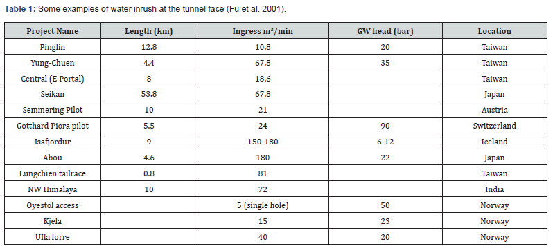
The aquifers of the Central Highland area of Sri Lanka are somewhat unique, consisting of a shallow regolith aquifer, and a deep fracture zone aquifer [1]. Typically, the uppermost section of the basement rocks is altered by the tropical weathering process to form a distinct horizon of varying depth termed the regolith (Herbert et al., 1988). Most dug wells penetrate only to the top of the underlying “sap rock” horizon whilst tube wells are bored into the deeper fractured rock aquifer. As presented by Panabokke et al. [1], whilst the two aquifers are typically considered separate, the seasonal water level fluctuation also seems to show that there exists an interconnection between the two aquifers through a network of fractures in the basement rock (Hata 2003). According to Withanage (1988), similar situations have been identified before, where previous tunnel projects in Sri Lanka have caused a reduction of the near-surface aquifers due to uncontrolled water ingress into the tunnel excavations. In fact, he reports that the drying up of all wells along the 8 km long unlined Polgolla tunnel constructed between 1964 to 1968 determined the need to line all tunnels after this date. Atukorala (1992) further reports that during the construction of diversion tunnels for the Samanalawewa Hydroelectric Power Project, lowering of groundwater levels occurred in the areas situated on the tunnel routes, resulting in drying up of wells and of the cultivation lands. It is important to note that all these tunnels were constructed by drill and blast method with cast in-situ concrete linings capable of withstanding the full hydrostatic load which could be grouted to seal off all water ingress. Whilst other international projects have been successfully completed with similar challenging conditions, some other projects have also been problematic with large ingresses of water as reported by Fu et al. (2001) as presented in Table 1.
Uma Oya Project
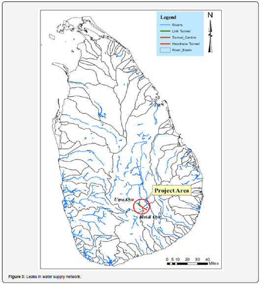
The Uma Oya Multipurpose Development Project (UOMDP) is located in the Uva Province of the south-eastern part of the central highland region of Sri Lanka (Figure 1). The UOMDP consists of three tunnels (link tunnel, headrace tunnel and tailrace tunnel) and two dams located across Uma Oya at Puhulpola and across Mahatotilla Oya at Dyraaba (Figure 2). Diverted water from Puhulpola dam will be conveyed approximately 3.7 km through the Link Tunnel (LT) into the reservoir at Dyraaba. From Dyraaba the water will travel approximately 15.3 km through the Headrace Tunnel (HRT) to the 628 m deep pressure shaft and down to the turbines in the underground powerhouse. The discharge from the powerhouse will travel via the 3.6 km long Tailrace Tunnel (TRT) into the Alikota Ara which is a tributary of Kirindi Oya (Figure 2).
The excavation of the 4.3 m diameter headrace tunnel was completed using two double shield tunnel boring machines (TBM) one from each end - with about 4 km of tunnel excavated down grade from Dyraaba at the intake and more than 10 km upgrade from the outlet. In good rock conditions with no water ingress, the HRT was excavated with no rock support and only the installation of the invert segment which was necessary to allow the rail tracks to be installed for mucking, material and transport of working personnel. In weaker ground, a full fourpiece hexagonal segmental lining consisting of pre-cast reinforced concrete segments 250 mm thick was installed. The segmental lining was supported by pea-gravel injected behind the sides of the lining to fill the annulus to the excavated rock. The invert and crown voids were filled with thick grout. The pea-gravel was then injected with a more fluid cement grout which permeates through the gravel to produce a barrier against water ingress. In areas where water ingress was excessive, grouting of the rock mass was carried out by drilling holes through the recesses in the segmental lining into the surrounding rock and injecting cement or chemical grouts. Pre-excavation grouting was carried out ahead of the face by probe drilling. The probe drill is positioned about 8 m behind the cutter head. Initially, initially drilling could only be carried out through ports in the shield between 9 o’clock and 3 o’clock positions but this was subsequently upgraded to permit grouting around the full perimeter of the excavation. In areas where water ingress was not sealed by pre-excavation grouting, this was sealed by post grouting.
Geology
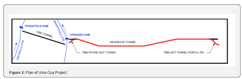
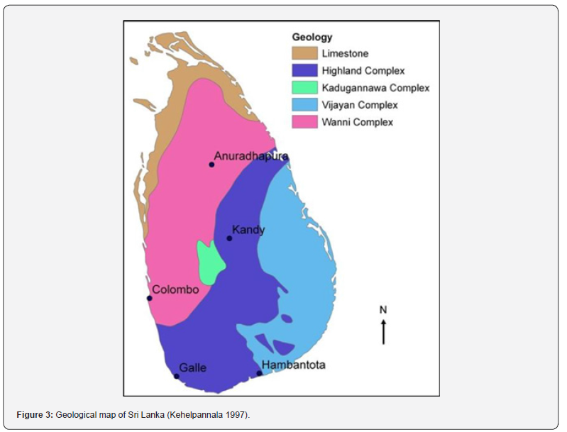
The project area is located in the Highland Complex (HC) area, as shown in Figure 3. The rocks of the HC are Precambrian rocks formed under high grade metamorphic conditions and are composed of two main types of rocks, namely metasediments and charnockitic-gneisses. The metasedimentary rocks are metamorphosed sedimentary rocks consisting of garnet sillimanite gneisses or khondalites, quartzite’s, quartz feldspar granulites, garnet gneisses, marble and impure crystalline limestone. However, charnockitic gneisses are the most common rock types of the Highland Complex.
Deep weathering of the garnetiferrous granulitic gneiss rock produces deep rich soils and often a deeply weathered rock mass to over 200 m. The majority of the HRT trace passes through charnockitic gneiss that is often interbanded with leucocratic quartz feldspar gneiss abundant with pink garnet, and is characterised by large scale folding and thrusting. Rock bands of the area display their main foliation which can be related to the main deformation phase. These bands are refolded to open synforms and tight antiforms. Lineaments are clearly marked by elongated valleys.
Initial concern for the project was the presence of calc-silicate/ marble and quartzite (Dietler 2011). However, the calc-silicate was found to be largely homogeneous and dry at the depths being excavated, with the exception of some unique hydrothermal cavities, and excavated sections of quartzite in the tunnel caused only minor water ingress.
The problematic rocks in this tunnel were khondalite (garnet sillimanite graphite gneiss) and charnockite. Due to intense weathering the khondalite created large storage areas for underground water and direct connectivity between the lower and upper aquifer. Due to its brittle nature, open fracturing in the charnockite created by fold structures (particularly antiforms) extended through the rock mass creating connections to the overlying aquifers.
This research showed that there is a hydraulic continuity of the deeply weathered khondalite over large areas. Where there is deep weathering of the khondalite, the upper and lower aquifers in the area are co-joined, and lineaments and shear zones along river valleys in the area influenced the flow of groundwater over large areas (Lees and Gunatilake, 2017). However, this research has concluded that there is not a strong connection between the surface wells and the deep aquifer in areas of charnockite.
Hydrogeology
Understanding the hydrogeology for the Uma Oya project started late. Surface monitoring commenced in July 2015 to monitor “All buildings, domestic wells, deep wells, surface reservoirs and streams within a corridor of 600 m width at ground level along the tunnel alignment”. Ground water monitoring of the deep boreholes began immediately after completion of the site investigation, but although these deep boreholes along the HRT and Link Tunnel were typically down to the tunnel elevation, they had been cased for their full length which meant that the measurement of the groundwater was taken across the upper and lower aquifer.
During tunnel construction, Water level of all the deep boreholes were monitored monthly over the entire length of the tunnel, and weekly in a zone for a distance 500 m behind the face and 500 m in front of the face of the excavation. Additional daily monitoring was carried out in areas where high water ingress was intercepted.
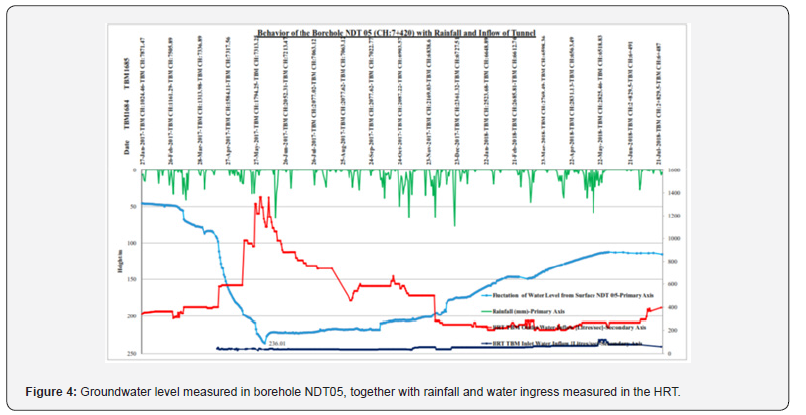
The results, coupled with rainfall and water ingress measurements in the tunnel were able to depict how the tunnel excavation effected the ground water levels as can be seen below for borehole NDT05 which was located very close to the major ingress occurred in April 2017.
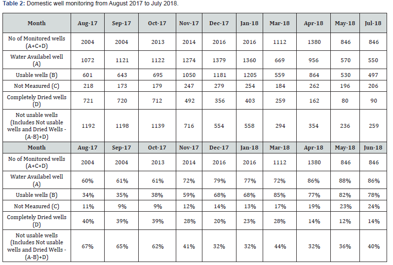
There are over 800 domestic wells along the HRT which have all been monitored since July 2015. Whilst this has not been able to determine the depths of water in these wells before the major water ingress event in December 2014, it has enabled monitoring of later events and monitoring the changes due to the seasonal rainfall, and in areas where increased ingress has been intercepted in the tunnel excavation as shown in Figure 4. Typically, little change has occurred. However, drying out, probably due to seasonal changes, has also been recorded as presented in Table 2.
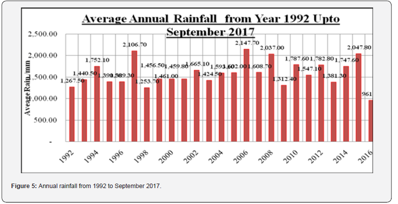
Plotting the location of these wells with respect to surface geology provided the correclation between geology and hydrogeology especially for the upper aquifer. As identified by Panabokke et al. [1] the results show that some of the wells which are further up the valley sides will be the first to dry in the drier months as water percolation through the soils is reduced as the rainfall also decreases. However, there was a drought in the area in 2016 with the only 961 mm of rainfall recorded at Bandarawella compared to an average of 1592 mm as shown in Figure 5.
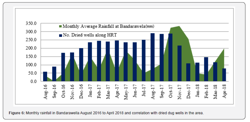
At the end of 2017 the drought was broken by the North-East monsoon in October to December and when the wells were remonitored a vast improvement in the water levels was observed as shown in Figure 6. As shown in Figure 6 the results show that the water in the domestic wells is in general a product of the rainfall, with the number of dried wells dramatically decreasing in general after the start of the rainy seasons.
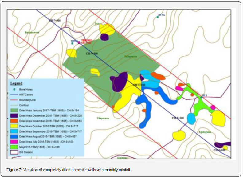
However, in the wide agricultural valley between Chainage 8+800 to 8+100, in an area of deeply weathered khondalite, the domestic wells dried as the level of the ground water in the deep aquifer dropped as recorded in the borehole DT06. Further, monitoring of the drying of the wells associated with water ingress in different sections of the tunnel presented in Figure 7 shows interesting patterns following strong lineaments and isolated spots on khondalite. Where surface streams were seen to cross the tunnel alignment, where appropriate locations were selected downstream and Parshall flumes installed to monitor the flow or, flow was measured by filling of measuring buckets.
The surface water reservoirs Panangala and Elamal Landa were also measured by establishing benchmarks on the spill way and measuring the water level depth below this benchmark. Ground water was also monitored underground by manometers on standpipes installed in boreholes in the sides of the tunnel.
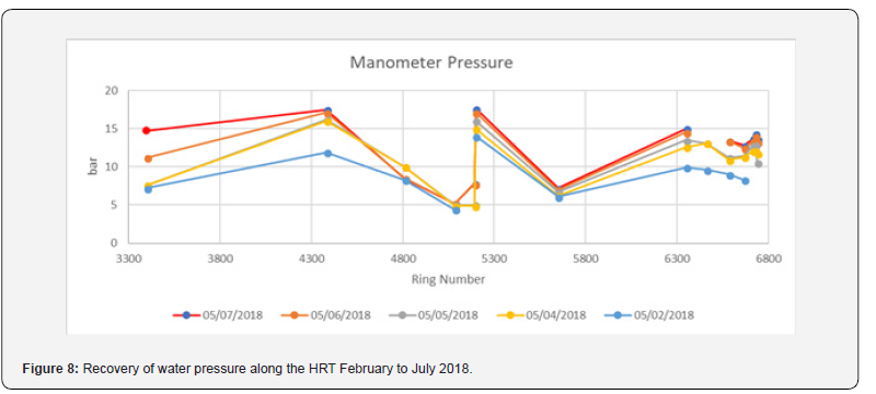
Following successful grouting some recovery was observed in water pressure along the tunnel particularly in sections where the tunnel was excavated in charnockite, but in sections of deeply weathered knhondalite such as in the Palleperuwa valley between ring No. 4800 and ring No. 5800 as shown in Figure 8 the recovery was much slower.
An interesting investigation into the ground water surrounding the excavated tunnel was carried out between Chainage 11+150 and 10+700, where three manometers were installed into the rock mass. One manometer was installed at a depth of 7 m into the rock mass (outside the grouted zone), one manometer was installed in a grouted pipe at a depth of 1.5 m (in the 4 m deep grouted zone), and the other manometer w in the segment to record the build-up of water pressure directly behind the lining.
The pressure reading of these manometers in December 2015 (after the first major water ingress and post grouting was completed) initially showed about 15 bar but decreased during the dry season to 11 bar in September 2016, indicating recovery of the water table in the lower aquifer between 110 and 150 m above the tunnel.
Previous work by Grov [2] and Schliess [3] indicated that “the impervious zone created by grouting around the tunnel ensures that the full hydrostatic pressure is removed from the tunnel periphery to outside of the pre-grouted zone and that the water pressure is gradually reduced through the grouted zone and the water pressure acting on the tunnel contour and the tunnel lining can be close to nil”.
It can only be assumed that in an unlined tunnel water ingress into the tunnel provides a reduction in water pressure as the ground water approaches the excavation. However, the manometers in the HRT were installed behind an impervious lining and there is no reduction of water pressure towards the excavation. This is why the tunnel lining for Uma Oya had to be drained, as at the depths this tunnel was constructed a fully watertight lining could not be provided. Grouting the rock mass around the excavation enabled a reduction in permeability of the rock mass and hence a reduced flow of ground water ingress into the tunnel within acceptable limits.
Dewatering of the soft soils above the tunnel and the shallow foundations on which most of the structures are founded created significant problems for the project. A building condition survey was carried out in the area of the reported cracks in July 2015 and then later this survey was extended to cover the entire length of the HRT and Link Tunnel. As such, some of the buildings surveyed were only surveyed after the event of December 2014, but ahead of the tunnel face a pre-condition survey of all the buildings within 300 m either side of the tunnel trace was established as the excavation progressed.
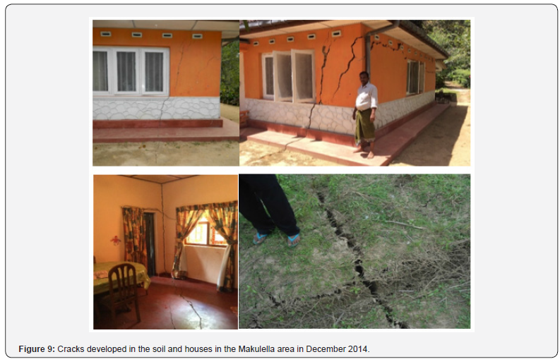
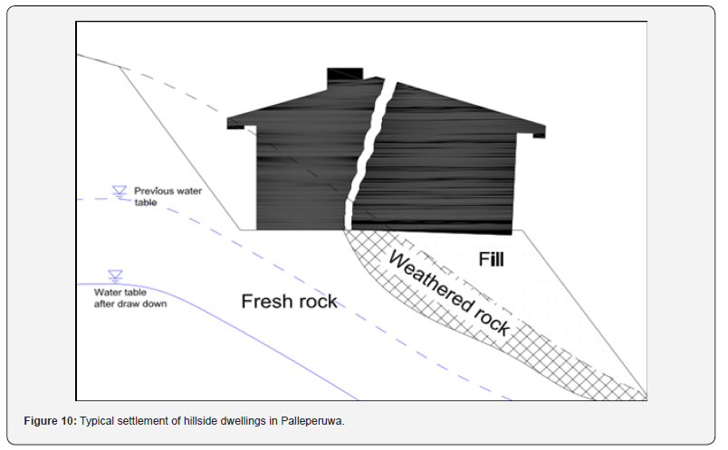
Building damage was also reported in July 2016 in the Palleperuwa area and later in October 2016 in Udaperuwa. The houses in Palleperuwa and Udaperuwa are typically constructed in cuttings into the hillside where the back of the building is founded on weathered rock and the front of the building on soft soil or fill material as shown in Figure 9. It is considered that with the drop in the water levels, the phreatic table has also dropped causing differential settlement between the front and back of the building. This distortion of the building then causes the building to crack perpendicular to the hillside as shown in Figure 10.
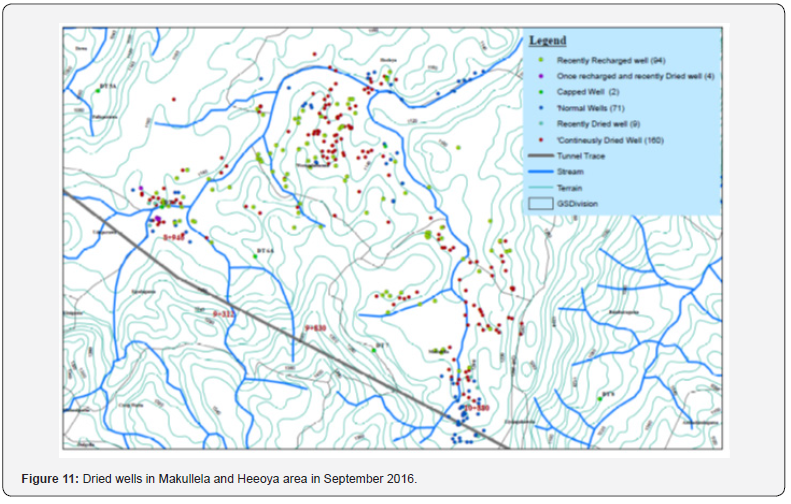
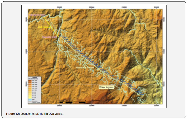
During the drought there were many calls that wells and buildings outside the expected area of influence of the tunnel were being affected. The challenge for the project was to determine which of these were due to drought and the others affected by the tunnel construction. Two particular areas are worth discussing namely Makullela and the Mathetilla Oya valley.
Wells in the Makulella area dried up to 3km from the tunnel trace within a few days of the water ingress in December 2015. These wells essentially follow the alignment of lineaments that intersect the tunnel and join otherwise isoltaed areas of khondalite. After the grouting was completed to seal the tunnel there was also evidence that these wells started to recover. This shows that lineaments may cause the groundwater to be lowered over quite large distances away from the underground excavation. The Mathetilla valley follows a strong lineament running parallel with the tunnel trace.
However, although it was suggested that the major lineaments that are crossing the HRT and connecting to this valley could be the reason this valley had dried, it is considered that the drying of the wells in this area followed the normal seasonal changes, as evidenced by the fact that most of these wells recovered after the heavy rains of the North-East monsoon in late 2017.
Hydrogeological Model
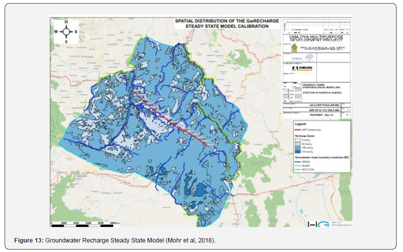
A hydrogeological model was devloped for the HRT which determined the ground water recharge for the area. One model for assessment of ground water recharge (GWR) is to look at the base flow of the rivers in the pre-project situation and assuming all GWR is ending up in the rivers [4]. The groundwater recharge is considered to be relatively low in the area of the HRT and is expected to be less than 25 % of the runoff indicating mean annual run off yielding in a groundwater recharge is about 160 mm per year or approximately 5 l/s.km2 [5].
The other method used to calculate GWR is with a soil water model taking into account rain and other weather (sun and wind, for evapotranspiration), land use (for transpiration and runoff), slope (for runoff) (Larkin and Sharp) [6] - this method gave a result of 4.4 l/s.km2 [5] which equates to 140 mm per year. Thus, taking an average of 150 mm per year over the catchment area, the run off can be calculated as 605 mm per year.
As presented by Grepstad [7] the catchment area above the tunnel is fairly simple but there was more uncertainty in determining the area of influence as a deep tunnel can also affect areas outside the catchment area. The catchment area could be defined as the contours within which the tunnel is located, but we have seen from the events in December 2014 that the effect of the drawdown occurred beyond the immediate valley, Therefore, the area of influence is defined as the no-flow boundary between major rivers giving an area of 625 km2.
Based on the limitation presented by Grov [2] that a residual
flow of more than 5 to 15 % of the mean annual flow from the
catchment areas would not be acceptable, and Kveldsvik et al. [8],
that an inflow with less than 10 % of the runoff yields has either
no, or small consequences, an inflow in the range of 10 to 20 % of
the runoff yields medium consequences, and an inflow of more
than 20 % of the runoff yields large consequences the following
can be presented:
• Less than 60 l/min/100 m of HRT (less than 150 l/s in
total) - Insignificant or no consequences
• More than 120 l/min/100 m of HRT (more than 300 l/s
in total) - Significant consequences
• It is important to note that the impact of the drought in
2016 where the rainfall was almost half the norm, then only an
ingress of less than 60 l/s would have “nominal consequences”.
The impact of more than 250 l/s on-going between 2015 and
2018 should be considered would give “large consequences”.
• This value of 60 l/min/100 m is twice that presented by
Grov [2] of 30 l/min/100 m of tunnel, Holmoy and Nilsen (2014)
of 20 l/min/100 m, or the strict limits used in Scandanavia as
presented by the Norwegian Tunnelling Society [9] of:
a. Norway 2 - 4 l/min per 100 m tunnel
b. Sweden 2 - 5 l/min per 100 m tunnel
c. Finland < 2 l/min per 100 m tunne
The conclusion of the research was that a value of 20 l/ min/100 m equating to 300 l/s for the entire HRT, is appropriate to limit the effect of ground water lowering and is also considered to be practically achievable [10].
Conclusion
The study undertaken during the construction of the Uma Oya HRT has developed a better understanding of the effect of the geology and hydrogeology on tunnel construction in the high grade metamorphic terrain of Sri Lanka. Deeply weathered khondalites create large underground ground water storage. There is a direct hydraulic connection between the upper and lower aquifer. In areas of intense folding, open joints in the charnockite directly feed ground water from the overlying aquifer into the tunnel excavation. Monitoring of wells, boreholes, streams and surface water storages needs to be done carefully and correlated with surface geological mapping to determine the effect of tunnelling and groundwater ingress into the tunnel excavation on the surrounding environment. This monitoring needs to be established well in advance of tunnel construction so that baseline seasonal changes may be detected. Determining the acceptable ingress value into the tunnel is essential and this can be achieved by calculating the ground water recharge for any given project area and accordingly limiting the residual ingress as a safe percentage of this ground water recharge.
Acknowledgment
Dr J Jagath, Professor H.A. Dharmagunawardhane, Dr John Sharp
References
- Panabokke CR, Ariyaratne BR, Senevratne A, Wijekoon D, Molle F (2007) Characterization and Monitoring of the Regolith Aquifer within Four selected Cascades (sub-watersheds) of the Malala Oya Basin. International Water Management Institute - Working Paper No 122.
- Grov E (2001) Introduction to water control in Norwegian tunnelling. Water Control. Norwegian Tunnelling, Publication No 12, Norwegian Tunnelling Society, Chapter 1, pp. 7-11.
- Schleiss AJ (1987) Design criteria for pervious and unlined pressure tunnels. Underground Hydropower Plants, Oslo.
- Schwarze R, Grûnewald U, Becker A, Frôhlich W (1989) Computer-aided analyses of flow recession and coupled basin water balance investigations. Friends in Hydrology (Proc. Bolkesjo Symp., April 1989), 75-81. IAHS Publ. no. 187.
- Mohr M, Möbus C, Wenner D (2018) Documentation of the Hydrogeological Model (HGM) and the calibration of the Noumerical Water Flow Model - Phase 2-1 (Steady State Ground Water Flow Model). Headrace Tunnel for the Uma Oya Multipurpose Development Project, Amberg Engineering.
- Larkin RG, Sharp JM (1992) On the relationship between river-basin geomorphology, aquifer hydraulics, and ground-water flow direction in alluvial aquifers. Geological Society of America Bulletin 104: 1608-1620.
- Grepstad GK (2001) The water balance - definition and monitoring. Publication No. 12, Norwegian Tunnelling Society, pp. 21-26.
- Kveldsvik V, Holm T, Erikstad L, Enander L (2001) Planning of a 25 km long water supply tunnel in an environmentally sensitive area. Publication No. 12, Norwegian Tunnelling Society, pp. 65-74.
- Norwegian Tunnelling Society (2011) Rock Mass Grouting. Publication No. 20. Norwegian Tunnelling Society, Oslo.
- Holmøy KH, Nilsen B (2014) Significance of geological parameters for predicting water inflow in hard rock tunnels. Rock Mechanics and Rock Engineering 47(3).