Flow Rate of the Radial Injection of Cement Mix in a Rock Fracture
Mohamed El Tani*
Rockgro Consulting, Beirut, Lebanon
Submission: April 25, 2018; Published: May 25, 2018
*Corresponding Author:Mohamed El Tani, Rockgro Consulting, Po-Box 11-9054, Beirut, Lebanon, Tel: +961 70 649191; Email: info@rockgro.com
How to cite this article: El Tani M. Flow Rate of the Radial Injection of Cement Mix in a Rock Fracture. Civil Eng Res J. 2018; 5(2): 555657. DOI: 10.19080/CERJ.2018.05.555657
Abstract
A parametric relation to the radial injection of cement mix in a rock fracture is sought in the framework of the first order expansion of the lubrication model. The first order expansion challenges the zero order expansion leading to a solution that satisfies the mass and momentum equations and energy balance in its integral form. A closed form relation for the flow rate is deduced from the analytic solution. The flow rate relation has a useful application. It transforms the spread objective during grouting into a flow rate objective.
Keywords: Grouting; Stop criterion; Viscoplastic; Closed form
Introduction
The sealing of crystalline bedrocks is generally achieved filling the fractures with cement mix. A borehole is drilled to the fracture. A segment of the borehole containing the fractures is isolated with packers. It is filled with cement mix that enters the fractures when the pressure in the borehole exceeds the in-situ water pressure. This is the injection process that is idealized as a pressure driven flow of a viscoplastic material between rigid parallel discs [1-3]. Two main quantities are continuously registered during grouting: the volumetric flow rate of the mix and the injection pressure which is the excess pressure in the borehole to in-situ pressure. These two quantities are used to monitor the grouting process to attain the grouting objective [4].
The analytic solution of the 1D injection of a viscoplastic material between parallel plates is probably as old as is the formulation of Bingham [5] on the behavior of a viscoplastic material. It can be found in a monograph by Prager [6] with its corresponding volumetric flow rate at a constant injection pressure. The volumetric flow rate was extended by Dai & Bird [7] to the radial injection between parallel discs using analogies. Since the radial flow rate was not obtained solving the governing equations its validity may be questioned. Further investigations have shown that it is not wrong [8] and can be deduced from the zero order solution of the radial injection of a viscoplastic material in the frame of the lubrication model. The governing equations of the radial injection are nonlinear and cannot be solved analytically without making the assumption that the mix thickness is small in comparison to the dimension of the injected fracture. This assumption is the basic hypothesis of the lubrication models. The analytic solution that is obtained in the frame of the zero order expansion does not satisfy the momentum equation [9]. This inconsistency is resolved in this note considering the first-order expansion and normal stresses. The lubrication frame leads to a simplified set of governing equations [10]. The solution to these equations may be obtained numerically or analytically in a weak form. It is the latter form that will be sought and obtained requiring that the solution satisfies the energy balance in its integral form. This implies the consideration of gross quantities since in its integral form the energy balance indicates that the power expended by the injection mechanism is equal to the total rate of dissipated energy by viscoplastic effects.
The definition of a viscoplastic material is presented in Sec 2. This section contains also the definition of the pseudo-core and the local dissipated energy. The basic quantities that are used in the injection of a rock fracture are presented in Sec 3. This latter contains also the main findings obtained in this note concerning the volumetric flow rate and the closure relation. Their usefulness in deciding on where and when, to stop the injection is also discussed. Sec 4 is technical and contains the mathematical proof that leads to the main mentioned findings; the governing equations, boundary conditions, gross energy balance, and naturally the analytic solution that consists in the pressure, velocity, stress fields and some related gross quantities are listed there.
Bingham material
In a shear experiment a Bingham material remains rigid when the shear stress does not exceed a threshold value called the yield stress. When the shear stress exceeds the yield stress it behaves like a Newtonian fluid. Modeling an incompressible viscoplastic material as a Bingham material has often led to inconsistencies predicting a solid behavior when actually the material is yielding [11]. Wilson [12] proved that the inconsistency is due to a flaw deriving from Bingham’s relation that neglects normal stresses. This finding favored a 3D generalization of Bingham’s material by Hohenemser & Prager [13] based on the invariants of the stress and shear rate tensors. HP relation is

where c , η , τ and γ are the yield stress, dynamic viscosity and deviatoric stress and strain-rate tensors. II τ and II γ are the second invariants of the deviatoric stress and strain rate tensors. A viscoplastic material according to HP remains rigid whenever the second invariant of the stress tensor does not exceed the yield stress. From the above relations it is deduced that

The rate of dissipated energy is by definition

Since τ : γ = 2τII γII the rate of dissipated energy by viscoplastic effect is

In the original definition of Bingham, a viscoplastic material is rigid when the shear stress is less than the yield stress while in HP definition it is rigid when the second invariant of the stress tensor is less that the yield stress. This has led to the definition of a pseudo-core where the shear stress is less than the yield stress but the second invariant is not. Hence in the pseudo-core the material yields and dissipates energy while it should be rigid standing to Bingham definition.
Injection
Basic definition
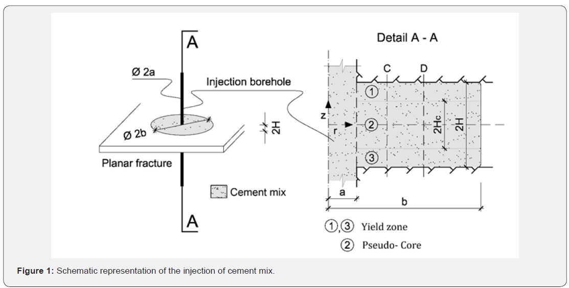
Figure 1 illustrates a schematic representation of the injection of a cement mix in a rock fracture. It is idealized by a viscoplastic material that spreads between two identical, parallel and rigid discs. The injection pressure is noted P. The distance between the discs is noted 2H. The internal radius and front radius of the injected material are noted respectively, a, and b. Their difference, b-a, is the spread. A physical quantitythat is much used in grouting is the spread ratio, noted ξ , and defined with

The core ratio is the ratio of the pseudo-core thickness that is noted 2Hc to the distance between the discs. The core ratio is noted β and is

The core ratio is by definition always bounded by zero and one. The spread ratio is by definition positive. It is rewritten as

Where S is the span that is defined with

It will be proved that for a spreading mix the spread ratio is always smaller than one and the span is an upper bound for the spread.
Flow rate
The main results that are obtained in this note concerning the volumetric flow rate Q and the closing relation with the core ratio and spread ration are the following:
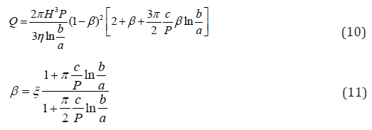
The details that leads to Eq. 10 and 11 are provided in Sec 4. Eq.11 is valid for a spreading mix. It implies that the spread ratio is smaller than the core ratio and by consequence is always smaller than one. This implies that injection will resume from a rest state if the spread ratio is smaller than the core ratio. Hence, the spread ratio of an advancing mix is smaller than one, which implies that the spread, b-a, is smaller than the span, according to Eq.8.
Minimal flow criterion
The main quantities that are monitored during rock fracture grouting are the injection pressure and the volumetric flow rate. These are raw quantities that give a clear indication on the designer’s concern. This particularity should be emphasized when compared to the needs in other disciplines independently from the fact that cement mix is a viscoplastic material. The preoccupation of a designer is to define an attainable objective. This latter is often formulated in term of a minimal spread at a prescribed pressure that is generally the maximal allowable injection pressure [14]. The value of the flow rate at the minimal required spread and the maximal allowable pressure is the flow rate limit. When this limit is attained the injection is generally continued for a while and then stopped. This stop criterion is called the “Minimal Flow Criterion” and is also known under different variants and appellations [15,16] such as “Refusal Pressure”, “Equivalent Lugeon”or “North American Refusal Criterion”.
The closed form that results from Eq.10 and 11 transforms the spread objective into a flow rate objective. This transformation has a practical consequence because it is simpler to monitor the flow rate than the spread. Indeed, when the injection pressure P is maintained constant the flow rate Q is uniquely defined by the spread to the condition that a, c, η and H be known. The injection radius is a standard value unless predefined by the designer. The yield stress and viscosity are selected by the designer, and the aperture of the fracture may be determined from the transmissivity that is obtained by preliminary pressure tests [17]. With that, the value of the flow rate that is calculated at the spread objective with the maximal allowable injection pressure becomes a lower bound. When the flow rate attains the lower bound the injection will be stopped.
Analytic solution
Governing equations
It is supposed that the mix is yielding out with no angular velocity and no angular dependency of the variables. The radial and axial coordinates are noted r and z, and the radial axial velocities v and w. The radial and axial velocities are respectively even and odd functions. They will be sought for positive values of the z axis and extended using their respective parity that is v(r,−z) = v(r, z) and w(r,−z) = −w(r, z) . The shear stress is noted rz τ , and the normal, radial, tangential and axial stresses are τr , τt and τz . The shear and axial stresses are odd functions and the radial and tangential stresses even functions.
The mix satisfies a no-slip condition at the discs,

The pseudo-core is the domain where the shear stress is less than the yield stress and on its boundary

In geotechnical engineering the yield stress is called cohesion that is a more suitable appellation since it does not imply necessarily a transition state.
The governing equations are written in the frame of the lubrication model. A ratio of the distance between the plates to a characteristic length, noted ε , is supposed small and is used to expands the velocities and truncate the governing equations. The truncation and expansion procedure that is followed by Ryan [10] for a 2D slit is extended here to the radial case between rigid parallel discs. The radial component of the velocity is an even function of the axial coordinate and the axial velocity is an off function. The governing equations up to 0(ε 2 ) are

where p is the pressure. It is deduced that the pressure is a function of the radial coordinate only, p=p(r), and the shear stress is τrz = zdp/dr and the core ratio is intimately related to the inverse of the pressure gradient as

The stress and strain-rate relation takes a different form in the boundary layer and pseudo-core. In the boundary layer, the following relations hold

And to zero order expansion, up to 0(ε ) , the velocities are written

The following relations are deduced

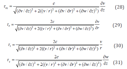
And in the pseudo-core the shear-rate is no more dominant, which needs considering on one hand the normal stresses leading to
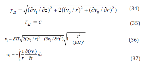
And on the other hand the first order expansion ofthe velocities

In Eq.32, v0 represents the mean value of the radial velocity at the upper and lower edges of the pseudo-core. The mean value of w0 in Eq.33 is zero, and noting that w1 is of the order of εv1 and ε2v0, and that v0 in the pseudo-core is independent of z, the following relations are obtained
Flow rate
The volumetric flow rate is written

Where

In between 0 (−β H,β H),v is 0v (r,β H) in Eq.39 and 40.
Energy balance
The dissipated energy is

Where
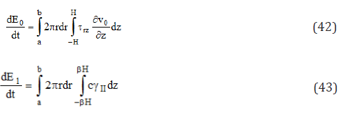
Hence

Final form
A solution is obtained seeking the value of β for which the energy balance is satisfied, that is

This relation is satisfied whenever when

This leads to
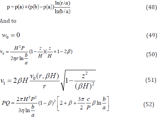

Eq. 10 and 11 are part of the solution. It can be verified that Eq.10 is obtained inserting Eq. 50 and 51 in 39 and 40, and Eq. 11 is obtained equating 52 and 53. P = p(a) − p(b)
The relative difference of the volumetric flow rate and dissipated energy to the values that are obtained with the zero order expansion is practically small.The relative difference of the volumetric flow rate and dissipated energy to the values that are obtained with the zero order expansion is

where the dot over E is its time derivative.
Generally, the ratio c/P in rock fractures grouting is less than one thousand, which is a negligible quantity.Also, c/P is equal to H/S that is the ratioof the fracture half thickness to the span, according to Eq.9. Considering a fracture thickness that is two tenth of a millimeter and a span that is ten meter will give a ratio c/P that is one to ten thousands. The first order expansion does not change significantly the volumetric flow rate and dissipated energy relatively to their values in the frame of the zero order expansion. But, it brings a significant weight to the validity of the solution since it satisfies the mass, momentum and energy equations.
Conclusion
A closed form solution to the radial injection of a cement mix between parallel discs was obtained. It satisfies the mass, momentum and energy equations. It brings a negligible difference to the zero order solution but a big contribution to the completeness of the solution. It can be almost used to calculate the volumetric flow rate into a planar rock fracture and transforms the spread objective into a flow rate objective.
Conflict of interest
The author is a member of the ISRM grouting commission.
References
- Wallner M (1976) Propagation of sedimentation stable cement pastes in jointed rock. Rock Mechanics and Waterways Construction, Publications of the Institute for Foundation Engineering, RWTH Aachen 2: 449-461
- Lapointe R (1997) Contribution à l’étude des méthodes d’injection dans le béton. Mémoire de maîtriseen génie, Mc-Gill, Montréal.
- Gustafsson G, Claesson J, Fransson A (2013) Steering Parameters for Rock Grouting. J Appl Math, p. 9.
- Carter TG, Jefferies MG, Rombough V, Hassler L, Granata R (2017) A Retrospective Evaluation of the Progress of Computer Monitored Grouting. 5th Int. Grouting Conf., Honolulu, ASCE, p. 14.
- Bingham EC (1922) Fluidity and plasticity. McGraw-Hill, New York, pp. 439.
- Prager W (1961) Introduction to mechanics of continua, Dover, pp. 231.
- Dai G, Bird BR (1981) Radial flow of a Bingham fluid between two fixed circular disks, JNNFM, 8: 349-355.
- El Tani M, Stille H (2017) Grout Spread and Injection Period of Silica Solution and Cement Mix in Rock Fractures. Rock Mech and Rock Eng, 50(9): 2365-2380.
- El Tani M (2012) Grouting rock fractures with cement grout. Rock Mech and Rock Eng 45: 547-561.
- Ryan DP (2003) Slow flow of a Bingham fluid in a gap of slowly varying width. Thesis, UBC, p. 71.
- Lipscomb GG, Denn MM (1984) Flow of Bingham fluids in complex geometries. JNNFM 14: 337-346.
- Wilson SDR (1993) Squeezing flow of a Bingham material. JNNFM 47: 211-219.
- Hohenemser K, Prager W (1932) Über die Ansätze der Mechanik isotroper Kontinua. ZAMM 12: 216-226.
- Bonin GR, Rombough VT, Carter TG, Jefferies MG (2012) Towards better injection control and verification of rock grouting, Proc 4th Int Conf Grouting and Deep Mixing, New Orleans, pp. 1460-1471.
- Bruce DA (2011) Rock grouting for dams and the need to fight regressive thinking. Geotech News 29(2): 23-30.
- Bruce DA (2013) Refusal and closure in rock grouting: let’s get it right! Geotech News 31(2):24-25.
- Fransson A, Funehag J, ThörnJ (2016) Swedish grouting design: hydraulic testing and grout selection, Proc Inst Civil Eng. Ground Improvement 169(4): 275-285.


