End Restraints in Single - and Double - Bolted Angles in Lattice Towers
Sriram Kalaga*
Consulting Engineer, Glen Burnie, USA
Submission: April 12, 2018; Published: May 25, 2018
*Corresponding author: Sriram Kalaga, 602 North Shore Drive, Glen Burnie, Maryland 21060, USA, Tel: (410)-439-0897; Email: drkalaga@hotmail.com
How to cite this article: Sriram Kalaga. End Restraints in Single - and Double - Bolted Angles in Lattice Towers. Civil Eng Res J. 2018; 5(2): 555656. DOI: 10.19080/CERJ.2018.05.555656
Abstract
Experimental data on single angle compression members with single- and double-bolt end connection patterns is used to develop adjustment factors for effective buckling lengths. Connection length and clamping effect parameters are proposed and evaluated based on test data. Results from a total of 24 equal leg test angles with single- and double- bolts are used. Slenderness ratios considered ranged from 158 to 312. Angle sizes ranged from 1½” x 1½” x⅛” to 3½” x 3½” x ¼”. Estimated connection lengths were about 12.5% of the member length for single-bolt joints and24.7% for double-bolt joints. Computed effective length factors ranged from 0.753 to 0.875. Results seem to indicate that it is possible to define and calculate connection length of a lattice tower angle member. Suggestions for incorporating connection length issues in routine designs are made.
Keywords: Bolted connections; Buckling capacity; Effective length; Slenderness ratio; Steel angles; Towers
Introduction
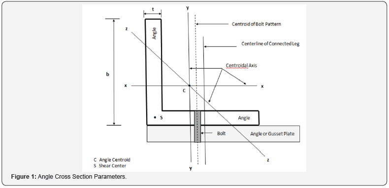
Structural steel angle members are the basic load-carrying elements in electrical transmission towers. These members are usually connected by gusset plates or directly bolted to other members through one leg. Tower joints involve single, double, triple or multiple bolted angles; all bolts are installed snug- tight without any pretension. The buckling or compressive strength of these angles is a function of several parameters: bi-axial eccentricity of the loads (Figure 1), magnitude of restraint provided at the ends, slenderness ratios and pattern of failure either through flexural buckling or combined torsional-flexural buckling [1].

Theoretically, an angle strut is a restrained, eccentricallyandbi- axially loaded, thin-walled beam-column whose buckling strength is governed by end joint stiffness, and thereby, the effective member length for buckling. However, the exact nature of end restraint effects in bolted angle columns is too complex to assess [2]. Previous studies on bolted angles indicate that end connection effects are noticeable even for a single-bolted joint and that end restraints play an important role for members with slenderness ratios over 120 [3]. It was also shown that for slender 2- and 3- bolted angles, test buckling loads are consistently above theoretical values [4].
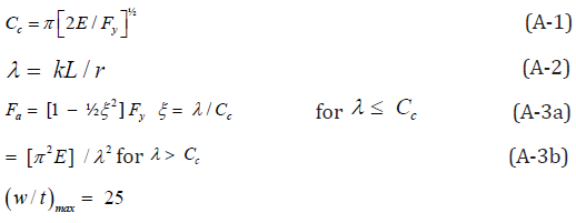
ASCE Standard 10-15 [5] gives the current design procedure for tower angles. It defines effective slenderness in two categories: short columns ( L/r ≤120 ), controlled by eccentricity of loads; and long columns (120 ≤ L/r ≤ 250), controlled by end restraint. (See Notation for definition of parameters). Since the angle is a thin-walled open section, various limits on width-to-thickness ratios of angles are also defined, which in turn control the design compressive stress of the angle column. (See Appendix A for applicable equations).
In general, laboratory tests of angles are focused on determining the failure or buckling load; little effort is directed towards assessing the actual connection length parameter. Part of the difficulty is in defining what exactly constitutes the connection or how far the clamping effect of bolting extends from the bolt(s). One relatively recent study [6] proposed the concept of ‘equivalent reference length’ or ‘characteristic length’ of a connection that allows a comparison of the connection with the connected member. Such knowledge of connection length can help provide a basis for quantifying its translational and rotational stiffness and eventually develop the stiffness matrix of the connection element for inclusion into finite element analysis programs. This paper attempts to address that issue.
The objective of this paper is to:
a. Propose a definition for an angle column connection length including bolt clamping effect for 1- and 2-bolt angles,
b. Utilize test data on single and double bolted angles to derive effective length factors for buckling,
c. Relate the effective length factors to connection lengths,
d. Propose adjustment to ASCE equations for slenderness to give more accurate buckling capacities.
Only elastic buckling of equal-leg single angles with identical end connections is considered in this paper. Residual stresses and initial imperfections, although often important from buckling perspectives, are not considered here.
Connection Length
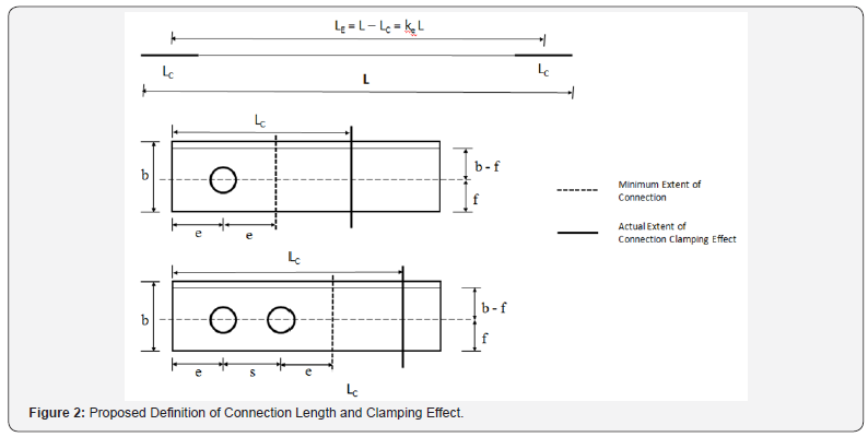
The clamping effect of the bolts in a connection is known to extend over a finite distance from the member end. Figure 2 shows the idealization of connection and its length Lc as proposed in this study and the assumed extent of the clamping zone. Each strut of length L is taken to consist of identical end connections. It is obvious that connection length and the clamping effect increases with number of bolts, thus decreasing the effective member buckling length. The effective beam-column length LE is taken as center-to-center of connections. From Figure 2:.


The parameter Ke is an effective slenderness coefficient which quantifies the influence of connection length Lc and the clamping effect..
A minimum connection length LCM can be also defined just in terms of the end distance ‘e’ and bolt spacing ‘s’.
1-bolt joint 2 LCM = 2e (4)
2-bolt joint 2 LCM = s + 2e (5)
Effective Lengthserimental Study
ASCE 10-15 [5] gives the following equations for effective lengths of lattice tower angles where restraint is the controlling factor for buckling strength rather than eccentricity.
For members unrestrained against rotation at both ends:
kL/r = L/r 120 ≤ L/r ≤ 200 (6)
For members partially restrained against rotation at both ends:
kL/r = 46.2 + 0.615L/r 120 ≤ L/r ≤ 250 (7)
Buckling Capacity
The buckling capacity of an ideal, elastic column is given by the well-known Euler formula:

For a pin-ended column, Equation (8) refers to an effective buckling length of kL = L, k =1.
Defining Test capacity PT in terms of an effective slenderness coefficient Ke:

where I = Ar2
Solving Equation (9) for Ke , we have:

Also, from Equations (8), (9) and (10):

Equation (3) can be used now to determine C L . Equations (10) to (12) facilitate a semi-empirical determination of connection length from test data.
Columns with intermediate-level and full restraint
Traditionally, angles with a single bolt are not considered to provide any rotational restraint [5] and are treated as pin-ended columns. In reality, members with more than one bolt in the end connection scan be considered as those with intermediate level restraint. The effective slenderness coefficient Ke in this case falls in-between those of the pin-ended case and fixed case. Since there are no guidelines to use for 3- bolt situations and beyond, the associated coefficient should be determined empirically from test data. Some previous studies [2] indicate that member behavior approaches that of a fixed-ended column (k≈ 0.50) as the number of bolts in the end connections is increased. It is generally seen that this situation occurs when the joint is fully welded or when the number of bolts approaches 5.
Test Data
Test data on twenty four (24) single, equal-leg angles is selected from published literature [7-9]. The test angles chosen for this study ranged from 1½” x 1½” x ⅛” to 3½” x 3½” x ¼”.Slenderness ratios ranged from 150 to 312 (elastic buckling). Yield strength of steel varied from 36.1ksi (249MPa) to 46.7ksi (322MPa). Bolts used were ⅝” (15.9mm) in diameter with all bolt holes sized 11/16” (17.5mm). All angles were tested in a manner that simulates the actual joint situation in a lattice tower (i.e.) unrestrained rotation in space. The testing setup also ensured that load is applied at an eccentricity as in a real tower. For details of the testing machine, instrumentation, loading process etc. the reader is referred to the paper cited under Reference [5].
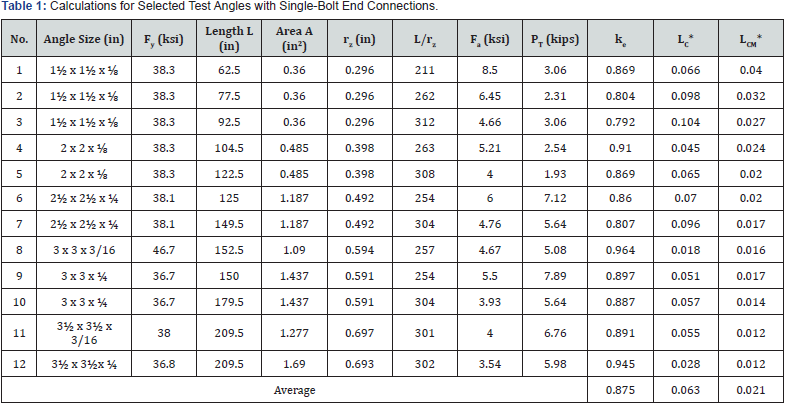
Table 1 & 2 shows the results of calculations for effective slenderness coefficient Ke and connection length LC for one-bolt and two-bolt angles, respectively. The minimum connection length LCM is also calculated and shownin terms of the end distance ‘e’ and bolt spacing ‘s’ of the test specimens. Figure 3 shows the variation of Ke with the number of bolts in the end connection. Assuming fixity to correspond with 5 bolts and Ke = 0.50, the Ke values for 3- and 4-bolt connections are approximately extrapolated to be 0.680 and 0.610, respectively. These two data points are shown with a triangle symbol on the plot.

1 inch = 25.4mm, 1kip = 4.45kN, 1ksi = 6.895MPa
* As a fraction of total length L, at each end
End distance ‘e’ of all specimens = 1¼”
Edge distance ‘f’ of specimens = 13/16” to 1½”

1 inch = 25.4mm, 1 kip = 4.45kN, 1ksi = 6.895MPa
* As a fraction of total length L, at each end
End distance ‘e’ of all specimens = 1¼”
Edge distance ‘f’ of specimens = 13/16” to 1½”
Discussion
As seen in Table 1 & 2, and in Figure 3, the effective slenderness coefficients derived from test results are consistently less than 1.00. As anticipated, the value of Ke decreased as the number of bolts increased. The value obtained for the single-bolt case is 0.875 instead of the usually assumed k =1.0 ; which means, contrary to assumptions that such a joint does not provide any restraint, there is a certain clamping effect associated with the bolt. For the two-bolt case, the Ke value is 0.753 which indicates a larger restraint than that of a single-bolt.

Connection Lengths
Connection lengths LC also proportionately increased as the number of bolts increased. From Tables 1 & 2, it can be seen that the connection lengths derived from test results are consistently non-zero and clearly indicate a clamping effect. The average value obtained for the single-bolt case is 0.125; which means, 12.5% of member length L and indicating a finite clamping effect associated with the bolt. For the two-bolt case, the average LC value is 0.247 or 24.7% of member length L, at each end. This indicates a larger clamping effect than a single-bolt. This observation can be extended to connections with 3 and 4 bolts as well.
In comparison with the minimum connection length LCM defined in terms of end distance and bolt spacing, the actual connection lengths were between 4 to 6 times that of the value of LCM .
Correlation with Design
To verify if the computed effective slenderness coefficients Ke can be used to obtain more accurate design capacities, the parameter is applied to two test angles selected from the set used in this study. The capacity of the two angles (one single-bolted and one double-bolted) is computed using the ASCE 10-15 procedure and then adjusted using the effective slenderness parameter Ke. Appendix B shows the calculations. In both cases, the angles were first assumed as having no restraint at ends (Equation 3a) and then the slenderness is modified with Ke . Results show that the adjusted design capacities are very close to the test loads.
Conclusion
In the preceding sections, a definition for the connection length of an angle beam-column in a lattice tower is proposed where the clamping effect of the bolts is quantified. Test data on single-bolt and double-bolt angles is utilized to develop simple expressions for effective length factors. Connection lengths were determined from the calculated effective slenderness coefficient. The validity of making a simple modification to ASCE design equations using ke is examined.
Although modest, this study showed that it is possible to define and determine connection effects in angle columns in lattice transmission towers using carefully measured test data as a basis. Only a limited number of angle sections and slenderness ratios are studied in this paper. The results reported in this study are by no means exhaustive and further studies are warranted before the concepts discussed here can be generalized. Future investigations may include a larger database of test results, encompassing moreangle sizes, unequal leg angles, slenderness levels, and effects of bolt size and connection geometries. An effort in any of those directions will be a worthwhile undertaking whose goal is to prescribe a more rational basis to the issue of quantifying end restraint effects in transmission towers and thereby more robust designs.
Notation
b = Angle Leg Size
d = Bolt Diameter
e = End Distance
f = Edge Distance
k = Slenderness or Effective Length Coefficient
Ke = Effective Slenderness Coefficient including Connection Length and Clamping Effect
r = Radius of Gyration
rz = Radius of Gyration about axis z-z
s = Bolt Spacing
t = Thickness of Angle Leg
w= Flat Width of Angle Leg including bend radius
A = Area of Cross Section
Cc = As defined
E = Modulus of Elasticity
Fa = Design Compressive Stress
Fu = Specified Tensile Strength of Member
Fy = Steel Yield Stress
I= Moment of Inertia = A*r2
L = Length of the Member
LE = Effective Length including Connection
Lc = Connection Length including Clamping Effect
LCM = Minimum Connection Length
L/r = Slenderness Ratio
PD = Design Compressive Strength
PE = Euler Buckling Load
PT = Test Compression Capacity

ψ = 2.62 for MPa units and 1.0 for ksi units
Appendix A
Design Compressive Stress (based on ASCE 10-15)

 for 262MPa steel, 11.7 for
322MPa steel
 = 23.4 for 262MPa steel, 21.1 for
322MPa steel
Design Compressive Strength =
Appendix B
Example Calculations (based on ASCE 10-15) using Effective Slenderness Coefficient ke
Case 1 One-bolt Angle 64 x 64 x 6.4(2” x 2” x ¼”) Test # 6, Table 1
Fy = 263MPa (38.2 ksi). Assume E = 200GPa (29,000 ksi)
A = 766mm2 (1.19in2)
Width to thickness ratio check:


 = 254 (no restraint at ends)
 Therefore, kL/r>Cc
Apply adjustment for ë with e k computed for single-bolt case.
Revised 
Revised Design Compressive Strength=PD=AFa=30.61kN(6.88kips)
PT = Test capacity = 31.6kN (7.1 kips)
The revised PD containing the effective length factor e k is very close to the test load PT.
Case 2 Two-bolt Angle 76 x 76x 6.4(3” x 3” x ¼”)
Test # 10, Table 2
Fy = 332 MPa (46.7ksi) . Assume E = 200GPa (29,000ksi)
A = 927 mm2 (1.44 in2)
Width to thickness ratio check:

Apply adjustment for ë with ke computed for double-bolt case.

Therefore, kL/r >Cc
Revised 
Revised Design Compressive Strength=PD=A Fa=72.50kN(16.29kips)
PT = Test capacity = 74.7kN (16.8 kips)
The revised PD containing the effective length factor ke is very close to the test load PT .
Note: The effective width of angle ‘w’ used in the w t check includes the fillet radius taken as 2 times t.
Results and References
- Kalaga S (2001) Critical Loads of Restrained Angle Columns. SERC Journal of Structural Engineering 28 (2): 99-103.
- Kalaga S, Adluri SMR (1999) End Restraints in Angle Columns. In: 6th International Conference on Steel and Space Structures, Singapore.
- Bathon L, Mueller HW, Kempner L (1993) Ultimate Load Capacity of Single Steel Angles. ASCE Journal of Structural Engineering 119(1): 279-300.
- Wood AB (1975) Buckling Tests on Crossed Diagonals in Latticed Towers. CIGRE Report 38: 88-99.
- ASCE Standard 10-15 (2015) Design of Latticed Steel Transmission Structures. ASCE, Reston, Virginia, USA.
- Mazzolani F, DeMatteis G, Mandara A (1996) Classification System for Aluminum Alloy Connections. In: IABSE Colloquium on Semi-Rigid Structural Connections, Istanbul, Turkey.
- Stang AH, Strickenberg LR (1922) Results of Some Compression Tests of Structural Steel Angles. Bureau of Standards, US Department of Commerce 16: 651-667.
- AISC (1989) Manual of Steel Construction-Allowable Stress Design. 9th Edition, American Institute of Steel Construction, Chicago, Illinois, USA.
- Madugula MKS, Kennedy JB (1985) Single and Compound Angle Members - Structural Analysis and Design. Elsevier Applied Science Publishers.


