


Elastic and Inelastic Buckling Analysis of Thick Isotropic and Laminated Plates Using Finite Layer Method
Arezoo Samadi Dinani, Mojtaba Azhari*, and Saeid Sarrami Foroushani
Department of Civil Engineering, Isfahan University of Technology, Iran
Submission: August 12, 2017; Published: September 25, 2017
*Correspondence author: Mojtaba Azhari, Department of Civil Engineering, Isfahan University of Technology, Iran, Tel: +98 31 3391 3804; Fax: +98 31 3391 2700; Email: mojtaba@cc.iut.ac.ir
How to cite this article: Nasrin S, Mahmood S B, KavehOstad A A, Saeid E. Assessment of Drainage Slope on the Manning Coarseness coefficient in Mountain Areas. Civil Eng Res J. 2017; 2(4): 555593.DOI: 10.19080/CERJ.2017.02.555593. DOI: 10.19080/CERJ.2017.02.555593
Abstract
In this paper, the elastic and inelastic instability of isotropic and composite thick laminated plates with different end conditions are studied using the finite layer method (FLM). This method is an extension of the well-known finite element method, which efficiently transforms threedimensional problem into one-dimensional because of the trigonometric properties. By assuming appropriate interpolation for in-plane and out-of-plane displacements and using energy approach in conjunction with the assumption of deformation theory for inelastic buckling of each layer, the stiffness and geometry matrices are obtained. Afterward, these matrices are assembled and the eigen value problem is solved to obtain the elastic and inelastic critical buckling load. Numerical results are presented to demonstrate the accuracy and efficiency of the method.
Keywords: Thick Plate; Elastic Buckling; Inelastic Buckling; Finite layer method
Introduction
Plates are often utilized in the situations which are probable to be subjected to in-plane compressive loading. Therefore, the buckling is a very probable phenomenon in which the plate experiences large deformation while the stresses are not considerable. Thus, it can be critical and the accurate buckling solution is inevitable. According to the width to thickness ratio of the plate, it may undergo elastic or inelastic buckling. In the plates with low width to thickness ratio, the inelastic buckling may occur, while the elastic buckling is more probable in the plates with high width to thickness ratio. In the recent years, thick laminated composite plates are increasingly used in various branches of engineering and industrial products such as building structures, aerospace, aircraft, marine, and so on. This is due to their high strength and stiffness, low weight, excellent resistance to corrosion, low thermal expansion and satisfactory durability under fatigue loading.
Composite materials are obtained by combining two or more materials in the microscopic scale. Laminated plates are made of several individual layers, in each of which the fibers are oriented in a specific direction to provide required strength and stiffness parameters efficiently. The elastic and inelastic buckling of plates has been investigated by many researchers using different methods and theories. Among the theories applied for the buckling analysis of the laminated plates, it is the classical laminated plate theory which is an extension of Kirchhoff or classical plate theory (CPT) to laminated composite plates. This theory assumes that the planes normal to the mid-surface remains straight and normal to mid-surface after deformation. This theory neglects the transverse shear stresses and usually underestimates deflections, while overestimates the buckling loads and natural frequencies of thick and moderately thick laminated composite plates. Consequently, the CPT is not applicable for the analysis of moderately thick laminated composite plates [1-3].
Another group of theories are shear deformation theories, first of which is the first-order shear deformation theory (FSDT) which assumes uniform transverse shear stress through the thickness of the plate. The FSDT requires a shear correction factor to produce accurate results. It is important to note that because some parameters such as geometry, lamination, loading type and boundary conditions affect the determination of shear correction factor, it is not easy to determine its exact value [4-6]. To avoid the shortcoming of the first-order shear deformation theory, Reddy developed the higher order shear deformation theory [7,8] in which there is no need to use shear correction factor. This theory assumes parabolic distribution of transverse shear strains throughout the thickness which satisfies the transverse shear-free surface conditions. Accordingly, this theory provides more accurate results for thick laminated plates [9-11].
Among the available researches about the numerical solutions of thick plate buckling problem, the finite layer method (FLM) has been found to be particularly appropriate for this type of problems and proved to have good efficiency and accuracy. The finite layer method was first applied by Cheung and Chakrabarti for the static analysis of simply supported thick laminated plates [12]. Cheung et al. [13] studied the buckling of sandwich plates by FLM. Using this method, Cheung et al. [14] investigated the free vibration of thick laminated rectangular plates. Based on the Reissner's mixed variational theorem (RMVT), Wu & Li [15,16] developed unified formulations of the RMVT-based finite layer methods for the static, vibration, and stability analyses of simply supported, multilayered functionally graded elastic plates and laminated composite ones. This method is also used and developed by Timonin [17-20] to analyze the interlaminar stresses and delamination of laminated plates as well as their bending and twisting behaviors.

The finite layer method may be considered as an extension of the finite element method which enables a full three-dimensional analysis. FLM considers the transverse shear stiffness, thus the results are more accurate for elastic and inelastic buckling analysis of thick plates. In this paper, the elastic and inelastic buckling of plates with different boundary conditions is studied using the finite layer method. To this end, the plate behavior is modeled as shown in the Figure 1. In this figure kb and ks represent the flexural and shear stiffness, respectively. According to the Figure 1, ke which represents the equivalent plate stiffness, is expressed as:
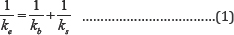
It should be noted that in the classical plate theory ks is neglected which means that ks = ∞, thus the equivalent stiffness is equal to the flexural stiffness (ke = kb) . However, for the thick laminated plates, neglecting ks overestimates the buckling load; therefore, both ks and kb should be considered to obtain accurate results. Due to the fact that thick plates are usually prone to experience inelastic buckling, the FLM formulation is extended to consider the plasticity effects using different theories. Moreover, due to plasticity effects, kb and ks decrease in the inelastic range. Therefore, by considering the shear and plasticity effects, the equivalent plate stiffness decreases. Deformation and flow theories are used for inelastic buckling problems and the buckling behavior is sensitive to the selected theory. The deformation theory is used by Stowell [21], Ilyushin [22] & Bijlaard [23], while Handleman & Prager [24] used the flow theory. The researches have shown that in comparison with the flow theory, the deformation theory gives more accurate results for inelastic plate buckling.
The Inelastic buckling of simply supported plates using the finite element method is studied by Pifko & Isakson [25]. To solve this problem, Lau and Hancock used the Spline finite strip method [26]. In addition, Azhari & Bradford [27,28] studied the inelastic buckling of plates and plate assemblies. For solving the inelastic buckling of thick plates by means of the finite layer method, the three-dimensional formulation is needed to achieve accurate results. This is due to the nature and formulation of the theory. Moreover, the deformation theory and Ramberg-Osgood representation of the stress-strain curve is employed in this study.
This paper is organized into the following sections. In section 2, the finite layer method is overviewed and mathematical formulation of the problem for the buckling analysis of thick plates in the elastic and inelastic region is presented. In section 3, numerical results and discussions are presented to show the implementation of the model for analysis of thick plates with different geometries. Finally, some concluding remarks are presented in section 4.
Finite Layer Method
General finite layer method:

In the finite layer method, the plate is divided by one or more finite layers. The plate and one of its finite layers are shown in Figure 2. The axis of the coordinate system, x, y and z, are selected as shown in the figure while the surface of the plate (axb) is parallel to the xy plane and z shows the direction of the plate thickness (h). As shown in Figure 2. u, v and w are the displacement components of the plate along x,y and z directions, respectively. Moreover, c is the thickness of each layer.
Displacement functions
Depending on the boundary conditions of the plate, different trigonometric functions are used for the in-plane interpolation of displacement field. On the other hand, polynomial functions are employed in the thickness direction. In this study, the second order polynomials are used to achieve more accuracy. The displacement functions of each layer may be written as:
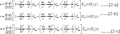
Where r and s represent the number of harmonics used in x and y directions, respectively. uimn , vmni and wimn (i = 1, 2, 3) denote the corresponding nodal displacement parameters in the thickness of each layer (see Figure 2b).wimn and Yn(y) which are listed in Appendix I, are the eigen functions satisfying the boundary conditions in the x and y directions, respectively; besides, X'm(x) and Y'n(y) are their first derivatives. Equations. (2-a) to (2-c) can be rewritten for each layer in the matrix form as:
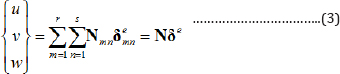
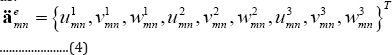
in the Equation (3], Nmn a 3 x 9 matrix which contains the shape functions corresponding to the(m,n)th mode, while  is the corresponding nodal displacement vector and is expressed as:
Stress-strain relations
In the following sub-sections the stress-strain relations for both elastic and inelastic range are presented.
Stress-strain relations for elastic buckling: In the elastic buckling the stress-strain relations in the principal coordinate system for each layer can be stated as:
Where εlayer and σlayer are strains and stresses in the principal coordinate system of each layer. Also  is defined by the properties of each layer as follows:
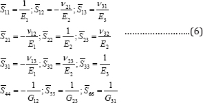
Where E1, E2 and E3 are the moduli of elasticity or Young's modulus in 1, 2 and 3 principal directions ofthe layer, respectively; G12, G23, and G31 are the shear modul in the 12, 23, and 31 planes,respectively; and finally, Vij represents the Poisson's ratio and is equal to εj/ εi, when the material is subjected to σi It should be noted that the moduli of elasticity and Poisson's ratios are not independent and are related by vijEj = vijEi.
Stress-strain relations for inelastic buckling: In the inelastic buckling the stress-strain relations for each layer may be expressed as [29]:

In Equation (7) the matrix H -considers inelasticity in the stress-strain relations and is presented in Appendix II.
Strain-displacement relations
The following relations between the strains and displacements are used in the analysis of both elastic and inelastic buckling analysis [1]. First, the strain vector, s, is defined as:

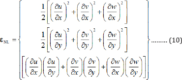
in which,εL contains the linear terms of the strains σ0.7 and εL contains the nonlinear flexural strains, may be written as:
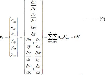
where, Bmn is a 6 x 9 matrix and is called the strain matrix mn of the (m, n)th term. This matrix is obtained by proper derivation of u, v and w which are defined in terms of shape functions in Equation (3].εNL is also defined as:
Stiffness and geometry matrices
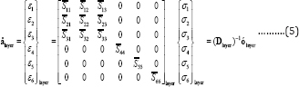
The stress-strain relations in the global coordinate system for each layer can be stated as:
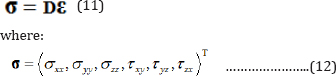
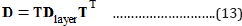
ε and σ are the strains and stress vectors in the global coordinate system of each layer. σ is the generalized elastic matrix, which is obtained from the elasticity matrix in the fiber- fixed local coordinate transformation. The transformed material stiffness matrix is given by:
In which Dlayer is the elastic matrix in the material coordinate system. T is the transformation matrix and is defined in Equation (14):
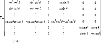
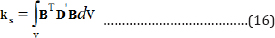
where the angle θ is measured from the x-axis of the reference coordinate to the 1-axis of the material principle coordinate. After assuming the displacement functions and using energy approach, the stiffness and geometry matrices are obtained for each layer. The strain energy U is given by:
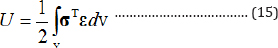
By using Equation (15) and some mathematical manipulations in the stiffness matrix of each layer, can be obtained by:
D' in Equation is a matrix consists of a set of D matrices corresponding to (m, n)th mode.
Moreover, the potential energy for each layer can be expressed as:
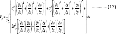
Where σ0x and σ0y are the in-plane compressive stresses and σ0xy is the shear stress acting on the edges of the plate.
The first derivatives of u, v and w may be expressed as:
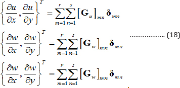
Where  are each 2x9 matrices and obtained after proper derivation of Equation (2).
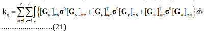
Applying Equation (18) to Equation (17), the potential energy can be rewritten in the matrix form as:
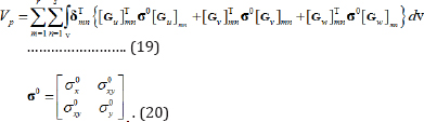
Therefore, the stability matrix for each layer, , is given by:
Critical elastic buckling load
Afterward, by assembling the stiffness and the stability matrices of all layers of the plate, λ the eigenvalue equation for buckling of plates may be obtained as:

in which Ks and KG are the global stiffness and geometry matrices of the whole laminated plate, Δ is the critical buckling load, λ and the eigenvector is the global displacement vector of the system.
The eigenvalue equation in the elastic buckling can be solved for the critical buckling load of the plate. By setting the determinant of the left hand term of Equation (22) to zero, the critical buckling load, , for the elastic buckling will be derived.
Critical elastic buckling load
For the inelastic buckling analysis, by assuming the stress value and solving the eigenvalue problem of Equation (22), the value of λ will be determined. If λ = 1 , the assumed stress will be the critical stress of buckling, otherwise, we should try another stress value to obtain the critical inelastic buckling stress.
Numerical results
Numerical results are presented to demonstrate the accuracy and efficiency of the present method. Based on the finite layer formulation developed in the previous section, computer programs are developed in the MATLAB environment to study the elastic and inelastic buckling of plates.
Elastic buckling
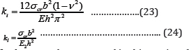
The elastic buckling results include both isotropic and laminated composite plates. For the elastic buckling, the critical stress obtained from the eigenvalue problem is normalized in terms of local buckling coefficient by Eqs. (23) and (24). In these equations, ki indicates the local buckling coefficient for the isotropic plates, where kl represents the local buckling coefficient of laminated composite plates.
In the examples presented in this section, (except for section 4.1.3) the Poisson's ratio of the isotropic plates is assumed 0.3 and the properties of the cross-ply laminated composite plates with the layer orientation of (0°/90o/90o/0°) are as below:


Convergence study: As the results of the FLM depend on the number of layers, a convergence study is carried out for isotropic plates with all edges simply supported. The plate is subjected to uni-axial uniform compression loading and the width to thickness ratio is assumed 10. The results obtained by the finite layer method developed herein are given in Table 1.Table 1 shows the convergence pattern for the elastic local buckling coefficients, ki, by dividing the plate into different numbers of layers. It is shown that the accurate results are obtained by using twelve layers. It should be noted that required number of harmonic terms, r and s, to obtain accurate results are different depending on the aspect ratio of the plate. Figure 3 shows the variation of local buckling coefficient vs. aspect ratio for different values of r and s. It is shown that by increasing the aspect ratio, more harmonic terms should be employed to get accurate results.


Local buckling of isotropic plates with simply supported conditions under uni-axial compressive load and different boundary conditions under uni-axial load: The local buckling width to thickness ratios are computed using the proposed coefficients of isotropic plates with simply supported boundary finite layer method and are presented in Table 2. The results are compared with those obtained by Reddy using the higher-order shear deformation theory [7]. As shown in Table 2, the present results and Reddy results are in good agreement for moderately thick plates, but for thick plates there is difference between the results. The difference is because Reddy has used higher order shear deformation theory which is not able to perfectly model the shear stiffness of thick plates and therefore leads to get larger local buckling coefficients.
Local buckling of square laminated composite plates with simply supported boundary conditions under uni-axial load: Akhras et al. [30] employed the finite strip method to study local buckling of thick simply supported laminated composite plates according to the higher-order shear deformation theory. Reddy [7] also used the higher-order shear deformation theory to this end. The layer orientations are assumed as (0°/90°), (0°/90°/0°), and (0°/90°/90°/0°). The material properties of orthotropic laminates are taken as:


Table 3 presents the results of local buckling coefficient, kl , using the FLM. As the Table 3 shows, the results are in good agreement with those obtained by Reddy [7] & Akhras et al. [30] for plates possessing the width to thickness ratios greater than 10; however, the local buckling coefficient of thick plates with aspect ratios less than 10, show some discrepancies due to the effects of the shear deformations.


Thickness effect on the local buckling coefficient: Figures 4 and 5 illustrate the thickness effect on the local buckling coefficient of the isotropic and laminated composite plates. As Figure 4 shows, the local buckling coefficient of isotropic plates decreases when the thickness of the plate increases. For the laminated composite plates, the thickness effect is the same as isotropic plates. It means that by decreasing the width to thickness ratio, the local buckling coefficient decreases.


Loading effects on local buckling coefficient: The loading effect on the local buckling coefficient of isotropic and laminated (0°/90°/90°/0°) composite plates with the width to thickness ratio of 10 and different values of aspect ratios, is studied and the results are shown in Figures 6 & 7. The plate is under uniform and equal compressive loading on both edges. It could be seen from Figures 6 & 7 that the local buckling coefficient is larger when the plate is under uni-axial loading, rather than when it is under bi-axial one. For example, in the case of square plates, the local buckling coefficient of uni-axial loading is twice of the bi-axial loading.
The effect of boundary conditions on the local buckling coefficient: The effect of boundary conditions on the local buckling coefficient of the plate under uni-axial loading is studied in this section. Loaded edges are assumed to be one of these three types: both simply supported (S), simply supported- clamped (SC) and both clamped (C). On the other hands, the load free edges conditions may be both simply supported (S), simply supported-clamped (SC) and both clamped (C). The stiffer boundary conditions leads to larger local buckling coefficient. Figures 8 & 9 show the effects of boundary conditions on the buckling load of isotropic and laminated (0°/90°/90°/0°) composite plates with b/h = 10 and under uni-axial loading. According to Figures 8 & 9, the plates with all edges clamped have the largest local buckling coefficient, while the minimum values belong to the all edges simply supported plates.


Inelastic buckling
Thick plates usually are prone to buckle in the inelastic range. In the present study, finite layer method is used to enable a full three-dimensional analysis for inelastic buckling of thick plates which leads to more accurate results. This study is also based on Ramberg-Osgood representation of the stress-strain curve using the deformation theory of plasticity. The tangent and secant moduli, Et and Es, are expressed respectively as [25]:
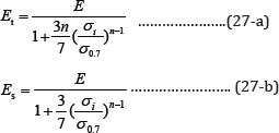
Where n is a shape parameter given in [25], E is the slope of the linear portion of the stress-strain curve, σi is the effective stress [25], and σo.7 is the effective stress at which the curve has secant moduli of 0.7E.


Inelastic buckling analysis of simply supported rectangular plates: The buckling stresses of simply supported rectangular plates are computed in this section by the finite layer method. The results are presented in Tables 4-6, and compared with those of Isakson & Pifko [25] and Azhari & Bradford [27]. Isakson & Pifko [25] studied the inelastic buckling of simply supported plates by finite element method, while Azhari & Bradford [27] used the complex finite strip method to achieve the results. The material properties assumed in this section are as:

As shown in Tables 4-6, the results obtained by the FLM are less than those reported in [25,27]. These references use the classical plate theory in their analysis which neglects the shear effects and overestimates the stiffness of the plate. This assumption is not valid in the analysis of inelastic buckling of thick plates [28,29]. The present formulation considers transverse shear stiffness and enables a more actual analysis of thick plates. By this explanation, it could be concluded that the differences between the present results and those obtained by Isakson and Piko and Azhari and Bradford are reasonable.
Thickness effect on the inelastic buckling: Similar to the section 3.1, the plastic local buckling coefficient is defined as:
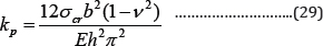

Table 7 shows the values of kp for a square, all edges simply supported aluminum plate with different width to thickness ratios. The plate is assumed to be under uni-axial compressive load. Comparing Tables 2 & 7, one could conclude that the local buckling coefficients in both elastic and plastic cases are the same for thin plates, while this is not true for thick plates because of the reductive effects of the plastic rigidity. Moreover, the effect of thickness on the inelastic buckling of the plates under uniaxial and bi-axial compressive loading is shown in Figures 10 &11,respectively. It is shown in both figures that by decreasing the thickness of the plate, the inelastic critical buckling stress decreases [30,31].


Conclusion
The finite layer method is used in this study to analyze the elastic and inelastic buckling of thick plates. This method enables a full three-dimensional analysis of the plates in which the transverse shear stiffness is considered; therefore, the accurate results can be obtained for elastic and inelastic buckling of thick plates. The finite layer method is also applied for both isotropic and laminated composite plates. The numerical studies show that the results are in good agreement with those obtained in available references. Moreover, the present method is economical and simple to program, it also saves time and reduces the computational cost as well as storage requirement.
References
- Reddy JN (1997) Mechanics of laminated composite plates: theory and analysis. (2nd edn), CRC press, Florida, USA.
- Whitney J (1969) The effect of transverse shear deformation on the bending of laminated plates. Journal of Composite Materials 3(3): 534547.
- Whitney J, Pagano N (1970) Shear deformation in heterogeneous anisotropic plates. Journal of Applied Mechanics 37(4): 1031-1036.
- Akhras G, Cheung MS, Li W (1993) Static and vibration analysis of anisotropic composite laminates by finite strip method. International Journal of Solids and Structures 30(22): 3129-3137.
- Cheung MS, Akhras G, Li W(1993) Stability analysis of anisotropic laminated composite plates by finite strip method. Computers & structures 49(6): 963-967.
- Hinton E (1977) Flexure of composite laminates using the thick finite strip method. Computers & structures 7(2): 217-220.
- Reddy JN, Phan N (1985) Stability and vibration of isotropic,orthotropic and laminated plates according to a higher-order shear deformation theory. Journal of sound and vibration 98(2): 157-170.
- Reddy JN (1984) A simple higher-order theory for laminated composite plates. Journal of Applied Mechanics 51(4): 745-752.
- Akhras G, Cheung MS, Li W (1994) Finite strip analysis of anisotropic laminated composite plates using higher-order shear deformation theory. Computers & structures 52(3): 471-477.
- Dawe D (2002) Use of the finite strip method in predicting the behaviour of composite laminated structures. Composite Structures 57(1): 11-36.
- Zhang Y, Wang S, Loughlan J (2006) Free vibration analysis of rectangular composite laminates using a layerwise cubic B-spline finite strip method. Thin-walled structures 44(6): 601-622.
- Cheung Y, Chakrabarti S (1971) Analysis of simply supported thick, layered plates. Journal of the Engineering Mechanics Division 97(3): 1039-1044.
- Cheung Y, Tham L, Chong K (1982) Buckling of sandwich plate by finite layer method. Computers & structures 15 (2): 131-134.
- Cheung Y, Chakrabarti S (1972) Free vibration of thick, layered rectangular plates by a finite layer method. Journal of sound and vibration 21(3): 277-284.
- Wu CP, Li HY (2010) RMVT-and PVD-Based Finite Layer Methods for the Quasi-3D Free Vibration Analysis of Multilayered Composite and FGM Plates. CMC: Computers, Materials & Continua 19(2): 155-198.
- Wu CP, Li HY (2010) The RMVT-and PVD-based finite layer methods for the three-dimensional analysis of multilayered composite and FGM plates. Composite Structures 92(10): 2476-2496.
- Timonin AM (2013) Finite-Layer Method: a UniFied approach to a nUMericaL anaLysis oF interLaMinar stresses, Large deFLections, and deLaMination stabiLity oF coMposites part 1 Linear behavior Mechanics of Composite Materials 49(3): 231-244.
- Timonin AM (2013) Finite-layer method: a unified approach to a numerical analysis of interlaminar stresses, large deflections, and delamination stability of composites. Part 2. Nonlinear behavior. Mech. Compos. Mater 49(4): 369-380.
- Timonin AM (2014) Finite-layer method: a unified approach to a numerical analysis of interlaminar stresses, large deflections, and delamination stability of composites. Part 3. Stability. Mechanics of Composite Materials 50 (2): 187-196.
- Timonin AM (2016) Finite-Layer Method: Bending and Twisting of Laminated Plates with Delaminations. Mechanics of Composite Materials 52(1): 55-72.
- Stowell EZ (1948) A unified theory of plastic buckling of columns and plates. USA.
- Ilyushin A (1947) The elasto-plastic stability of plates. USA.
- Bijlaard PP (1949) Theory and tests on the plastic stability of plates and shells. Journal of the Aeronautical Sciences 16 (9): 529-541.
- Handelman G, Prager W (1949) Plastic buckling of a rectangular plate under edge thrusts. USA.
- Isakson G, Pifko A (1969) A finite-element method for the plastic buckling analysis of plates. AIAA Journal 7(10): 1950-1957.
- Lau SCW, Hancock GJ (1989) Inelastic buckling analyses of beams, columns and plates using the spline finite strip method. Thin-walled structures 7(3-4): 213-238.
- Azhari M, Bradford MA (1993) Inelastic initial local buckling of plates with and without residual stresses. Engineering Structures 15(1): 3139.
- Bradford M, Azhari M (1995) Inelastic local buckling of plates and plate assemblies using bubble functions. Engineering Structures 17(2): 95103.
- Chen WF, Han DJ (2007) Plasticity for structural engineers. J Ross Publishing, Pine Island, USA.
- Akhras G, CheungMS, Li W (1995) Vibration and stability analyses of thick anisotropic composite plates by finite strip method. Structural Engineering and Mechanics 3(1): 49-60.
- Bradford MA, Azhari M (1995) Buckling of plates with different end conditions using the finite strip method. Computers & structures 56(1): 75-83.


