


Shear Deformation and the Buckling of Columns, Revisited
James M Kelly*
University of California, USA
Submission: August 15, 2017; Published: September 20, 2017
*Corresponding author: James M. Kelly, professor emeritus of civil engineering, university of California, berkeley, PEER UC Berkeley, 1301 South 46th. Street, Richmond, CA 94804-4698, USA, Tel: 510-665-3470; Email: jmkelly@berkeley.edu
How to cite this article: James M K. Shear Deformation and the Buckling of Columns, Revisited. Civil Eng Res J. 2017; 2(1): 555579. DOI: 10.19080/CERJ.2017.02.555579
Abstract
The question of the correct approach to analyze the buckling of columns in which shear deformation is important continues to be a matter of some uncertainty. There are few textbooks that treat this problem definitively. Most describe one solution or another, with the statement that they do not differ very much in practice. However there are situations where different theories can result in very different predictions; this paper explains why. It will be shown that the prediction of buckling loads for columns that are very weak in shear is crucially dependent on the choice of the direction for the axial load of the column in the buckled configuration. Examples of three separate selections for the axial load direction will be shown to lead to very different predictions of the buckling load. The results can differ by orders of magnitude. Note: these predictions are all valid but the type of columns must be taken into consideration.
Editorial
There are many circumstances where the effect of shear deformation on the buckling of columns needs to be included. The problem appears to have been first studied by Engesser [1,2], with the purpose of estimating the buckling load of built-up columns. The Engesser result has been described in many textbooks as the approach to be used for shear-sensitive columns (e.g., timoshenko & Gere [3], and Simitses [4], with the interesting result that the critical load can be expressed in terms of the shear stiffness per unit length GA, denoted by PS , and the euler load of the shear rigid column PE by

Thus the critical load is bounded above by both and . The Engesser formula appears to work well for built-up columns and also for beams of sandwich construction. It was rederived for sandwich beams by plantema [5], apparently without knowledge of the work of Engesser since it is not referenced in his work. plantema was the first to express the solution in the above form there are, however, situations where the Engesser formula is excessively conservative in the prediction of the buckling load. An alternative formulation of the buckling problem was developed by Haringx [6] in a series of reports published by the phillips research institute in holland over the years 1947-49. The purpose of this research was to predict the mechanical behavior of springs-helical steel and elastomeric-to be used as vibration isolators for electrical equipment. In the Haringx formulation, the buckling load for very weak shear is

It is clear that for weak shear columns where PS is very much less than PE, there will be a very large difference between the predictions of the two theories. On the other hand, when Ps is much larger than pE , both approaches give the same result; most textbooks have tended to ignore the Haringx solution or include it without explanation as an alternative but essentially similar solution.
In this paper i will use three different models to demonstrate how they differ and in what situations they are applicable: case 1 will be of the Engesser type, case 2 the Haringx type, and case 3 a model between the two. The solutions will be done using equilibrium analysis and linear material models in order to emphasize the physical underpinning of the theories.
Equations of Shear Deformation in Beams
In this paper we will restrict attention to rectangular beams with the cross-section dimensions of widthb ,depth h and length l (although the theory could also be applied to beams of arbitrary symmetric cross section with some increase in algebraic complexity). The kinematic variables used to describe the deformation, all functions of coordinate x directed along the axis of the beam 0 ≤ x≤ l are . u, v, ψ, and ø In terms of these, the displacement field, as functions of and are
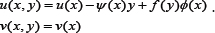
The function f(y) is chosen to be orthogonal to both 1 and -h /2≤ y ≤ h /2on , and the function selected is


Thus u represents the displacement of the middle surface in the x -direction, v the deflection in the y -direction, is the average rotation of a section normal to the un-deformed middle surface, and ψ is a measureø of the warping of the originally plane section Figure 1.
The resulting strains are
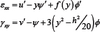
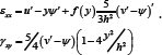
Per Tsai & Kelly [7], at this stage the warping function could be retained as an independent kinematic variable, but for this analysis we select ø; such that γxy = 0 at y = ±h/2 , leading to
The stresses are assumed to be σxx = Eεxx and τxy = Gγxy ,and stress resultants N and V are defined by
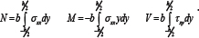
Following these integrations the basic constitutive equations

Because the intention here is to solve buckling equations for the different examples simultaneously the equation above will be rewritten as

For example, for the sandwich beam, thegas is the area of the core times the shear modulus of the core material; for an elastomeric bearing the GA is modified according to the ratio of the total height to the total thickness of rubber; and for the warped section it is 5/6GA. The bending stiffness,El , is similarly modified for the three types as needed.
Equilibrium in the Buckled Configuration
The effect of the axial load depends critically on the assumption of the direction of the resultant axial the axial load depends critically on the assumption of the direction of the resultant axial load, denoted here by N .there are three choices. Namely:

a. Case (1): Axial load parallel to the deformed middle surface (or external surfaces, top and bottom); see Figure 2.

b. Case (2): Axial load perpendicular to the rotated face at x; see Figure 3.

c. Case (3): Axial stress distributed normal to the warped surface; see Figure 4.
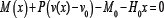
In each case the equation of moment equilibrium taken about the displaced point at x and y = 0 is
For case (1), resolving forces perpendicular to v' gives
V (x )-Pv' + H0 = 0
And parallel to ψ in case (2) gives
V(x)-pψ+H0=0
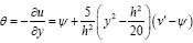
For case (3) It is useful to introduce 6 the local rotation of a line element at a point on the warped surface perpendicular to the surface, as shown in Figure 4. This is given by
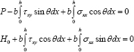
Equilibrium in the x - and y-directions separately leads to
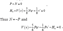
Taking cos θ = 1, sin θ = 6 and neglecting products and squares of v', φ, θ leads to P + N = 0
We can write all of these shear equilibrium equations as one equation:
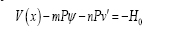
Where for case (1) m = 0, n = 1, for case (2) m = 1, n = 0 , and for case (3)
Buckling Equations
Substitution of stress resultants in terms of the kinematic variables leads to the following two equations
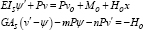
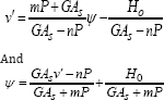
These equations are coupled in the sense that v and ψ appear in both, but they can be uncoupled by solving the second for in terms of ψ and then for ψ in terms of , giving
Substituting these into the first equilibrium equation gives two uncoupled equations for and in the form
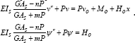
Thus the two equations to be solved for the two kinematic variables have the same form but with different right hand sides. The most general solutions of these equations are
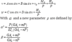
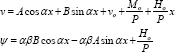
Of course the constants A, B, C, and D are not independent of each other but are connected by the relations derived from the shear equilibrium equation. We find that C = αβB and D = αβA , giving the most general solution of the system in the form
Buckling Loads for Example Columns
There are two problems of immediate interest in applying these results: they are the simply supported column of lengthl for which the boundary conditions are
v ( 0) = V0 = 0, H ( 0) = 0
ψ( 0) = 0, ψ(l ) = 0
And the fixed-floating column (characterized by the isolation bearing) for which
v (0 ) = v = 0, v (l ) = 0 .
M0 = 0, H (0) = 0
For both of these examples the boundary conditions require that
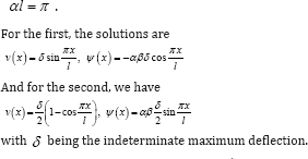
The result αl = π means that and in turn this means that
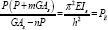
Where PE is the Euler load for a regular column. If we denote GAS by PS , the above equation for the buckling load becomes
mP2 + PPS + nPPE - PSPE = 0 .
It is useful to normalize this equation by defining p = P/PE and λ = PS/PE , giving the equation for the buckling load, in the form
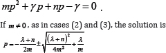
mp2 +γp + np-γ = 0 .
If m ≠ 0, as in cases (2) and (S), the solution is
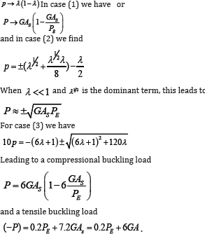
When m=0 and n=1 , as in case (1), we have only the single solution:

Regular beam theory is defined by GAS→∞or λ>>1 ; for case (1) this leads to

For cases (2) and (3) we have the same result if the shear tends to infinity; but if the shear is very weak, the situation when λ << 1, the results for the three cases are very different.

To illustrate the differences between the three solutions,it is interesting to plot them over a narrow range of λ from 0 to 2, as shown in Figure 5, and wide range of λ using a linear-logarithmic plot, as shown in Figure 6.

Downward Displacement of Top of Column
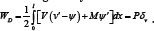
To demonstrate the cause of the differences between the three types of column, we compute the downward displacement of the top of the column by using the work-energy balance. When the column buckles, the top of the column moves downward and the buckling load remains constant. During this process, the energy stored in the column is balanced by the work done by the buckling load. We denote the energy stored by WD and work done byPδv where δv is the downward displacement of the top. The equilibrium equations for each case are then used to derive the appropriate formula for the displacement. the balance of energy and work is given by
For columns of type case (1), the equilibrium equations are V = PV' and M = -Pv , which when substituted into the equation leads to
Since the second term in the integral when integrated vanishes, we have

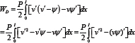
For case (2), we use the formulation due to Haringx, and the equilibrium equations are V = Pψ and M = -Pv , giving leading to
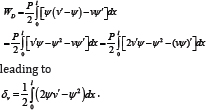
However we also have γxy = v'-ψ, which can be used to replace ψ in terms of γ,xy in the above equation, leading to

This shows that in this case the shear acts to reduce the downward movement, requiring ha larger buckling load than for case (1).a similar derivation can be made for the section with warping, but since the shear strain varies across the section the inference is less clear, will not be included here.
Possibility of Tension Buckling
Note that for both cases (2) and (3), the additional solutions for the buckling load imply the presence of a buckling load that is tensile. In the case of the Haringx model, the tensile buckling load-see Kelly [8] -is almost the same as the compressive buckling load, i.e., the tension load is larger than the compressive load by PS , which is considered as negligible in comparison with P ). Thus applying the Haringx model to elastomeric bearings is not appropriate due to the phenomenon of cavitation in rubber under tension, but there may be other situations where Haringx is an appropriate model, and the tensile buckling could be an importent aspect of behavior.

In case (3) the warping does permit tensile buckling, but in contrast to case (2), the difference between them is large, and tensile buckling may be impossible to achieve. as λ→0 , the compression buckling load goes to zero but the tensile buckling load at λ = 0 is 0.2PE , which for small values of shear stiffness is a very large load compared to the compression load; see Figure 7.
Conclusion
It has been shown that the prediction of buckling loads for columns that are very weak in shear is crucially dependent on the choice of the direction for the axial load of the column in the buckled configuration. Numerical analysis of three separate selections for the axial load direction have been shown to lead to very different predictions of the buckling load. The results in the three examples differ by orders of magnitude. Note: these predictions are all valid but the type of columns must be taken into consideration.
References
- Engesser F (1889) Ueber die knickfestigkeitgeraderstabe. zeitschriftfurarchitektur und ingenieurwesen 35(4): 455-462.
- Engesser F (1891) Die knickfestigkeitgeraderstabe. zentralblatt der bauverwaltung 11: 483-486.
- Timoshenko SP, Gere JM (1961) Theory of elastic stability. McGraw- hill, New York, USA, p. 541.
- Simitses GJ (1976) An introduction to the elastic stability of structures. Prentice-hall, New York, USA, p. 253.
- Plantema FJ (1966) Sandwich construction. John wiley & sons Inc, New York, USA.
- Haringx JA (1949) On highly compressible helical springs and rubber rods, and their application for vibration-free mountingsiii. Philips research reports no 4: 206-220.
- Tsai HC, Kelly JM (2005) buckling of short beams with warping effect included. International journal of solids and structures 42: 239-253.
- Kelly JM (2003) Tension buckling in multilayer elastomeric bearings ASCE. Journal of engineering mechanics 129(12): 1363-1368.


