A Novel Method of Quantifying Mandibular Asymmetry
Sombir Singh1, Shagun Sharma2, Karen Raju3 and Harish Kumar Banga4
1MDS Orthodontic, Director new way Orthodontic, India
2Centre of excellence in Industrial & Product Design, Punjab Engineering College, Sector-12, Chandigarh, India
3Associate Specialist, University of California, San Francisco, USA
4Department of Fashion & Lifestyle Accessory Design, National Institute of Fashion Technology, Mumbai, India
Submission: March 23, 2023; Published: April 05, 2022
*Corresponding author: Sombir Singh, MDS Orthodontic, Director new way Orthodontic, India
How to cite this article: Sombir S, Shagun S, Karen R, Harish Kumar B. A Novel Method of Quantifying Mandibular Asymmetry. Adv Dent & Oral Health. 2023; 16(1): 555930. DOI: 10.19080/ADOH.2023.16.555930
Abstract
When it comes to maxillofacial surgery, the rebuilding of a patient’s unique mandible has proven to be a formidable obstacle. Assembling a pair of mirror images, or asymmetry correction, for an asymmetric mandible or other maxillofacial region is essential. Though many different forms of computer-aided design (CAD) have been employed to achieve symmetry or reflection, comparative research on these methods is uncommon. This research aims to describe and quantify mandibular asymmetry by developing a novel technique for locating the mandibular midplane with the help of CAD software. When applied, the suggested mirroring approach would improve the precision of all research and analysis pertaining to reconstructive surgery of the craniofacial region. Finally, the method is applicable to any anatomical structure that calls for a mirror image or symmetrical connection.
Keywords: Mandible asymmetry; Maxillofacial surgery; Mandible mirroring; Mirroring technique; Anatomy reconstruction
Introduction
Mastication, articulation, deglutition, and respiration are just a few of the many critical dental and para-dental activities that rely on the lower jaw, or mandible. Maxillofacial reconstructive surgeons have a formidable challenge when treating patients with mandibular abnormalities as a result of congenital defects, severe trauma, or malignant tumours [1]. The size and placement of the segmental mandibular defect influence the degree to which the deformity is accentuated and the degree to which function in the mandibular region is compromised [2]. Since the introduction of computer-assisted virtual planning of surgery, the success rate of maxillofacial procedures has grown. Surgeons may now do all their pre-op planning and virtual evaluation beforehand on the computer, freeing up precious time during the actual procedure [3-5]. Even though maxillofacial surgery is relatively prevalent today, doctors still confront significant difficulties when it comes to achieving perfect facial symmetry [6]. When employed for fibula flap reconstruction of the mandible, pet scanning for orthognathic research, or the creation of anatomical models, a mismatch can have disastrous results [7]. In the field of craniofacial and maxillofacial implantology, mirror reconstruction is one of the most popular methods of implant design [8,9]. When correcting a deformity in the skull or mandible, the mirroring technique is used to make the area look as good as possible [10]. The purpose of this paper is to describe/ quantify mandibular asymmetry using a novel method of determining the mandibular midplane precisely using computer-aided design (CAD) software.
Design Procedure and Methods
This concept is meant to be utilized and applied to verify the choice of the midplane procedure, which will be employed to precisely bisect the mandible and produce or carry out a mirror image of the healthy side. The maxilla, skull, or any other anatomical structure can be bisected and mirrored using this technique. The planning process consists of three stages, all of which are carried out virtually to maximize the use of software tools while minimizing the need for human involvement in the selection of points and regions. Surgeon and engineers sat down together at the outset, with the surgeon describing all needs. Patient imaging data (CBCT scans of the full body) was received in DICOM format. The CD serves as the medium for data transfer, and Due to the large slice thickness and the completely linked pixels, it was extremely difficult to visualize the outlines for separation and hence any necessary adjustments were made during subsequent visits from the engineer and via video conference, during which the surghad access to the engineer’s workstation via screen sharing. CAD software (MIMICS 17.0) was used to assess the defect, transform the imaging data into a 3D virtual model, by applying thresholding values (in Hounsfield units) and segregate the region of interest (ROI), the mandible. It was saved as a separate 3D model and imported in 3 Matic to conduct all the design operations. Through remeshing, the mandible was exported into 3 Matic (), where it was further subdivided into volumes and surfaces. Mask property values were not adjusted by the post-processing operations of Smooth, Wrap, or Auto remesh.
Mid-plane Identification and Bisecting the Mandible
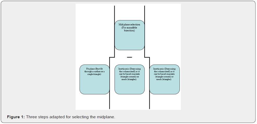
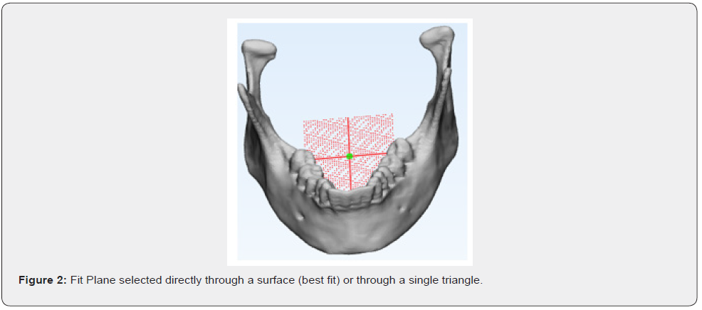
The bisection of the mandible was done by selecting the mid plane using three steps as described in Figure 1. Step one of the 3 Matic procedure is making a copy of the mandible’s mask and stowing the original away for later use as a reference. After that, you’ll need to bisect the mandible into its right and left halves to get your hands on those respective qualities. Due to the necessity of cutting the mandible in half, the cutting plane should begin at the mandible’s anterior most conspicuous point and pass through the midpoint of the line connecting the right and left mandibular foramen. An alternative sketch plane was chosen for this process. As a cellular grid with its own coordinate system relative to the object, it is used to translate 2D drawings into 3D. Figure 2 was created by selecting the Fit Plane method under the Sketch menu after the full mandible was entered as the fitting item. As a datum plane, the Fit Plane can be found at a specific location on the component.
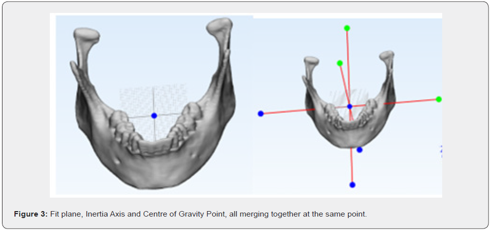
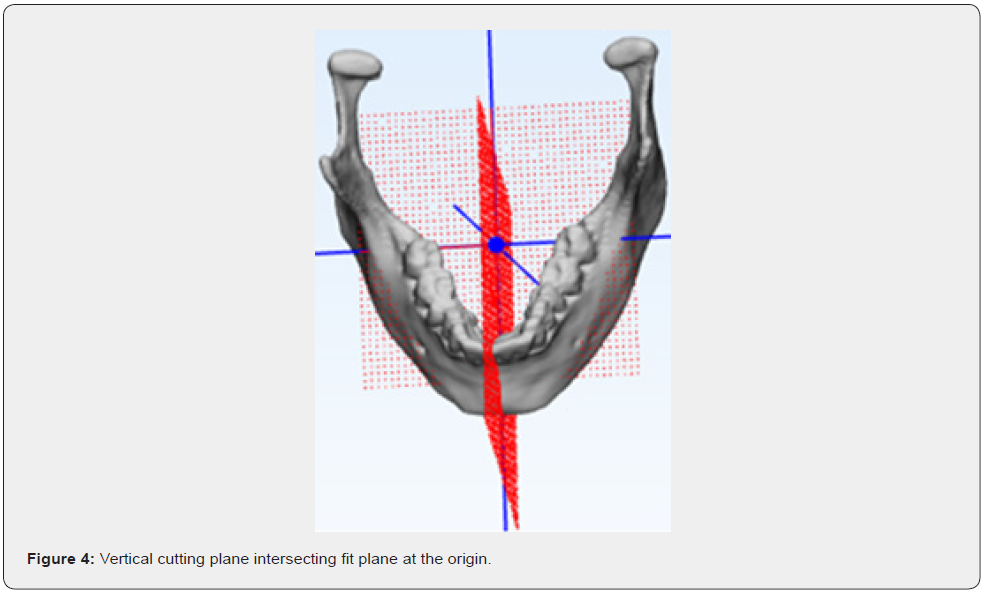
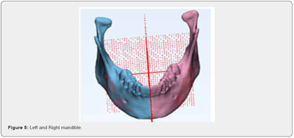
To check whether the fit plane method is accurate as per the requirement another options like the fit inertia axis and create point (centre of gravity) were used by selecting complete mandible as the fitting entity (Figure 3). All three possibilities converging at the same spot, the centre of the fit plane was identified as the best place to allow the cutting plane to pass. The cutting plane was decided upon by drawing a new sketch and then applying the technique known as “Through 2 points, perpendicular to view.” The first point was the most noticeable part of the mandibular symphysis (pogonion), and the second was the starting point for the Axis of the fit plane. In Figure 4, the mandible was divided down the middle using a vertical plane. It was decided to use the plane as the cutting entity in the design cut mode and the entire mandible as the entity to cut. After the slicing was done, it was separated into the left and right volumes, as illustrated in Figure 5.
Discussion
Reconstructing large segmental deformities and prostheses in the maxillofacial area is challenging. It’s generally accepted that covering the full defective area is best achieved by referencing the unaffected side. Nonetheless, the 3D anatomy makes it challenging in carpentry, which may lead to a less-anatomic repair and even some ugliness. Since the area’s anatomy is deformed by the growing mass, identifying the skeleton’s original shape is difficult, which greatly disrupts surgical planning. Computer-aided design has advanced to the point where a healthy side’s detailed structural picture may be mirrored and used as a reference to rebuilding the sick side. However, the human skull’s configuration is extremely complex and irregular; it is never mathematically symmetrical. As a result, finding the anatomical midway or sagittal plane is more complicated than it first appears. The truth would be off by two times if this chosen plane was skewed in any way. Since this is the case, the current research suggests a strategy of choosing the midsagittal plane to replicate the whole topic rather than just a section of it. It’s worth noting that the chin point and both condyles will end up in precisely the same places as they did before any surgery. The maintenance of the original dental occlusal pattern and the creation of a balanced facial profile are both facilitated by this principle.
Conclusion
In this research, we propose a method for VSP to determine the optimal mandibular splitting plane. Any bisection or mirroring in a maxillofacial reconstruction or prosthesis may be accomplished with this method. It has been shown that a better outcome for patients is possible. Midplanes can be selected more accurately using this method than by utilising a manual process. When selecting a midplane, it is important to consider how it will be used for anatomical reconstruction, preoperative planning, and postoperative analysis. Finally, this study’s findings shed light on the precision with which computational methods can be applied to the early diagnosis of facial asymmetry, thereby facilitating a trustworthy and valuable workflow for the evaluation and quantification of asymmetrical development and the planning of subsequent orthodontic and surgical treatments.
References
- Oral and maxillofacial surgery: challenges and changes
- Ritvik DGD, Mehta P (2004) Mandibular reconstruction in 2004: an analysis of different techniques. Curr Opin Otolaryngol Amp Head Neck Surg 12(4): 288-293.
- Saini V, Gaba S, Sharma S, Kalra P, Sharma RK (2019) Assessing the Role of Virtual Surgical Planning in Mandibular Reconstruction with Free Fibula Osteocutaneous Graft. Journal of Craniofacial Surgery 30(6): e563-e566.
- Valentini V, Agrillo A, Battisti A, Gennaro P, Calabrese L, et al. (2005) Surgical planning in reconstruction of the mandibular defect with fibula free flap: 15 patients. Journal of Craniofacial Surgery 16(4): 601-607.
- Wang WH, Deng JY, Li M, Zhu J, Xu B (2012) Preoperative three-dimensional reconstruction in vascularized fibular flap transfer. Journal of Cranio-Maxillofacial Surgery 40(7): 599-603.
- Ortún-Terrazas J, Fagan MJ, Cegoñino J, Illipronti-Filho E, Del Palomar AP (2020) Towards an early 3D-diagnosis of craniofacial asymmetry by computing the accurate midplane: A PCA-based method. Computer Methods and Programs in Biomedicine 191: 105397.
- Ko EWC, Huang CS, Lin CH, Chen YR (2022) Orthodontic Perspective for Face Asymmetry Correction. Symmetry 14(9): 1822.
- AlHadidi A, Cevidanes LH, Paniagua B, Cook R, Festy F, et al. (2012) 3D quantification of mandibular asymmetry using the SPHARM-PDM toolbox. International journal of computer assisted radiology and surgery 7(2): 265-271.
- Kwon SM, Hwang JJ, Jung YH, Cho BH, Lee KJ, et al. (2019) Similarity index for intuitive assessment of three-dimensional facial asymmetry. Scientific reports 9(1): 1-9.
- Fukuta K, Jackson IT, McEwan CN (1990) Three-dimensional imaging in craniofacial surgery: a review of the role of mirror image production. Eur J Plast Surg 13: 209-217.


