3D Computer Modeling Analysis of the Surface Area and Thread Volume of the Common Sliding Hip Screw
*Andrew Gardner1, Dominic Eggbeer2, Micheal Ryan3 and Paul Y F Lee1,4
1South Wales Orthopaedics research network, Welshbone, Cardiff, United Kingdom
2PDR Surgical Prosthetic Design, Cardiff Metropolitan University, 200 Western Avenue, Cardiff, United Kingdom
3Engaged Manufacturing, Cardiff Business School, Cardiff university, Queen’s Buildings, 5, The Parade, Cardiff, UK
4School of Engineering, Cardiff University, Queen’s Buildings, 5, The Parade, Cardiff, UK
Submission: February 12, 2017; Published: February 27, 2017
*Corresponding author: Andrew Gardner, Research fellow, South Wales Orthopaedics research network, Welshbone, Cardiff, United Kingdom, Tel:+61 432155518;Email:andrewgardner@gmail.com
How to cite this article:Gardner A, Eggbeer D, Ryan M, Lee PYF. 3D Computer Modeling Analysis of the Surface Area and Thread Volume of the Common Sliding Hip Screw. Ortho & Rheum Open Access 2017; 5(1): 555653. DOI: 10.19080/OROAJ.2017.05.555653
Abstract
Introduction: The Sliding Hip Screw (SHS) is a tried and tested method used to treat intertrochanteric hip fractures. Lag screw cut-out is a major complication of SHS fixation and accepted risk factors are often re-evaluated. We aim to demonstrate a new hypothesis of cut-out using 3D reconstructive modelling. We propose that the risk of cut-out is much greater in lag screws with a smaller thread surface area and larger thread volume.
Method: The four commonly used SHS lag screw systems (Biomet, Synthes, Stryker and Smith & Nephew) were CT scanned and the images processed and turned into 3D computer models for further analysis.
Results: There were significan differences between the surface area and thread volumes of the lag screws between manufacturers ranging from 67.0mm2 - 347.4 mm2 and 166.376mm3 - 225.687mm3 respectively.
Discussion: Assuming the consistency of bone is equal, we propose that the risk of cut-out is much greater in lag screws with a smaller surface area to thread volume ratio (SA:TV). The reamer design of lag screws is also discussed.
Conclusion: Although there are many non-modifiable risk factors that contribute to screw cut-out, selecting the right raw materials for SHS fixation will have a favorable impact on the overall risk.
Keywords: Sliding Hip Screw; Thread End; Pitch Angle; Thread Pitch; Thread Volume
Introduction
The Sliding hip screw (SHS) is the most commonly used device in the fixation of intertrochanteric hip fractures [1]. Lag screw cut out is a common post operative complication which accounts for up to 84% [2] of all fixation failures and occurs at rates between 1%-6.8% [3-5]. Lag screw depth and placement, therefore, has been quantifiable using the tip-apex distance (TAD) [6] and the ratio method [7] respectively. The TAD has been shown to be the most important predictive factor of screw cut out and in more recent studies has been stated as greater than 15mm [4]. The position of the screw in the femoral head remains an important factor and most studies agree that anterior and superior screw placement should be avoided [7-12]. Peripheral placement of the screw has also shown to increase the TAD [13].
Despite widespread agreement that the TAD is the most important factor in screw cut out it does not take into account size of the femoral head or bone density and therefore may not be an ideal concept [14]. Patient, implant and mechanical factors contributing to screw cut out have been extensively discussed in the literature and it is widely accepted that there are other factors yet to be considered. The current paper will discuss other biomechanical factors involved in screw cut out.
The SHS has a design specification (size, shape, weight, thread pattern) determined by its manufacturer. Different sizes and thread patterns suggests that varying amounts of screw would be engaged with bone at any one time and varied volumes of bone removed or compacted on reaming. We propose that the greater the surface area (SA) of the thread end (TE) of the lag screw, the better fixation and the lower the probability of screw cut-out. We aim to reinforce our hypothesis using 3-dimensional (3D) remodeling of lag screws.
Method
There are four commonly used SHS lag screw systems, Biomet, Synthes, Stryker and Smith & Nephew (SN), all of which have their own specifications. In order to quantitatively evaluate the SA of each screw type, each screw was Computer Tomography (CT) scanned with a pixel resolution of 0.346mm, slice thickness of 0.625mm and using slice increments of 0.312mm (Light Speed VCT, GE Medical, UK). The data were imported into the medical image processing software, Mimics (V16, Materialise, Belgium). This software enables CT images to be processed and turned into 3D computer models for further analysis. The ‘Thresholding’ tool was used to create a ‘mask’ of each screw based on the material density in Houns field units.
The screws showed as bright white (dense) material with a light grey halo (caused by the partial pixel effect) against a black background. A lower value of 2270 and higher value of 3071 units was chosen based upon visual analysis of how well the screw details were portrayed; values outside of this range either included a ‘halo’ effect around the screw or resulted in known details, such as the threads, from not being included in the ‘mask’. A separate ‘mask’ for each screw type was created using the ‘Region Grow’ tool and they were then labelled according to the manufacturer details.

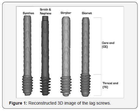
The ‘Calculate 3D from Mask’ tool was used to create a 3D model of each screw. These were aligned to be parallel to each other and in a line on screen, making it easy to compare the profiles iles (Figure 1). Once aligned, a new ‘mask’ of the screws was created using the ‘Calculate Mask from 3D’ tool. A new mask of each screw was created using the ‘Region Grow’ tool and the Core End (CE) was cropped off the mask using the ‘Crop Mask’ tool – this left just the Thread End (TE). A new 3D model of the TE sections of each screw was created to allow for analysis of the SA and thread volume (TV).
Results
Lag screw surface area

The total SA of the TE of all four lag screws is presented in Table 1. The largest SA of lag screw was manufactured by SN (1,344.071mm2± 154.811, n=4) and the smallest SA by Biomet (996.6471mm2± 154.811, n=4). The mean SA was 1185.069mm2 (± 154.811, n=4).
The SA of all four lag screws were compared against each other individually. The results of this are summarised in Table 2. The largest difference in SA of the TE was seen between SN and Biomet (347.423mm2 [34.9%] ± 113.6, n=4). The smallest difference in SA was seen between Stryker and SN (67.0mm2 [5.0%] ±113.6, n=4). The mean variation between manufacturers was 251.2mm2 (25.2%, ± 113.6, n=4).


The thread volume (TV) of the four lag screws are summarised in Table 6. The largest TV was calculated from the lag screw manufactured by Biomet (218.559mm3 ± 32.037, n=4) and smallest by SN (166.376mm3± 32.037, n=4).
Discussion
Lag screw surface area
The most common complication associated with SHS fixation is lag screw cut-out [2]. The aim of the current study was to provide evidence of other factors that might contribute to lag screw cut-out following SHS fixation. Assuming the consistency of bone is equal, we proposed that the SA of the screw in contact with bone has a significant impact on the stability of fixation and the probability of cut-out. A larger SA of screw will correspond to a greater proportion of bone engaged and reduce the load per unit area, thus will have a smaller risk of cutting-out. From the 3D reconstruction analysis, we have been able to show significant differences between the SA of the TE of the lag screws between the four different manufacturers, in some cases up to 35%. However, these figures only contribute a single factor to the overall risk of cut-out due to the large number of other factors.

It has been acknowledged in the literature that factors such as degree of osteoporosis, fracture instability, anatomic reduction, location of the screw in the femoral head and the experience of the surgeon can contribute to overall outcome of DHS fixations [7,15-17]. Of these, perhaps only some factors are modi fiable (Table 4) and therefore should be targeted in order to reduce the risk of complications associated with DHS cut out. There are large series of clinical data suggesting that the position of the lag screw in the femoral head, quantity fied by the TAD [6] and its ratio [7], is one of the major determinants of screw cut out.
In line with the proposal of our study, the SA of lag screw is a factor that can easily be controlled by the selection of the manufacture and it is easily repeatable and will not vary according to the experience of the surgeon.
Reamer design
Although the SA of lag screws is important to predict bone contact, the size and design of the reamers must also be take into account. Depending on the specific design of the reamer and its speed of reaming, varying volumes of bone will be removed or compacted into the femoral head, potentially altering its density and bio-mechanical characteristics. The sharpness of the reamers as well as the surgical reaming technique would also influence the quality of the hole, these factors vary in each individual case (Table 5) summaries.


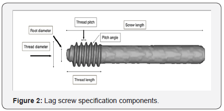
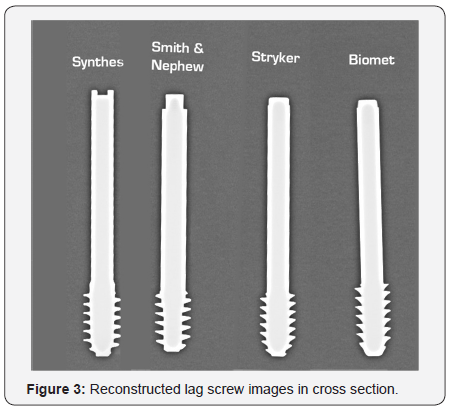
Figure 2 the mechanical factors that can influence the fixation of the lag screw. The design of the reamer and corresponding lag screw thread design is defined by a number of different components: pitch angle, thread pitch, root diameter, thread diameter and thread length (Figure 2). When comparing the lag screw specifications between manufactures [18-20], the thread length and thread pitch was seen to be fairly consistent. There was, however, some variability in pitch angle (PA). Considering only biomechanical factors in good quality bone, when thread pitch remains constant, it is the PA that influences the volume of bone removed (thread volume). As the PA increases so does the area, in cross-section (Figure 3), corresponding to a greater thread volume (TV).

For example, the S&N lag screw design had the smallest PA and thus will correlate with a smaller volume within its thread (Table 5). Conversely, Biomet, S&N and Stryker screws all have a larger PA that increases the SA and TV as well as providing better tensional strength to the screw. This would also reduce the chance of screw breakage during removal.
Surface area to thread volume ratio (SA:TV)
In theory, a larger pitch size will capture a large amount of bone which should provide a better pull out strength. Experimentally, it has been shown that a greater pitch angle in pedicle screws provides an increase in pull out force [21]. As mentioned above, a greater pitch angle corresponds to a larger volume of bone being removed on reaming and therefore, a greater pull out strength. Quantifying the strength of screw engagement with regard to the above factors is beyond the scope of this paper but is something to consider as an additional variable to overall outcome.
The lag screw on the SHS, however, is not designed to prevent pull out but the mode of failure is usually superior lateral cut out. Thus, the SA of the screw would have a more practical value as compared to the pitch size in this context as the SA would represent the area of loading, therefore increased SA contact between screw and bone will reduce the forces transmitted per unit area. In addition to this, when considering the cohort of patients in which the SHS is used, removing large volumes of bone in elderly osteoporotic patients would further de-stabilise the fixation. Therefore, a screw that that removes the least amount of bone would be more favourable. Taking into account the significant differences in SA between screw manufacturers and the importance of keeping good quality bone insitu, we propose that a lag screw with a greater Surface Area (SA) to Thread Volume (TV) ratio (SA:TV) would provide a more stable fixation and reduce the probability of lag screw cut out. From our analysis, the company that manufactured a lag screw with the largest SA and smallest volume of bone removed after reaming, i.e large SA:TV ratio, was S&N (SA:TV = 8.079). In contrast, the lag screws with a small SA and large volume of removed bone, i.e small SA:TV ratio, was manufactured by synthesis (SA: TV= 4.976), Biomet (SA: TV= 4.560) and Stryker (SA:TV= 5.679) (Table 4).
There has been many different factors documented in the literatures relating to SHS lag screw cut out and its mode of failure, some of the risk factors are well established [11,18]. However there has not been any report looking at the characteristics and SA of the lag screws between manufacturers. Although we cannot adjust for the experience of the surgeon, fracture pattern and quality of bone, we can be selective in the implant we use, resulting in a more favourable risk calculation for screw cut-out. We believe a SA:TV ratio quantifies an established complication (cut-out) of DHS fixation and specifically addresses the biomechanical factors involved.
Limitations
The limitation of this study is that it is based on a computer model of the lag screws. Further bio-mechanical and clinical outcome studies need to be conducted to look at cut-out rates against SA of the different lag screws.
Conclusion and Recommendation
The size, pitch and thread of lag screws are different between manufacturers. These components will influence the contact SA between the implant bone interface, affect the load per unit area to the surrounding bone, de fine the volume of bone removed on reaming and ultimately influence cut out. It is, therefore, important for surgeons to understand the difference between manufacturer specifications as well as the cost of the implant.
References
- Liu M, Yang Z, Pei F, Huang F, Chen S, et al. (2010) A meta-analysis of the Gamma nail and dynamic hip screw in treating peritrochanteric fractures. Int Orthop 34(3): 323-328.
- Lorich DG, Geller DS, Nielson JH (2004) Osteoporotic pertrochanteric hip fractures: management and current controversies. Instr Course Lect 53: 441-454.
- Andruszkow H, Frink M, Fromke C, Matityahu A, Zeckey C, et al. (2012) Tip apex distance, hip screw placement, and neck shaft angle as potential risk factors for cut-out failure of hip screws after surgical treatment of intertrochanteric fractures. Int Orthop 36(11): 2347- 2354.
- Hsueh KK, Fang CK, Chen CM, Su YP, Wu HF, et al. (2010) Risk Factors in Cutout of Sliding Hip Screw in Intertrochanteric Fractures: An Evaluation of 937 Patients. Int Orthop 34(8): 1273-1276.
- Windolf M, Braunstein V, Dutoit C, Schwinger K (2008) Is a helical shaped implant a superior alternative to the Dynamic Hip Screw for unstable femoral neck fractures? A biomechanical investigationClinical Biomechanics 24(1): 59 - 64.
- Baumgaertner MR, Curtin SL, Lindskog DM, Keggi JM (1995) The value of the tip-apex distance in predicting failure of fixation of peritrochanteric fractures of the hip. J Bone Joint Surg Am 77:1058- 1064.
- Parker MJ (1992) Cutting-out of the dynamic hip screw related to its position. British editorial Society of Bone and Joint surgery 74(4): 625.
- Baumgaertner MR, Solberg BD (1997) Awareness of tip-apex distance reduces failure of fixation of trochanteric fractures of the hip. J Bone Joint Surg Br79(6): 969- 971.
- Davis TRC, Sher JL, Horsman A, Simpson M, Porter BB, et al. (1990) Intertrochanteric femoral fractures.Mechanical failure after internal fixation. J Bone Joint Surg 72(1): 26-31.
- Kyle RF, Caanela ME, Russell TA, Swiontkowski MF, Winquist RA, et al. (1995) Fractures of the proximal part of the femur. Insta Course Lect 44: 227-253.
- Lindskog DM, Baumgaertner MR (2004) Unstable intertrochanteric hip fractures in the elderly. J Am Acad Orthop Surg 12(12): 179-190.
- Pervez H, Parker MJ, Vowler S (2004) Prediction of fixation after sliding hip screw fixation. Injury 35(10): 994-998.
- Guven M, Yavuz U, Kadioglu B, Akman B, Kilncoglu V, et al. (2010)Importance of screw position in intertrochanteric femoral fractures treated by dynamic hip screw. Orthopaedics & Traumatology: Surgery research 96(1): 21-27.
- Goffin JM, Jenkins PJ, Ramaesh R, Pankaj P, Simpson AH (2013) What Is the Relevance of the Tip-Apex Distance as a Predictor of Lag Screw Cut- Out?. PLoS ONE 8(8): e71195.
- Jahng JS, Yoo JH, Sohn JS (1997) The relationship between the fractures of the hip and the bone mineral densityover fifty years. J Korean Orthop Surg 32(10): 46-52.
- Kim WY, Han CH, Park JI, Kim JY (2001) Failure of intertrochanteric fracture fixation with a dynamic hip screw in relation to pre-operative fracture stability and osteoporosis. Int Orthop 25(6): 360-362.
- Oger P, Katz V, Lecorre N, Beaufils P (2008) Fracture of the greater trochanter treated by dynamic hip screw plate: measure of impaction according to fracture type. Rev Chir Orthop Reparatrice Appar Mot 84(6): 539-545.
- Biomet Trauma (2015) TK2 Compression Hip Screw, screw system
- Synthes (2015) DHS/DCS Dynamic hip and condylar screw systems, Surgical technique.
- FSmith and Nephew (2015) Compression hip screw, Surgical technique.
- Chatzistergos PE, Magnissalis EA, Kourkoulis SK (2010) A parametric


