




 JOJMS Home



Abstract
The balanced cementing is one of the most important measures to ensure the well cementing quality. Borehole fluids expand with the formation heating and compress with the fluid column pressure, which causes variations of the borehole fluids density. Inadequate choose of injected fluids density can easily cause the pressure unstable because of the narrow safety pressure window, big temperature difference & pressure difference of deep wells and high temperature & high-pressure wells. By the self-developed HTHP fluids density variation gauge, the author has measured the density variation curves of water, spacer fluids, cement slurry and mineral oil affected by temperature and pressure, and selected the suitable density model for the temperature & pressure variation of cement slurry. This paper mainly introduces the operating mechanism and experimental phenomena of the self-developed gauge, and then calculates the static equivalent density curves of water-base and oil-base mud with different injecting density under the condition of different down-hole geothermal gradients, providing references for the density design of drilling and cementing fluids of deep wells and high temperature & high-pressure wells.
Keywords: Temperature; Pressure; Borehole fluids; Density variation; Cementing design; Drillbench software
Abbreviations: RBF: Radial Basis Function; MLP: Multilayer Perceptron; LSSVM: Least Square Support Vector Machine; GA: Genetic Algorithm; ICA: Competitive Algorithm; PSO: Particle Swarm Optimization; PVT: Pressure-Volume-Temperature; ESD: Equivalent Static Density; HTHP: High-Temperature and High-Pressure
Introduction
Many difficulties are encountered during drilling and well completion in high-temperature and high-pressure (HTHP) environments. One such challenge is that the density of the drilling fluid and cement slurry is not constant but changes with temperature and pressure [1]. Predicting the true density of a downhole working fluid has become a key issue in the design and construction of drilling and cementing to prevent blowout and leakage in HTHP wells within a narrow pressure window [2].
Due to technical difficulties and high economic and time costs in measuring the actual densities of drilling and completion fluids under high temperatures and high pressures, integrated algorithms and models for drilling fluid prediction have been proposed, including linear empirical analytical, correlation and intelligent approaches. In particular, Adamson et al. reported the effect of high temperature and high pressure on the drilling fluid density as the source of the wellbore instability in HTHP wells [3]. Kutasov proposed a model with empirically regression coefficients for determining the density of downhole drilling fluids [4] at the University of Texas calculated the effect of the drilling fluid density on the downhole pressure based on a component model for the drilling fluid density [5] proposed a density model for pure and mixed-salt brines [6] studied the effects of temperature and pressure on the density of water- and diesel-based drilling fluids [7]. used a materials balance approach to develop a composition prediction model for the density of water- and diesel-based drilling fluids, i.e., a so-called “composite model” [8]. However, different components of the drilling fluid (water, oil and the solid phase) must be separately tested to determine the respective rules before the model can be applied. Application of this model is thereby restricted. Babu at the Indian Oil Corporation, Limited used an empirical model for the drilling fluid density to determine the effect of changes in the drilling fluid density on the static pressure but produced an evidently problematic formula [9]. Wang at the SINOPEC Petroleum Exploration and Production Research Institute developed an empirical model for the drilling fluid density [10]. This model does not distinguish between the effects of oil and water on the density and was not validated by experimental data. Intelligent models have been proposed in recent years, such as the radial basis function (RBF) [11-13], multilayer perceptron (MLP) [14,15] and least square support vector machine (LSSVM) based on the original model of Suykens [16,17], genetic algorithm (GA) [18], imperialist competitive algorithm (ICA) [19], particle swarm optimization (PSO) [20] and composite models thereof. A variety of density models have been used for oil- and water-based drilling fluid systems worldwide, but a cement slurry model has not been developed. Therefore, the objective of this study was to design an instrument for measuring the drilling fluid density in a well at a specific temperature and pressure and to use the obtained data to develop an appropriate density model for a drilling fluid and cement slurry.
Experimental Instruments, Principles and Methods
Experimental instruments
Figure 1 shows the instrument designed to measure changes in the density of a bottomhole fluid in HTHP environments. The three main components of the instrument are a tank, a temperature control system and a pressure-volume-temperature (PVT) pressure control system.
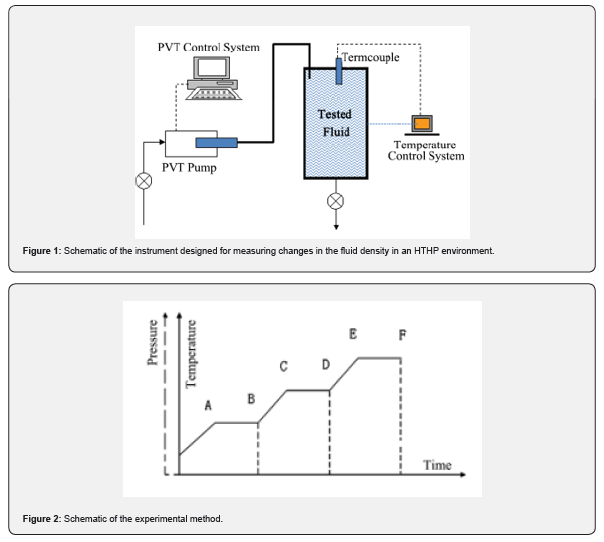
The tank is used to hold the fluid sample to be tested and provide a closed HTHP-resistant environment.
The main components of the temperature control system are a 7040 thermostat and a temperature sensor. The experimental scheme consists of using different heating durations and target temperatures to simulate the downhole environmental temperature.
The main components of the PVT pressure control system are a PVT pump and a PVT data acquisition system. The PVT pump accurately controls the tank pressure through the displacement of a piston, and the PVT data acquisition system accurately measures the volume change of the fluid that drives the piston under a given pressure.
Experimental principle
Changes in the volume of the test fluid in the tank with the temperature and pressure cause the PVT piston to move. The computer control system calculates the volume of the outflow/inflow of the tank through a displacement sensor. The corresponding change in the weight of the fluid for a fixed tank volume (250ml) was used to calculate the density of the fluid at this temperature and pressure as given below.
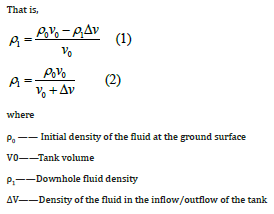
where
ρ0 —— Initial density of the fluid at the ground surface
V0——Tank volume
ρ1——Downhole fluid density
∆V——Density of the fluid in the inflow/outflow of the tank
Experimental method
i. The test fluid is fed into the tank. If the test fluid is a cement slurry or weighted mud, a small quantity of water should be added to the top of the tank.
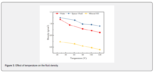
ii. The temperature control system is used to set the temperature at different test points following the same procedure used to test the compressive strength of a cement slurry, as shown in Figure 2. The temperature at each test point should be maintained for more than 30 minutes (e.g., the length of time between A and B should be greater than 30 minutes) to ensure that all the fluid in the tank is heated to the same temperature. Tests are performed by increasing the fluid temperature from low to high. Figure 2 Schematic of the experimental method
iii. The test pressures at different test temperature points are set by the pressure control system.
iv. At the end point of each constant-temperature test segment (B, D and F in Figure 2), the inflow and outflow volumes of the tank are recorded.
v. The density at each end point is calculated according to Equation (2).
Analysis of the Effects of Temperature and Pressure on the Fluid Density
Effect of temperature on the fluid density
Changes in the densities of the spacer fluid, fresh water and mineral oil were determined at different temperatures and a fixed pressure of 6.89MPa. The test results presented in Figure 3 show that temperature affected the densities of the three fluids to different extents. Increasing the temperature from 20°C to 120°C resulted in a decrease in the densities of the spacer fluid, fresh water and mineral oil of 5.58%, 7.3% and 7.76%, respectively.
Effect of pressure on the fluid density
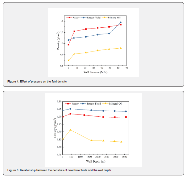
Changes in the densities of the spacer fluid, fresh water and mineral oil were determined at different pressures and a fixed temperature of 30°C. The initial densities of the spacer fluid and the mineral oil were 1.04 g/cm3 and 0.85 g/cm3, respectively. The test results presented in Figure 4 indicate that the pressure affected the density of the three fluids to different extents. Increasing the pressure from atmospheric to 63MPa resulted in a decrease in the densities of spacer fluid, fresh water and mineral oil of 13%, 17.6% and 7.7%, respectively.
Effect of temperature and pressure on the fluid density
Tests were performed on the spacer fluid, fresh water and mineral oil using the procedure described in Table 9.12 of the Procedure for Testing Well Cements (GB/T 19139-2003) with a geothermal gradient of 3.5°C/100 m [21] and the test conditions shown in Table 1. The test results are shown in Table 1 and Figure 5.
The test results showed that as the well depth increased from 0 m to 2,944m, the densities of the spacer fluid, fresh water and mineral oil decreased by 0.288%, 0.30% and 1.4%, respectively, under the combined effect of temperature and pressure.
Selection of a cement grout density model
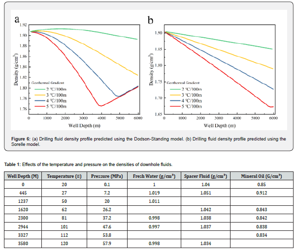
Drillbench software has been used to establish a PVT model, a heat-transfer model and a flow model to describe the variation in the drilling fluid density with the temperature and pressure. Three density models have been established for water-based fluids: the Dodson-Standing, Kemp-Thomas and Sorelle models. These models produce quite different predictions. Figure 6 show the density of a water-based drilling fluid (with a density of 1.9 g/cm3 at the surface temperature of 20°C) calculated using the Dodson-Standing and Sorelle models, respectively.
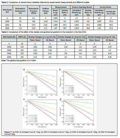
Table 2 is a comparison of the experimental results and the model predictions, showing that the Dodson-Standing model is more suitable than the Sorelle model for describing a cement slurry under downhole conditions.
Effect of the geothermal gradient and initial inflow fluid density on the equivalent static density (ESD)
Drillbench software has been used to establish four density models for oil-based fluids: the Standing, Glass, Sorelle and Table models. The Sorelle (oil) model is recommended among these models.
Figure 7 & 8 show the results of using the Sorelle (oil) and Dodson-Standing models to calculate the ESD of fluids with different initial inflow fluid densities. Figure 7 & 8 show that at the lower the drilling fluid density and the higher the geothermal gradient are, the larger the impact of the temperature and pressure on the density is. Table 3 shows that changes in temperature and pressure produce larger density changes in oil-based drilling fluids than in water-based drilling fluids.
Test results and discussion
i. The initial inflow fluid density can be selected from Figures 8 to 15 based on the formation equivalent density and the types of drilling and completion fluids.
ii. To calculate the stable pressure for HTHP cementing, the effective residual pressure should be calculated using the actual density in the well considering temperature and pressure effects.
Conclusion
i. A set of methods for evaluating changes in the fluid density in HTHP environments has been established, and a test instrument with high operability has been designed.
ii. Temperature and pressure have quite different effects on water-based fluids than oil-based fluids. For both water- and oil-based drilling fluids, the actual fluid density in deep wells decreases with increasing well depth, and the fluid density in the upper well segment is slightly higher at low geothermal gradients than at high geothermal gradients.
iii. The lower the drilling fluid density and the higher the geothermal gradient are, the larger the impact of the temperature and pressure on the density is. Changes in the temperature and pressure produce larger density changes in oil-based drilling fluids than in water-based drilling fluids.
iv. As the well depth increases from 0 m to 5,000 m at 250 °C, the densities of water- and oil-based muds decrease by 5.58% and 6.4%, respectively.
v. The Dodson-Standing model is suitable for evaluating the effect of temperature and pressure on the density of a cement slurry.
vi. The downhole ESD map calculated by Drillbench software can be used to select the initial inflow fluid density that stabilizes the formation pressure.
References
- Zhao JC, Westbrook JH (2003) Ultrahigh-temperature materials for jet engines MRS Bull 28: 622-627.
- Tsakiropoulos P (2022) Alloys for application at ultra-high temperatures: Nb-silicide in situ composites: Challenges, breakthroughs and opportunities. Progress in Materials Science 123: 100714.
- Graham SJ, Gallagher E, Baxter GJ, Azakli Y, Weeks J, et al. (2024) Powder production, FAST processing and properties of a Nb-silicide based alloy for high temperature aerospace applications. Journal of Materials Research and Technology 28: 3217-3224.
- Tsakiropoulos P (2018) On the Nb silicide-based alloys: Part I The bcc Nb solid solution. Journal of Alloys and Compounds 708: 961-971.
- Tsakiropoulos P (2017) On the Nb silicide-based alloys: Journal of Alloys and Compounds. Part II Journal of Alloys and Compounds 748: 569-576.
- Bewlay BP, Jackson MR, Subramanian PR (2003) A review of very-high-temperature Nb-silicide-based composites. Metall Mater Trans A 34: 2043-2052.
- Ma R, Guo X (2021) Influence of molybdenum contents on the microstructure, mechanical properties and oxidation behavior of multi-elemental Nb–Si based ultrahigh temperature alloys. Intermetallics 129: 107053.
- Qiao Y, Guo X, Zeng Y (2017) Study of the effects of Zr addition on the microstructure and properties of Nb-Ti-Si based ultrahigh temperature alloys. Intermetallics 88: 19-27.
- Kang YW, Qu SY, Song JX, Huang Q, YF Han (2012) Microstructure and mechanical properties of Nb–Ti–Si–Al–Hf–xCr–yV multi-element in situ composite. Mater Sci Eng A 534: 323-328.
- Grammenos I, Tsakiropoulos P (2010) Study of the role of Al, Cr and Ti additions in the microstructure of Nb–18Si–5Hf base alloys. Intermetallics 18(2): 242-253.
- Zelenitsas K, Tsakiropoulos P (2005) Study of the role of Al and Cr additions in the microstructure of Nb–Ti–Si in situ Intermetallics 13(10): 1079-1095.
- Li Zh, Luo L, Wang B, Su B, Luo L, et al. (2023) Cooperative effects of Mo and B additions on the microstructure and mechanical properties of multi-elemental Nb-Si-Ti based alloys. Part A Materials Characterization 206: 113421.
- Solntsev VP, Skorokhod VV, Frolov GA (2016) Development of a heat-resistant alloy based on niobium for thermal protection of rocket and space technology products. Bulletin of Engine Building 2: 198-206.
- Senkov ON, Senkova SV, Miracle DB, Woodward C (2013) Mechanical properties of low-density, refractory multi-principal element alloys of the Cr-Nb-Ti-V-Zr system. Mater Sci & Engineering: A 565: 51-62.
- Brodnikovskyi MP, Kuznetsova TL, Rokytska OA, Krapivka MO (2018) Features of the formation of the cast structure of multicomponent niobium alloys of the Nb-Ti-Al system doped with Cr, Zr, Mo and Si. Physical metallurgy and metal processing 3: 56-61.
- Kimura Y, Yamaoka H, Sekido N, Mishima Y (2005) Processing, Microstructure, and Mechanical Properties of (Nb)/Nb5Si3 Two-Phase Alloys. Metallurgical and materials transactions A 36: 483-488.
- Drawin S, Monchoux JP, Raviart JL, Couret A (2011) Microstructural properties of Nb-Si based alloys manufactured by powder metallurgy. Advanced Materials Research 278: 533-538.
- Nakajima H (1997) The Discovery and Acceptance of the Kirkendall Effect: The Result of a Short Research Career. JOM 49: 15-19.
- Fischmeister HF, Arén B, Easterling KE (2014) Deformation and densification of porous preforms in hot forging. Powder Metallurgy 14(27): 144-163.
- Baglyuk GA, Tolochin AI, Tolochina AV, Yakovenko RV, Gripachevckii AN, et al. (2016) Effect of Process Conditions on the Structure and Properties of the Hot-Forged Fe3Al Intermetallic Alloy. Powder Metall Met Ceram 55(5): 297-305.