


An Analytical Model for Axial Force Transfer and the Maximum Compression Point of Work Strings in Extend Reach Drilling
Boyun Guo and Rashid Shaibu*
Department of Petroleum Engineering, University of Louisiana, Lafayette, USA
Submission:November 15, 2020;Published:December 18, 2020
*Corresponding author: Rashid Shaibu, Department of Petroleum Engineering, University of Louisiana, Lafayette, USA
How to cite this article: Boyun G, Rashid S. An Analytical Model for Axial Force Transfer and the Maximum Compression Point of Work Strings in Extend Reach Drilling. Insights Min Sci technol.2020; 2(4): 555592. DOI: 10.19080/IMST.2020.02.555592
Abstract
Complex work string dynamics are often observed when one is investigating the limit of Extended Reach Drilling (ERD), yet the underlying physical causes of anomalous problems are often not fully understood and is thus a topic of ongoing research interest. Theoretical models capturing tubular dynamics have been previously proposed to analyze force transfer in work strings, yet there is significant confusion regarding these models because their published versions are not entirely consistent and, in many cases, do not meet engineering requirement. Further confusion is introduced through variations in pin-pointing locations where axial compression in the work strings should be checked for mechanical integrity. A simple and yet rigorous mathematical model is essential for adequate prediction of axial compression profiles in work strings for ERD. This article presents a simplified tubular mechanics model for describing axial force transfer under ERD conditions. We discuss the model in finding the point of peak compression in casing strings. This point is predicted to be in the arc section near the heel of a horizontal wellbore, under borehole drilling, and casing running conditions. The exact location of the peak axial compression changes with pipe-wall friction coefficient. For the friction coefficient in the range of 0.15 to 0.35, this point occurs in the range of inclination angle between 70.7o and 81.5o, averaging 76.1o. The model can also be used for other purposes, including prediction of depth limit, bottom hole assembly (BHA) design, and locking up analysis of coiled tubing (CT) strings.
Keywords: Extended-reach-wells; Casing design, Work strings; Drilling; Stability
Introduction
Extended reach wells (ERW) are horizontal wells used for reaching oil and gas resources located laterally and far from well location. ERW has become a common practice over the last two decades for improving field economics. Extended Reach Drilling (ERD) is a technique to drill directional/horizontal wells beyond the routine capabilities of drilling rigs and tools. ERD was initiated in 1980’s and rapidly evolved during the 1990’s [1-4]. Naegel et al. [5] reported an ERD well with a 20,341.2 ft horizontal departure at 5,577 ft true vertical depth (TVD). ERD continued in the past two decades with new record updated every a few years [6-11]. Armstrong and Evans [12] reported planning and execution of an offshore ERD well of a total measured depth (MD) of 37,165 ft with TVD of 6,938 ft, and horizontal displacement (HD) of 33,682 ft. Tskhadaya et al. [13] presented a design of ERD for an Arctic well depth of 49,212.6 ft and horizontal borehole depth of 4,921.3 ft.
Special technical issues in ERD include rig requirement, borehole stability, cuttings transport, data acquisition, and drill string design. In the particular topic of our ongoing research interest, i.e., tubular mechanics of work strings (drill string, coiled tubing string, and casing string), Nixon et al. [14] presented techniques to solve the problems associated with excessive torque during ERD. Hill et al. [15] discussed designing and qualifying drill strings for ERD while Mason and Judzis [16] discussed the limit of ERD, and Suggett and Smith [17] addressed the issue of ERD limit for rig capacity. Bell et al. [18] reported an application of significant increases in the lateral reach of a number of ERW’s. Samuel [19] presented a new well-path design that can extend the reach of ERW through reducing torque and drag using curvature and torsion discontinuities. Agbaji [20] presented an algorithm that would set forth design for drilling programs suitable to ERD. Vestavik et al. [21] presented a potential application of Reelwell Drilling Method (RDM) to widen the envelope of ERD through reductions of torque and drag and Equivalent Circulating Density (ECD) gradient, and optimization of hydraulic weight on bit. Newman et al. [22] explained that for ERD with coiled tubing (CT) where a limitation on the horizontal displacement occurs due to frictional forces, the friction can cause helical buckling and lead to lockup of the CT strings, thus limiting reach. Gupta et al. [23] discussed several key challenges in ERD, including high torque and drag due to high friction forces.
Theoretical models capturing tubular dynamics have been previously proposed to analyze force transfer in the work strings used in ERD, yet there is significant confusion regarding these models because they are are not entirely consistent and, are hard to use due to model complexity. Also, no model has been found to have the capacity of pin-pointing the locations where the axial compression in work strings should be checked for mechanical integrity. A simple and rigorous analytical solution in closed form is presented in this work for adequate prediction of axial compression profiles in the work strings for ERD. We discuss the model in finding the point of peak compression in casing strings. This point is predicted to occur in the arc section, near the heel of a horizontal wellbore, under borehole drilling and casing running conditions. The model can also be used for other purposes, including prediction of depth limit, BHA design, and lockup condition analysis of CT strings.
Mathematical Model
Figure 1 illustrates a simplified configuration of a work string (drill string, casing string, or coiled tubing string) used in horizontal well construction engineering. Two-dimensional well trajectory of build-and-hold type is considered. The string is assumed to contact the lower side of borehole due to gravity in the curve and slant/horizontal sections without buckling. Owing to its large length-to-diameter ratio, the string is considered to be ropelike without stiffness. It is subjected to axial tension/compression but not bending moment.

The axial compression force in the vertical section of string increases with depth due to gravity. Its value at the kick-of-point (KOP) is expressed as

Where F0 is the axial compressive force in the string at KOP, wv is the weight per length of the string in the vertical section, V is the length of vertical string section, and T is the tension at the surface (hook load). In the down-ward motion, the axial compression force in the horizontal section increases with the distance from the end of string (toe of horizontal well) due to friction. The axial compression force at the heel reaches to

Where 2fθ is the axial compressive force in the string at the heel of horizontal well, μ is the friction coefficient between the string and borehole wall, wh is the weight per length of the string in the slant/horizontal section, H is the length of string in the slant/horizontal section, θ2 is the inclination angle at the heel point, WB is the force acting back by the borehole bottom (weight on bit in drilling condition), Ah is the cross-sectional area of string in the horizontal section, and pf is the fluid pressure in the bottom hole. If the slant section is truly horizontal (θ2 = π/2), Eq. (2) degenerates to

where Fπ /2 is the axial compressive force at the heel.
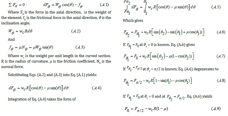
Because the axial compression force in the string is a continuous function of length, its value is expected to reach a maximum between F0 and Fπ /2 in the curved section. The axial compression force in the curve section is expressed as (see Appendix A for derivation):
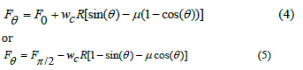
Where wc is the weight per length in the curved section, and R is the radius of curvature.
Equation (5) is plotted in Figure 2 for Fπ/2 = 20,000 lb, wc = 17 lb/ft, and R = 1,000 ft for friction coefficient values ranging from 0.15 to 0.40. It indicates that a maximum value of axial compression exists near the heel, depending on friction coefficient.

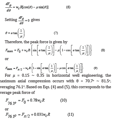
The maximum axial compression force occurs at a point where the function is stationary. The derivative of this function is
Model Applications
This mathematical model can be used in casing design, drill string design, and coiled tubing stability analysis in horizontal well engineering. Two examples are illustrated in this section.
Casing Design. Casing strings for horizontal wells are designed considering multiple stress components that cause:
a) Burst failure due to net bust pressure
b) Collapse failure due to net collapse pressure
c) Tensile/compressive failure due to axial forces (gravity, friction, and bending)
The axial compression force can reduce the casing’s burst resistance performance. Suppose a 5½” J-55, 17 lb/ft, production casing is selected to run in the curve section of the borehole shown in Figure 3. The mud weight is 12.5ppg and friction coefficient is 0.30. It is required to check the reduced burst pressure resistance of the casing due to axial compression.
The API burst pressure resistance of the casing is [24]:
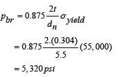
Where t is the thickness, dn is the nominal pipe diameter, and σyield is the yield stress
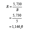
Radius of curvature is [24]:
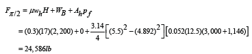
Axial compression at heel is
A complete profile of axial force was calculated with the mathematical model and is shown in Figure 4. It shows a maximum axial compression near, but not at the heel.


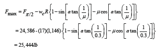
The maximum axial compression is
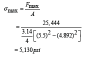
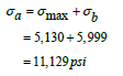
The maximum axial stress due to weight and friction is
Bending stress is
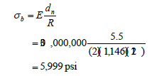
Where σb is the bending stress, and E is the Young’s modulus of elasticity. The total axial compression is
API tangential stress factor for burst is [24]:
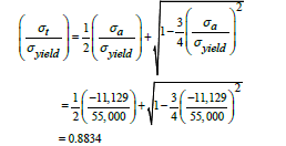
Where σt is the tangential stress.
Reduced burst pressure resistance of the casing is [24]:
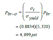
which means that the axial compression will reduce burst pressure resistance of the casing from 5,320 psi to 4,699 psi, or by 12%.
Drill String Design. Drill strings for horizontal wells consists of drill collar design, considering friction forces in the curved and horizontal sections, under drilling conditions (down-ward motion), and drill pipe design considering over-pull under, tripping-out conditions (upward motion).
Consider the situation shown in Figure 5. Design parameters are given in Table 1. Equation (2) gives


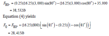
The required drill collar weight is (1.15)(28,415) or 32,677 lb. Based on the unit weight of 92 lb/ft of the drill collar, the required drill collar length is (32,677)/(92) or 356 ft.
For drill pipe design, the curved linear length of the arc section is (800)(80)/(57.3) or 1,117 ft. The weight of the lower drill pipe is (16.25)(3,000+1,117) or 66,900 lb. Based on the tensile capacity of Grade G steel pipe, 436,000 lb, the maximum pull on the Grade G drill pipe with design factor is (436,000)/(1.15) or 379,130 lb. The maximum permissible weight of Grade G pipe string with over pull of 100,000 lb is
379,130 – 66,900 – 32,677 – 100,000 = 179,553 lb The maximum permissible length of this pipe string is (179,553)/(19.5) or 9,208 ft, which is greater than the needed length of 10,000 – 3,000 – 1,117 – 356 = 5,527 ft,
Conclusion
An analytical model for axial force transfer and the maximum compression point in work strings for ERD was developed in this investigation. The following conclusions are drawn.
a) The maximum axial compression point is in the arc section near the heel of a horizontal well when the work string is in down-ward motion. The exact location of the maximum axial compression changes with casing-wall friction coefficient. For μ = 0.15 ~ 0.35 in horizontal well engineering, the maximum axial compression occurs with θ = 70.7o ~ 81.5o, averaging 76.1o.
b) When applied to casing design, the maximum compression point model can be easily used to evaluate the reduction of the casing’s burst resistance performance. Results show that the casing’s burst resistance performance can be significantly reduced due to axial compression (12% in the illustrative example).
c) When applied to drill string design, the axial force transfer model can be easily utilized to determine the required drill collar weight and length, which is further used for selecting drill pipe string.
d) Future studies should validate the mathematical model and investigate the applicability of the model to CT stability analysis and predict the depth limit of ERD.
Nomenclature
A Cross sectional area
Ah Cross-sectional area of string in the horizontal section.
BHA Bottom hole assembly
CT Coiled tubing
dn Nominal diameter
E Young’s modulus of elasticity
ECD Equivalent circulating density
ERD Extended reach drilling
ERW Extended reach wells
F0 Axial compressive force in string at KOP
Fmax Peak force
fθ2 Axial compressive force at the heel.
fθ Frictional force in the axial direction
H Length of string in the slant/horizontal section.
HD Horizontal displacement
KOP Kick of point
Nθ Normal force
T Tension at the surface
t Thickness
TVD Total vertical depth
V Length of vertical string section.
WB Force acting back by the borehole bottom (weight on bit in drilling condition).
wh Weight per length of string in the slant/horizontal section.
wc Weight per length of string in the curved section
wv Weight per length of string in the vertical section.
R Radius of curvature
pbr-σ Reduced burst pressupbr Burst pressure resistance
pf Fluid pressure in the bottom hole.
ppg Pound per gallon
σa Total axial compression
σb Bending stress
σmax Maximum axial stress
σt Tangential stress
θ Inclination angle
θ2 Inclination angle at the heel point
μ Friction coefficient
Acknowledgment
This research was supported by the U.S. - Israel Center of Excellence in Energy, Engineering and Water Technology through the project “Safe, sustainable, and resilient development of offshore reservoirs and natural gas upgrading through innovative science and technology: Gulf of Mexico – Mediterranean.”
Appendix A: Derivation of Axial Force Transfer Model for Work Strings in the Arc Section of Horizontal Well Trajectory
A method for predicting the transfer of axial load in the work string can be derived for rope-like strings (no stiffness). Consider an element of the curve section of string with length dl =Rdθ as shown in Figure A1.

References
- Mueller MD, Quintana JM, Bunyak MJ (1991) Extended-Reach Drilling from Platform Irene. Society of Petroleum Engineers.
- Eck Olsen J, Sletten H, Reynolds JT, Samuell JG (1993) North Sea Advances in Extended Reach Drilling. Society of Petroleum Engineers.
- Ryan G, Reynolds J, Raitt F (1995) Advances in Extended Reach Drilling - An Eye to 10km Stepout. Society of Petroleum Engineers.
- Dolan SP, Crabtree RC, Drury RF, Gogan R, Hattersley G, et al. (1998) Planning, Execution and Lessons Learned from the GWA13 Extended Reach Drilling Well - Goodwyn Gas/Condensate Field, NWS, Australia. Society of Petroleum Engineers.
- Naegel M, Pradie E, Beffa K, Ricaud J, Delahaye T (1998) Extended Reach Drilling at the Uttermost Part of the Earth. Society of Petroleum Engineers.
- Elsborg CC, Power AK, Schuberth PC (2005) Hibernia Record Well Breaks Extended Reach Drilling and Completion Envelope. Society of Petroleum Engineers.
- McDermott JR, Viktorin RA, Schamp JH, Barrera MW, Fleming JM, et al. (2005) Extended Reach Drilling (ERD) Technology Enables Economical Development of Remote Offshore Field in Russia. Society of Petroleum Engineers.
- Algu D, Landgrave S, Esquinance B, Volokitin Y, Derise B (2005) Extended Reach Drilling in the GOM - Ram Powell Case Study. Society of Petroleum Engineers.
- Woodfine M, Ottesen S, Trend S, Bolivar N (2011) Hibernia Well Overcomes Challenges to Further Extend Worldwide Extended Reach Drilling (ERD) Envelope. Society of Petroleum Engineers.
- Walker MW (2008) Extended-Reach Drilling - Offshore California: An Operator’s Experience with Drilling a Record Extended-Reach Well. Society of Petroleum Engineers.
- Walker MW, Veselka AJ, Harris SA (2009) Increasing Sakhalin Extended Reach Drilling and Completion Capability. Society of Petroleum Engineers.
- Armstrong NR, Evans AM (2011) Extended Reach Drilling - Offshore California. Extending Capabilities and Improving Performance. Society of Petroleum Engineers.
- Tskhadaya ND, Buslaev GV, Buslaeva ON, Molokanov DR (2013) Development of Onshore Drilling Complex of XXI Century for Extended Reach Drilling in the Arctic. Society of Petroleum Engineers.
- Nixon JU, Nims D, Rodman DW, Swietlik G (1996) Extended Reach Drilling Limitations - A Shared Solution. Offshore Technology Conference.
- Hill TH, Guild GJ, Summers MA (1996) Designing and Qualifying Drill Strings for Extended Reach Drilling. Society of Petroleum Engineers.
- Mason CJ, Judzis A (1998) Extended-Reach Drilling -- What is the Limit? Society of Petroleum Engineers.
- Suggett JC, Smith T (2005) Performing Extended-Reach-Drilling Operations with Limited Rig Capability. In International Petroleum Technology Conference. International Petroleum Technology Conference.
- Bell R, McKee R, Zwald E, Lewis D, Suryanarayana PV (2006) Single-Diameter Technology Capable of Increasing Extended-Reach Drilling by 50%. Offshore Technology Conference.
- Samuel R (2010) A new well-path design using clothoid spiral (curvature bridging) for ultra-extended-reach drilling. SPE Drilling & Completion 25(3): 363-371.
- Agbaji AL (2010) Optimizing the Planning, Design and Drilling of Extended Reach and Complex Wells. Society of Petroleum Engineers.
- Vestavik O, Egorenkov M, Schmalhorst B, Falcao J (2013) Extended Reach Drilling - new solution with a unique potential. Society of Petroleum Engineers.
- Newman K, Kelleher PE, Smalley E (2014) Extended Reach: Can We Reach Farther? Society of Petroleum Engineers.
- Gupta VP, Yeap AHP, Fischer KM, Mathis RS, Egan MJ (2014) Expanding the Extended Reach Envelope at Chayvo Field, Sakhalin Island. Society of Petroleum Engineers.
- Bourgoyne AT, Millheim KK, Chenevert ME, Young FS (1986) Applied drilling engineering. 2.


