


Review of Wear Model Optimization for Ceramic and Metal Total Hip Arthroplasty with Medical Physics Applications
Francisco Casesnoves*
International Association of Advanced Materials, Sweden
Submission:November 5, 2021;Published:December 09, 2021
*Corresponding author:Francisco Casesnoves, PhD Engineering, MSc Medical Physics, Physician, Independent Research Scientist & International Association of Advanced Materials, Sweden, Uniscience Global Scientific Member, WYOMING, USA, Harjumaa, Estonia
How to cite this article: Francisco C. Review of Wear Model Optimization for Ceramic and Metal Total Hip Arthroplasty with Orthopedics Applications. Curr Trends Biomedical Eng & Biosci. 2021; 20(2): 556035. DOI:10.19080/CTBEB.2021.20.556035
Abstract
In a series of previous contributions, two types of bioengineering studies of total hip arthroplasty (THA) modelling optimization were presented. Namely, computational modelling THA in vitro wear modelling parameter optimization for ceramic-on-ceramic (CoC), and metal-on-metal THA (MoM) one. The objective of the research was to obtain the optimal-principal model parameters for in vitro tribological predictions. These optimal are an adimesional K constant parameter, hardness, and hip-biomechanical load over the THA implant. In those contributions, the aim was carry out both dual and multi objective optimization. In ceramic, dual optimization was presented for Alumina (Al3O2), and Zirconium (ZrO2) CoC, and secondly a multi objective one for Alumina, Zirconium, ZTA Biolox, and ZTA Biolox-Delta. In metal, dual optimization was obtained for Titanium and Co-Cr-Mo materials. This article presents a review of those most important results in Numerical, 2D Graphical, and 3D Interior Optimization. Applications obtained are useful/efficacious for in vitro tribology predictions in the area of clinical medical physics and bioengineering—with the new 4D Interior Optimization included. A second innovation related to the reviewed papers group is the GNU-Octave software design/comparison with Matlab for 4D Interior Optimization graphics. Most important of these usages in ceramic and metal are an adimensional K for wear modelling, and a optimal model parameter group for THA erosion/durability tribopredictions. Clinical orthopedics, bioengineering, and medical physics applications emerge from all the results.
Keywords: Total hip arthroplasty (THA); Orthopedics; Mathematical models; Nonlinear optimization; Dual optimization; Multiobjective optimization; 2D graphical optimization; 3D Interior optimization; Model parameters; Orthopedics applications
Introduction
Total hip arthroplasty (THA) is defined as the surgical implantation of a medical device whose main parts are cup (for natural acetabular substitution), head (for natural femur head substitution), and leg (the mechanical support inserted along the femur metaphysis) [1-4]. THA has a number of important properties, usually interdependent, directly and inversely. Among them, are biomechanical functionality, resistivity, material durability, lifetime, and histocompatibility For instance, functionality is function of the lifetime, and lifetime is function of material durability. Instead, implant lifetime is not totally conditioned by the material durability [1-22]. Currently, there are three material types/groups widely used in total hip metal arthroplasty (THA). Namely, ceramic, metal, and polyethylene. Head-cup material combinations could be even (CoC, MoM) or uneven (PoM, CoM, PoC). When a polyethylene/polymer cup forms at least one component of the THA, the bearing is considered soft, [1-4], otherwise the bearing is hard. The wear of the THA implant occurs in-between the head and cup, specifically as an erosion and abrasion bio tribological phenomena. Ceramic prostheses are subject of wear. However, metal prostheses/materials experiment also corrosion. When erosion and corrosion are synergic in metallic THA, tribocorrosion occurs. Erosion is a physical phenomenon; corrosion is a chemical one. Free radicals in plasma are the principal cause of corrosion. Erosive cracks or micro erosive damage can open the path for free radicals initiate the metal corrosion [1-22]. Other types of complications are caused by debris particles of the eccentric wear in the acetabular cup or the cup dislocation [7] when bone hardness is weak and screws cannot hold sufficiently. As an example, in previous spinal surgery modelling contributions, optimization for screw-insertion was mathematically presented [25]. THA biotribological wear-interface is based on complex biomechanical forces distribution and was presented in previous publications [1-4]. After the surgical setting of the THA, the biodynamics and biomechanics cannot result as equal to natural hip biomechanics. Therefore, the THA is subject of wear, mainly erosion and abrasion of the implant [1-22]. Statistically, [1-4], the pathogenesis of the hip fracture
and/or hip articulation malfunction is caused mainly by the high
incidence/prevalence of femur neck fracture due to osteoporosis.
Equation 1 and (Figure 1) prove the clinical path biomechanics.
This happens usually in elderly patients, with higher incidence/
prevalence in women [1-22]. This incidence/prevalence increases
in developed countries in correlation with the increment of the
average population age and lifetime expectancy. Other factor
is the lack of physical activity at late lifetime that causes both
ligaments and muscles weakness and osteoporosis-together
with the sitting-down time increase in modern life. According to
statistics in Europe, Germany and Switzerland are the countries
where a higher number of THA are surgically implanted/fixed.
Given a femur neck with osteoporosis, [1], the typical fracture
happens because the neck unites the head and trochanter, which
is the weakest and thinnest bone zone. In addition, the hip load
over the femur head causes a mechanical torque, whose arm is
along the neck and fixed on trochanter as follows,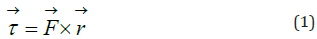 Were τ is torque (vector resulting of vectorial product),
F (vector) is load force (thorax+ abdomen weight) and r is
mechanical arm (vector). Equation 1 is a simplification because
there are mechanical reactions at trochanter caused by floor and
at the hip articulation for load, and regional muscle and ligaments
forces. The extremes of this physical arm are the femur head
and the trochanter. The hip biomechanical-load that makes the
torque-magnitude is exerted over the head. There is a synergism factor, statistically in an elderly patient: osteoporosis, muscles
and ligaments weakness, unexpected movements, or accidental
falling down. When the patient moves abruptly or falls for any
reason, the fracture could occur. Accordingly, the mathematical
models optimization/design constitutes an efficacious method
for sorting THA clinical difficulties and perform in vitro and in
vivo wear predictions. The continuous evolutions/improvements
in modelling, both analytical, numerical, hybrid and in finite
elements, is performed with the mathematical computational
bioengineering optimized for experimental data. A THA Taxonomy
of THA models was published in a contribution of this review [3].
In addition, along these previous contributions [1-4], a number
of optimization models were developed with computational
mathematical methods. In consequence, the principal objective of
this study was to obtain advances in an analytical model. This result
is the numerical determination of the K adimensionalconstant
parameter of the model for THA ceramic and metal. There are
individual patient THA clinical factors, and others external to
patients. In [1,3], a classification of clinical factors related to THA
surgery was developed. The PF-TCF Hip Arthroplasty Functional
Treatment Classification [1,3]. PF are defined as factors depending
on the patient, and TCF are defined as technical-clinical factors of
the hospital and/or traumatology-orthopedics service. Therefore,
the contribution novelty of this review is to sum up THA model
optimization to obtain/sort the orthopaedics and surgical clinical
difficulties. Numerical, 2D Graphical, 3D Interior and new 4D
Interior Optimization is presented sharing principal results [1-4].
Were τ is torque (vector resulting of vectorial product),
F (vector) is load force (thorax+ abdomen weight) and r is
mechanical arm (vector). Equation 1 is a simplification because
there are mechanical reactions at trochanter caused by floor and
at the hip articulation for load, and regional muscle and ligaments
forces. The extremes of this physical arm are the femur head
and the trochanter. The hip biomechanical-load that makes the
torque-magnitude is exerted over the head. There is a synergism factor, statistically in an elderly patient: osteoporosis, muscles
and ligaments weakness, unexpected movements, or accidental
falling down. When the patient moves abruptly or falls for any
reason, the fracture could occur. Accordingly, the mathematical
models optimization/design constitutes an efficacious method
for sorting THA clinical difficulties and perform in vitro and in
vivo wear predictions. The continuous evolutions/improvements
in modelling, both analytical, numerical, hybrid and in finite
elements, is performed with the mathematical computational
bioengineering optimized for experimental data. A THA Taxonomy
of THA models was published in a contribution of this review [3].
In addition, along these previous contributions [1-4], a number
of optimization models were developed with computational
mathematical methods. In consequence, the principal objective of
this study was to obtain advances in an analytical model. This result
is the numerical determination of the K adimensionalconstant
parameter of the model for THA ceramic and metal. There are
individual patient THA clinical factors, and others external to
patients. In [1,3], a classification of clinical factors related to THA
surgery was developed. The PF-TCF Hip Arthroplasty Functional
Treatment Classification [1,3]. PF are defined as factors depending
on the patient, and TCF are defined as technical-clinical factors of
the hospital and/or traumatology-orthopedics service. Therefore,
the contribution novelty of this review is to sum up THA model
optimization to obtain/sort the orthopaedics and surgical clinical
difficulties. Numerical, 2D Graphical, 3D Interior and new 4D
Interior Optimization is presented sharing principal results [1-4].

Materials and Optimization-Computational Methods
This section summarizes the most important material modelling selections along the recent contributions [1-4, 26]. First group is CoC materials and second one metals. Subsequently, the computational methods and algorithms used for both materials is presented. The difference between CoC and MoM algorithms is given by the parameter constraints and the algebraic changes in the objective function to obtain better charts in 2D Graphical Optimization and 3D Interior Optimization. An innovation related to those papers is the 4D Interior Optimization Method shown to close the section. The 4D Interior Optimization graphs are included in Results Section. Other improvement is a computational-software comparison with GNU-Octave System. 4D Interior Optimization graphics are presented and contrasted to Matlab images. Detailed data from ceramic/metal data selection is included in papers [1-4,26].
Materials
The necessary numerical data for ceramic optimization are hardness of CoC (hard bearings) materials, implant head standard diameter, experimental interval of erosion widely published in literature, units, and other complementary data which are mentioned but not implemented on this study model [14,5,7,17,18,21,22,27]. Their physical characteristics are detailed in Table 2. and unit’s database. Ceramic histocompatibility is usually good. The parameters/intervals for dual optimization and multiobjective optimization are included. For dual optimization, selected materials are Alumina (Al3O2), and Zirconium (ZrO2) Multiobjective optimization comprises Alumina, Zirconium, ZTA Biolox, and ZTA Biolox-Delta. Materials selected for dual metal optimization are Cast Co-Cr and Titanium alloy [1-4,9,17- 22]. Their physical characteristics are detailed in (Table 2). The material and corresponding experimental in vitro erosion data is taken from the literature [1-22,26]. In those studies, experimental metal wear intervals are implemented from [1-22]. In all cases, units were adapted on kg, mm, and mm3 criteria. Table 2 shows the material selection data within computational intervals. The reason is that actually there are variants of Titanium alloys, and Co-Cr [1-4]. Provided the units are set in mm, mm3, kg, and s, the standard K parameter of the model results adimensional [1]. These intervals are very important when setting numerical data into the simulation software.


Optimization-computational methods and algorithms
This section describes the general method and algorithm used for CoC and MoM [1-4,26]. Subsequently, specific mathematical constraints for CoC and MoM are presented. The method for dual and multiobjective optimization for ceramic THA and dual metal was previously published [1-4,29]. Algorithms implemented are based on classical Archard’s model [1,2,15,16,20,28], but with vector-matrix and units’ modifications [Casesnoves Algorithm, 2020-1]. A variant from this model with evoluted algorithms was developed in previous contributions [26]. In the literature, a linear type of the classical equation for wear optimization of hip implants without hardness reads,
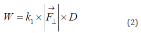
Where K1 is a constant that depends on hardness, F is load force (vector, and it is taken the normal component norm), and D is the sliding distance that depends on the velocity. There are several versions for this linear type of equation published studies [1-22,26]. However, it is considered the non-linear classical formula for these study objectives. The criterion is that hardness must be, for optimization precision, a separated parameter such as,
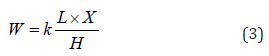
Where K is wear constant specific for each material, L biomechanical load (N, passed here to kg and mm), X sliding distance of the acetabular semi-spehere of the implant (mm), W is wear (mm3), and H is the hardness of the implant material (MPa, here it is used always kg and mm). In the literature [19], this K was set dimensional. In the reviewed publications, an adimensional K constitutes the practical innovation of the algorithms [1- 4,26]. Hence, setting vector calculus, for Inverse Least Squares optimization, minimize,
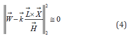
Subject to (generically and with vector-matrix calculus),
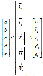
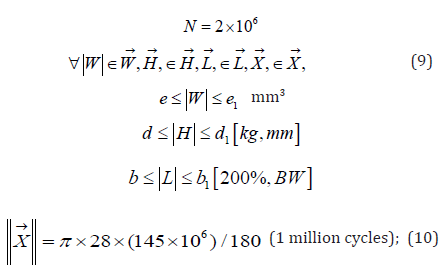
Where K is wear constant specific for each material, L biomechanical load (vector, N, passed here to kg and mm), X sliding distance of the acetabular semi-spehere of the implant (vector, mm), W is wear (vector, mm3), and H is the hardness of the implant material (vector, MPa, here it is always passed on to kg and mm). X is measured as the number of rotations of the implant multiplied by about half distance of its circular-spherical length. This formula was set both for CoC and MoM optimization [1- 4,26]. In the paper-reviewed group, X is approximated according to human biomechanics and kinesiology. The average rotation of femur head cannot reach 180° at any biomechanical movement in common patients. This is valid for flexion, extension, flexionrotation, extension-rotation, abduction, adduction, external/ internal rotation, or combinations of these [1-4]. For the program settings in [1-4], one cycle was taken as the length corresponding to the maximum kinesiologic rotation angle. Abduction, flexion and extension angles could be higher than average in special patients such as athletes or sporting individuals. The maximum femur rotation angle value is 145° in flexion. In the software, this magnitude was implemented. That is, Mc (million cycles) of rotation length is calculated: circumference implant-head radius R by π for a factor of angle of 145° and by 106. Therefore, the erosion in vitro data resulted from this optimization always has to be considered as the maximum angle possible. Number of rotations depend on the individual patient factors, [1-22]. The approximations for load for vector L for nonlinear optimization were a load-magnitude of around 200% of body weight (200%BW) [1-4]. Constraints for load are set from a 50kg patient till a 80kg patient. 50 kg corresponds, for example, to the body weight of a lightweight patient, or any elderly women who present a high incidence/prevalence of femur head fractures. It is recommended to read more mathematical details in all open access papers [1- 4]. The OF with L2 Norm that was used, [Casesnoves Algorithm, 2020-1], without fixed constraints reads,
minimize,
subject generically to,
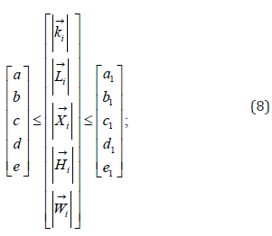
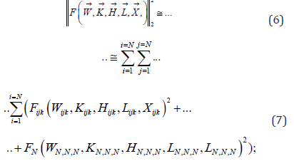
where the constraints values (a-e), are detailed in Table 4 for CoC and MoM. K is wear constant specific for each material, L biomechanical load (vector, N, passed here to kg and mm), X sliding distance of the acetabular semi-spehere of the implant (vector, mm), W is wear (vector, mm3), and H is the hardness of the implant material (vector, MPa, it was always passed on to kg and mm). Fortran 90, [24], GNU-Octave and Freemat were used to check/ validate the numerical precision of the numerical results and all graphics. 2D Graphical Optimization and 3D Interior Optimization methods in Matlab and GNU-Octave Systems are different programs compared to the numerical optimization ones. In every case, programming involves different structure, subroutines, and patterns. K is the principal variable for optimization. The reason is that with a multiobjective K parameter it is possible to carry out in vitro simulations in the materials selection process. The hardness for simulations in vitro, within the optimization hardness interval, could be therefore different from the ceramic / metal types of Tables 2,3. Therefore, the Inverse Least-Squares OF inverse algorithm [Casesnoves,2021,1,2,24] general formula implemented for constraints [1-4] (Table 4),
is minimize OF, subject to,


Equation 6 specific numerical numbers for constraints are detailed in (Table 4) for CoC and MoM. Provided this OF and constraints, running program time resulted be between 2-7 minutes-with a standard current microprocessor and pc memory. 3D Interior Optimization Matlab plots take longer time because there are 3D volume matrices, a number of nested arrays and patters compared to 2D Graphical Optimization. Scale factors are essential in both types of imaging subroutines and codes for sharp visualization [1-4]. Image processing and computer vision program-sentences and commands are essential to obtain good graphics. 3D Interior Optimization GNU Octave plots take longer time than MATLAB and provide with good computer vision imaging. GNU Octave Image Processing programs are set with different subroutines compared to Matlab but similar software, arrays, nested loops, and patterns than MATLAB [1-4,26].
Review of Results
The presentation of the results review is mainly graphical and numerical, divided into several subsections. The difference with papers [1-4] is the new development of 4D Interior Optimization with Matlab and GNU-Octave. All numerical data is included in Tables 5-8 and Figures 2-13. Further details can be found in [1- 4,26].


Dual and multiobjective CoC numerical results
Numerical results are detailed in Tables 5,6. The dual and multiobjective CoC nonlinear optimization for Alumina and Zirconium numerical results can also be obtained from graphics [1-4] with Matlab graphics cursor and Image Processing Tools.
DUAL MoM numerical results
The Numerical Optimization for MoM is included in Table 7. The numerical results, which are presented in Table 7, correspond to the subroutine optimization output. They can also be read/validated from graphics with Matlab. The optimal K value obtained is 28.9295×10⁻⁹ with residual 660.4426×10³. The optimal hardness obtained is 3.054×10⁶. Nonlinear Dual 2D Optimization matrix was set with 2 x 10⁶ functions . Running time was about 2–7 min to obtain local minima and graphics. As it occurred for THA ceramic modelling optimization [1-4], the exclusive existence of local minima is demonstrated. The proof that several local minima exist is got after multiple tentative optimizations with different initial search vectors along interval parameters. Among all of them, it was selected the best one with minimum residual. Residuals are low considering the 2 x 10⁶ OFs of the optimization matrix. Freemat [1-4,26] was used to verify 3D graphics and Fortran [1-4,26] for all numerical results. Note that the a dimensional K of MoM is one magnitude order higher than CoC K.


DUAL CoC imaging results
The CoC Dual Graphical Optimization results are presented a series of in graphics (Figures 2-7) show the model graphical optimization. The curves and areas correspond to model objective function (Y-axis) related to parameter values (X-axis). Nonlinear optimization matrix was set with 2 x 10⁶ functions. Running time was about 2-7 minutes to obtain local minima and graphics. The 2D surfaces obtained have all the OF values for these functions with all model parameters combined. Residuals are low considering the 2 x 10⁶ OFs of the optimization matrix.
Multiobjective CoC imaging results
in graphics Figures 2-7 show CoC graphical optimization of model for K. All parameters are in kg and mm (106 million cycles). As was made in CoC Dual Optimization, the matrix for all evaluated parameters in optimization program covers the 2D region along the graphics. The numerical result of the difference between model and experimental wear is at axis Y. For 2D Graphical Optimization, the matrix has all possible combinations of parameters, namely, load, hardness, and experimental wear. In the programs, the initial 3D volume-matrix, that is, a 3D matrix with 3 variables, hardness, load, and experimental magnitudes was converted with programming arrays to a 2D matrix of 2 million functions. Optimal K is 9.587464 x 10⁻⁹. Residual is 1.76697 x 10³ (Figure 7) shows 3D Interior Optimization to check the optimal K value. It illustrates also the inversely proportional relation between hardness and erosion magnitude. Volume-matrix array has 105 elements.


Dual MoM imaging results
These 2D and 3D optimization program(s) are based on nested arrays and a 3D volume-matrix with 105 and 106 elements, Figures 8-13, second program. For 2D Graphical Optimization, X-axis shows hardness, and Y-axis shows differences between experimental and model values [1-4]. For 3D Interior Optimization, X-axis shows K interval around optimal value obtained with optimization program, and Y-axis shows the hardness interval [1- 4]. All numerical values are expressed in mm, mm3, and kg. The software design was rather complicated [2,5,6,24].
4D CoC interior optimization
This new development does not corresponds to the series review. In Figure 12, a sketch showing 4D Interior Optimization is proven. Based on the same programming method than (Figures 10,11), a 4D graph for multiobjetive ceramic optimization is presented, Figure 12. 1D is the model wear, 2D is hardness interval, 3D is the adimensional K interval, and 4D is the model load. 4D corresponds to the vertical increase of the load in the graph block. Lower data means lower load, and upper higher one. To develop the 4D load image, it is necessary to include load interval within the 3D volume-matrix of the program pattern. In this way, it is clearly proven the tribology fundamentals: model-erosion is directly proportional to load and K, and inversely proportional to hardness. 4D Interior Optimization development in image processing depends of the particular model and the programming method.

4D CoC GNU-octave comparative interior optimization
Just the same, programming method was used from Figure 12 for GNU-Octave System. Recently, GNU Octave software shows a number of new imaging processing tools. These computer vision programming tools give a good quality images/graphs. Programming code in GNU Octave is similar to Matlab but different. It gives sharp images. Time for getting an image is about 30 seconds longer than Matlab. GNU Octave imaging tools are simpler than Matlab, but work correctly and fast. For setting a 3D image in GNU-Octave, there are several image-processing subroutines/options.
Numerical general-formula for results demonstration
The numerical results verification can be checked by two ways [1,4,26]. The first one is the 2D, 3D, and 4D graphics parameters and intervals that provide with numerical data distribution. The second is to check whether the model optimal values are within the experimental interval. To verify the numerical results the optimal values are implemented in the model, the general formula reads,
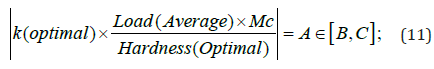
Where A is the numerical result of erosion of fitted model in mm3. B, C are the lower and upper limits of the experimental interval in mm3 (Table 8) shows parameters A, B, C for CoC Dual,CoC Multiobjective and MoM Dual Optimization. Accuracy of the model is good. Note that CoC Dual and Multiobjective Optimization have the same values because optimization interval comprises ZTA Biolox and ZTA Biolox Delta parameters [1-4].
Orthopedics and medical physics applications
Review of applications in traumatology surgery and orthopedics are presented along a series of reviewed contributions [1-4]. Hip articulation is rather a complex anatomical, physiological, and biomechanical system. The hip articulation biomechanical system is essential for locomotion and its biomechanical structure is significantly complex for kinematics and kinetics. In brief, the optimal hip biodynamics depends on two factors. First, one is the powerful muscles that perform the movement, walk and run mainly. Second is the strong ligaments that set the supporting forces to control correctly the muscles contraction/ relaxation and create constraints to guide and support/prevent/ resist any biased movement. Main ventral muscles for walk and run that create hip rotation cycles are Psoas Major and Minor, Iliacus, Abductor Longis and Adductors system. At dorsal, Gluteus group is essential for locomotion. Most important ligaments are Iliofemoral (supporting), Pub femoral (resisting), Iliolumbar (limiting), and Ischiofemora (resisting). In plain language, hip joint resembles a sophisticated-precise locomotion human machine with a wide range of movements/biodynamics. The energypower is provided by the muscle system, while the ligaments and bones constitute the biomechanical frame structure. This biodynamical system has been genetically optimized during the human evolution along million years. Therefore, it is difficult to synopsize the applications in a simple taxonomy-format. Here is intended to summarize the principal findings and set a new classification/perspective for the optimized model usage-that can be extrapolated to other articulation models. There are two main groups of applications. The first is the biotribotesting in vitro itself/exclusively, Table9. The second comprises two strands: applications for THA improvements, and applications to avoid/ minimize THA complications, Table 10. Literature for pre-surgery and post-surgery THA pathology is profuse [1-17]. Laboratory applications are tribotesting predictions for wear rates, no matter what type of apparatus/experimental-system is used. For every experimental data obtained, model can be improved. The possibility to design new models based on the initial one is other chance Table 9 summarizes all these perspectives. For practical medical industrial applications, the advantage of the demonstrated model is its simple non-linearity and adimensional K. That is, in engineering medical devices production the common method is to set as simpler as possible for manufacturing, avoiding complex equations. As a cautious and tentative surgical pre-hypothesis, THA normality restoration is a multifunctional clinical subject, depending on a number of synergic-interactive factors. Therefore, the second group of applications is more difficult to abbreviate, because both THA improvements and THA complications prevention depend on multifunctional factors [1- 4]. Besides, these factors are synergic one another. For example, post-operation increase of THA wear causes a post-operation biomechanical problem and viceversa [1-4]. Other factor, for instance, could be a post-operation deformation (cause) by osteoporosis, that could result (effect) in wear increase or THA malfunction [1-17]. Therefore, there are two main surgicalpathology concepts: cause and effect. Namely, if cause were aware post-operation increase for defective THA device lab design, the effect would be a biomechanical partial/total failure. Conversely, if a biomechanical post-operation complication cause occurs (increase of osteoporosis, osteonecrosis, biomechanical injury, etc.), the effect would be an increase of THA wear symmetric, non-symmetric, with/without cracks etc. Table 10 sums up all these possibilities/ ideas. It shows causality and multi-effect links for improvements and complications prevention. Literature and clinical case reviews are profuse in this matter [1-17].


Discussion and Conclusion
In a series of articles [1-4,26], the objective to get a nonlinear optimized model for wear of THA CoC and MoM implants was developed. The nonlinear optimization was Numerical, 2D Graphical, 3D Interior, and 4D interior Optimization. The innovation of this review contribution is the 4D Interior Optimization improvement—with a software comparison to Matlab System. The principal achievement is an adimensional K for the model that gives accuracy for THA tribotesting in vitro predictions. The K result can be considered acceptable and efficacious, provided the in vitro erosion intervals of the literature [refs]. The method was the classical Inverse Least-Squares technique. This method is efficient and accurate [1-4]. An inconvenient of the model is that has not global minimum, instead multiple local minima. The computational assessment between Matlab and GNU-Octave Systems for 4D Interior Optimization confirm the precision of the optimized model. The accuracy of the fitted model is almost equal for CoC and MoM parameter intervals. However, the optimization for CoC has wider intervals as it was both Dual and Multiobjective. 3D and 4D imaging results show be satisfactory for Mat lab abd GNU Octave in sharpness, contrast, and clarity. Both systems Image Processing Tools can be considered up to standards. Programming software for 1D-4D Computer Vision was rather difficult since large-dimension volume-matrices in arrays had to be built—with 105 and 106 elements. Therefore, the objectives of the studies [1-4] were found acceptable and useful. The results comprise two widely used THA materials, ceramic and metal. Numerical results, 2D Graphical, 3D Interior, and 4D Interior Optimization are adequate. The utility of the results is mainly focused on extrapolated simulations/predictions of erosion rates for in vitro THA studies. Different materials within the selected parameter-interval ranges can be set in the model whose optimal parameters are calculated along these studies. Improvements in algorithms, software, and model design are feasible from these findings. Improvements optimization method new 4D Interior Optimization Method emerge from the summary of the paper series. From these findings, both numerical and graphical methods can be applied on similar models, not limited to clinical bio tribology.
The contribution of these articles [1-4,26] in predictive wear methods is focused on in vitro experimental computational erosion determinations. This means that the numerical adimensional K and optimal hardness intervals for this model could be used as an exact/approximated reference to obtain tentative data when planning a laboratory experiment. Setting K as an adimensional model-constant makes the tribotesting task easier with the selected units implemented within the model. Medical industrial applications comprise the advantage of the demonstrated model for its simple non-linearity and adimensional K. In other words, for clinical medical physics devices production the usual technique is to use as simpler as possible for manufacturing, avoiding complex physics equations. In brief, the reviewed series of contributions suppose an improvement for THA in vitro tribo testing with THA CoC and MoM clinical Medical Physics and Bioengineering useful applications.
Scientific Ethics Standards
This review article summarizes methods and results from a series of contributions [refs]. The difference is the new inclusion of 4D Interior Optimization innovative technique. Therefore, graphs and ideas from a group of articles are taken in. 2D/3D Graphical- Optimization Methods were created by Dr Francisco Casesnoves on December 2016 and Interior Optimization Methods in 2019. Author originally developed this software. This article has a few previous paper information, whose inclusion is essential to contribute understandable. One applications section paragraph related to biomechanics of hip is taken from an upcoming article, as it clarifies the clinical usage sharply. The nonlinear optimization software was improved from previous contributions in subroutines modifications, patters, loops, graphics and optimal visualization with GNU Octave new software. This study was carried out, and their contents are done according to the European Union Technology and Science Ethics. Reference, ‘European Textbook on Ethics in Research’. European Commission, Directorate-General for Research. Unit L3. Governance and Ethics. European Research Area. Science and Society. EUR 24452 EN [29,30]. In addition, based on ‘The European Code of Conduct for Research Integrity’. Revised Edition. ALLEA. 2017. This research was completely done by the author, the computational-software, calculations, images, mathematical propositions and statements, reference citations, and text is original for the author. When a mathematical statement, proposition or theorem is presented, demonstration is always included. The article is exclusively scientific, without any commercial, institutional, academic, political, or economic influence. When anything is taken from a source, it is adequately recognized. Ideas from previous publications were emphasized due to a clarification aim [29-30].
References
- Casesnoves F (2021) Mathematical Standard Parameters Dual Optimization for Metal Hip Arthroplasty Wear Modelling with Medical Physics Applications. Standards 1: 53-66.
- Casesnoves F (2021) Nonlinear Inverse Dual Optimization for Hip Arthroplasty Ceramic Materials. AJMS (Asian Journal of Mathematical Sciences) 5(1): 53-61.
- Casesnoves F (2021) Multi objective Optimization for Ceramic Hip Arthroplasty with Medical Physics Applications. Int J Sci Res Comput Sci Eng Inf Technol 7: 582-598.
- Casesnoves F (2018) Nonlinear comparative optimization for biomaterials wear in artificial implants technology.
- Merola M, Affatato S (2019) Materials for Hip Prostheses A Review of Wear and Loading Considerations. Materials 12: 495.
- Navarro N (2008) Biomaterials in orthopedics. J R Soc Interface 5: 1137-1158.
- Bono V, Colls (1999) Revision Total Hip Arthroplasty. Springer.
- Abdel M, Della Valle C (2017) Complications after Primary Total Hip Arthroplasty. Springer.
- Learmonth I (2000) Interfaces in Total Hip Arthroplasty. Springer.
- Kurtz S (2014) Advances in Zirconia Toughened Alumina Biomaterials for Total Joint Replacement. J Mech Behav Biomed Mater 31: 107-116.
- Sachin G, Mankar A (2016) Biomaterials in Hip Joint Replacement. Int J Mater Sci Eng 4: 113-125.
- Li Y, Yang C, Zhao H, Qu S, Li X (2014) New Developments of Ti Based Alloys for Biomedical Applications. Materials 7: 1709-1800.
- Kolli R, Devaraj A (2018) A Review of Metastable Beta Titanium Alloys. Metals 8: 506.
- Holzwarth U, Cotogn G (2012) Total Hip Arthroplasty. JRC Scientific and Policy Reports European Commission Brussels.
- Delimar D (2018) Femoral head wear and metallosis caused by damaged titanium porous coating after primary metal-on-polyethylene total hip arthroplasty A case report. Croat Med J 59: 253-257.
- Zhang M, Fan Y (2015) Computational Biomechanics of the Musculoskeletal System. CRC Press Boca Raton FL.
- Dreinhöfer K, Dieppe P, Günther K, Puhl W (2009) Eurohip Health Technology Assessment of Hip Arthroplasty in Europe. Springer.
- Casesnoves F (2018) 2D computational numerical hardness comparison between Fe based hard faces with WC Co reinforcements for Integral Differential modelling. Trans Tech 762: 330-338.
- Hutchings I, Shipway P (2017) Tribology Friction and Wear of Engineering Materials. (2nd Edition), Elsevier, Amsterdam, Netherlands.
- Shen X, Lei C, Li R (2010) Numerical Simulation of Sliding Wear Based on Archard Model. International Conference on Mechanic Automation and Control Engineering 26-28.
- Affatato S, Brando D (2012) 1-Introduction to Wear Phenomena of Orthopedic Implants. Woodhead Publishing.
- Matsoukas G, Kim Y (2009) Design Optimization of a Total Hip Prosthesis for Wear Reduction. J Biomech Eng 131: 051003.
- Casesnoves F, Antonov M, Kulu P (2016) Mathematical models for erosion and corrosion in power plants A review of applicable modelling optimization techniques. RUTCON2016 Power Engineering Conference.
- Galante J, Rostoker W (2014) Wear in Total Hip Prostheses. Acta Orthop Scand 43: 1-46.
- Casesnoves F (2012) Computational Simulations of Vertebral Body for Optimal Instrumentation Design. ASME J Med Devices 6: 021014.
- Casesnoves F (2018) Mathematical Models and Optimization of Erosion and Corrosion. Tallinn, Estonia.
- Jennings L (2012) Enhancing the safety and reliability of joint replacement implants. Orthop Trauma 26: 246-252.
- Casesnoves F (2007) Large Scale Matlab Optimization Toolbox (MOT) Computing Methods in Radiotherapy Inverse Treatment Planning. High Performance Computing Meeting.
- (2021) European Textbook on Ethics in Research. European Commission.
- ALLEA (2017) The European Code of Conduct for Research Integrity. ALLEA Berlin Barndenburg Academy of Sciences.
- Mattei L, Di Puccio F, Piccigallo B, Ciulli E (2011) Lubrication and wear modelling of artificial hip joints A review. Tribol Int 44: 532-549.
- Casesnoves F (2019) Die Numerische Reuleaux Methode Rechnerische und Dynamische Grundlagen mit Anwendungen (Erster Teil). Sciencia Scripts.
- Kulu P, Casesnoves F, Simson T, Tarbe R (2017) Prediction of abrasive impact wear of composite hard facings Solid State Phenomena Trans Tech Publications 267: 201-206.
- Saifuddin A, Blease S, Macsweeney E (2003) Axial loaded MRI of the lumbar spine. Clin Radiol 58: 661-671.
- Damm P (2014) Loading of Total Hip Joint Replacements.
- Casesnoves F (2019) The Numerical Reuleaux Method a Computational and Dynamical Base with Applications. Lambert Academic Publishing.
- Casesnoves F (2007) A Monte Carlo Optimization method for the movement analysis of pseudo rigid bodies.
- Casesnoves F (2011) Theory and Primary Computational Simulations of the Numerical Reuleaux Method (NRM) Casesnoves Francisco. Int J Math Computation 13: 89-111.
- Casesnoves F (2015) Applied Inverse Methods for Optimal Geometrical Mechanical Deformation of Lumbar artificial Disks/Implants with Numerical Reuleaux Method 2D Comparative Simulations and Formulation. Comput Sci Appl 2: 1-10.
- Casesnoves F (2018) Inverse methods and Integral Differential model demonstration for optimal mechanical operation of power plants numerical graphical optimization for second generation of tribology models. Electr Control Commun Eng 14: 39-50.
- Casesnoves F, Surzhenkov A (2017) Inverse methods for computational simulations and optimization of erosion models in power plants. IEEE Proceedings of RUTCON2017 Power Engineering Conference.
- Abramobitz S (1972) Handbook of Mathematical Functions. Appl Math Ser 55.
- Luenberger GD (2008) Linear and Nonlinear Programming. Springer.
- Casesnoves F (2016) Exact Integral Equation Determination with 3D Wedge Filter Convolution Factor Solution in Radiotherapy. Series of Computational Programming 2D-3D Dosimetry Simulations. Int J Sci Res Sci Eng Technol 699-715.
- Panjabi M, White A (1980) Clinical Biomechanics of the Spine. Lippincott 42: S3.
- Casesnoves F (2021) Software Programming with Lumbar Spine Cadaveric Specimens for Computational Biomedical Applications. Int J Sci Res Comput Sci Eng Inf Technol 7: 7-13.
- Surzhenkov A, Viljus M, Simson T, Tarbe R, Saarna M, et al. (2017) Wear resistance and mechanisms of composite hard facings at abrasive impact erosion wear. J Phys 843: 012060.
- Barker P (2014) The effect of applying tension to the lumbar fasciae on segmental flexion and extension. 5th International Congress of Low Back and Pelvic Pain 50-52.
- Galme S, Barker P, Bhalerao Y (2016) Biomaterials in Hip Joint Replacement. Int J Mater Sci Eng 4: 113-125.


