


Analysis of Instrumentation Screw-Engine with the use of Automatic Systems
Kirill Epifantsev*
1Saint-Petersburg State University of Aerospace Instrumentation, Russia
Submission: February 12, 2018; Published: February 19, 2018
*Corresponding author: Kirill Epifantsev, Saint-Petersburg State University of Aerospace Instrumentation, Russia, Tel: +79633437759; Email: epifancew@gmail.com
How to cite this article: Kirill E. Analysis of Instrumentation Screw-Engine with the use of Automatic Systems. Curr Trends Biomedical Eng & Biosci. 2018; 12(005 3): 555840. DOI: 10.19080/CTBEB.2018.12.555840
Abstract
This environmental situation is a national priority. The Decree of the President of the Russian Federation dated 5 January 2017 announces 2017 the Year of Ecology in Russia. Most environmental reforms stipulated by amendments to laws are enacted from 1 January 2017. These are primarily measures aimed at emissions and discharges control using best available technologies and breakthrough provisions of the Industrial and Consumer Waste law [1-4]. An alternative to waste incineration is municipal waste recycling by moulding in extrusion machines to make pellets to be further used in the fuel or construction industries. The profitability of a waste recycling facility is dependent on a sound choice of extrusion equipment with the best value for money [5].
Introduction
An increase in the reliability of extrusion machines used to shred and extrude refractory materials (plastics, hard food waste, and couched paper) is subject to rational use of the extrusion force inside the machine frame. It requires automatic gauges and mechanisms capable of seamlessly increasing or reducing the effort and rotation speed at the right time to preserve the engine life and prevent failures.
When producing fuel pellets or construction materials from waste, an extrusion machine is exposed to significant loads on its main operating elements such as: inside the frame, on the auger shaft, coupling, connecting auger to the engine shaft, and inside the matrix.
The above loads need to be reduced to not only minimise machine assembly wear but to reduce power consumption, and enhance the reliability of the engine which accounts for 30% of the machine value. Currently, the set-up of a waste recycling facility requires a thorough review of power consumption per 1kg of product. Energy saving on the machine makes extrusion equipment more affordable in regions with high energy cost.
An operating body of the auger machine is an auger rotated by the engine through a box coupling. Clogging increases pressure from a moulded feed both on a welded auger head (Figure 1-3) and on the box coupling. These are main machine operating elements, and a reduction in their strength will result in the production of defective pellets (less tight and more friable).

The most common deformed elements of the auger machine when clogged: 1 - weld location of an auger head and shaft, 2 - box coupling on the rotation shaft Statistically, without engine emergency shutdown, these elements develop microcracks and are deformed. Twisting deformation can be assessed as twisting of a beam with a non-round cross-section. If we consider an auger to be a circle with a flattened surface, the maximum effort is applied at the middle of the flat cut: xmax = h/2 [6,7], i.e. the maximum effort is in the middle point at the location where the auger diameter changes and the auger has a cone shape.
We will calculate the moment of resistance for the maximum overload force at the shaft when it is clogged and a contingency situation develops [8].
Therefore, estimates were sufficient to determine the moment of resistance as 238.04kN/m. When exceeded, the auger would be exposed to microcracks and deformation.
Materials and Methods
The extrusion moulding process was studied using waste from dumps and wastewater treatment facilities, non-marketable TPP products and wood processing waste [9]. Clogging processes were researched using a newly built auger-type machine (MN-3) with heating elements.
The ingredients of the mixture to be palletised with a moisture content of 45% were as follows:
I. 20% of cardboard;
II. 15% of plastic;
III. 40% of coal charge;
IV. 10% of sawdust; and
V. 15% of waste from the wastewater treatment facilities (sludge).

The feed was loaded into the hopper of MN-3 auger-type machine which started to produce pellets 20 minutes after pre-heating of its heating elements and ramp-up. The process was going for two hours when machine performance began to decrease. The auger rotation speed was increased using a frequency converter, but that raised power consumption by 20%. After three hours of operation, a decision was made to shut the machine down since its performance was minimum with the maximum rotations per minute of the engine (Figure 4).
During the experiment, the frequency converter helped to control engine and, therefore, auger rotation speed. However, speed was adjusted manually by an operator depending on pellet output. Clogging of the auger was not controlled since it was mounted in a metal frame and the process could not be seen. Such actions were random and chaotic. Temperature was not switched off, either, heating bundles were operated in the normal mode so that the edges of the clog in the auger melted and became harder. When the frame was dismantled, the cause of the loss of efficiency could be identified. It was a clog consisting of a compacted waste feed which blocked the auger and resulted in the emergency shutdown (Figure 5 & 6).

A decision was made to study the clog at the destructive press:
I. For uniaxial compressive strength test;
II. For split test; and
III. To determine a normal effort at the auger shaft in ParaView software by comparing it to the estimated effort of 238.04kN and to visually monitor the clogging process (Table 1).

This data was needed to determine the range of action of a pressure gauge to be later mounted in the extruder frame to alarm of the start of the clogging process. By interacting with the frequency converter, the gauge will prevent emergency shutdown which reverses the engine through a change in poles. A shaker may also be used inside the auger to reduce stock adhesion to the auger and prevent clogging.
Results

The uniaxial compressive strength test required to split the clog mechanically into two parts to prepare for testing at Testometric 500 press in the Geomechanics and Mining Issues Centre of the Mining University. The diameter and height of produced samples were duly measured (Figure 7).

A cone sample (Sample 1) was compressed at the press first followed by a cylinder sample (Sample 2) (Table 2). Figure 7 shows graphically how changes in deformation (mm) depend on the load (N). Sample 2 apparently has better performance (by 881.3 N) as compared to Sample 1. Deformation of Samples 1 and 2 during uniaxial compressive strength test. These were followed by the uniaxial compressive strength tests of produced pellets (Figure 8 & Table 2). Clogging was analysed then in a 3D simulation model of the extrusion machine in ParaView software. The simulation included similar machine parameters with its matrix split using the finite elements method. A type of an approximation function is randomised per element. The simplest case is linear polynomial (Figure 9).


Simulation of the clogging process
The studies completed revealed several important parameters required to set automatics cutoff values:
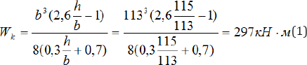
1) Moment of resistance of the auger according to Formula 1 is 297kN/m. When it is exceeded, the auger is subject to microcracks and deformation. When simulated in ParaView software, the moment at the auger shaft during clogging reaches 324.46kN. In this case, we will take the effort range between 297 and 324.460kN;2) Uniaxial compressive strength test shows the difference between the cone and cylinder parts of the auger as 3,907.6N and 4,788.9N, which demonstrates the difference of 800N and supports I.N. Chisty’s theory [10,11] of pressure summation in the middle point of the cone output (P+EP) after which the clog is hard to destroy (Figure 10).

Visual representation of pressure summation inside the matrix. This experiment enabled to determine the pressure summation point as 115cm- the length of the cone part of the clog (Table 1). It is the point where a leap certifying to clogging takes place. The experiments facilitated the collection of information on clog location and hardness in different parts. The studies formed the basis for the upgrade of the existing MN-3 extruder which was re-equipped with pressure gauges 115cm off the matrix edge and a strain gauge capable of recognising an effort on the auger between 297 and 324.5kN. The main function of the two gauges is to start auger in the reverse for the clog to "roll away' and destroy. The auger was also upgraded with a vibrating element reducing feed stuck to the coils and minimising clog development and matrix clogging.

This area of research will be effective means of creating "transparent" extruder control systems for automatic monitoring of the clogging process and protection against machine breakdown and loss of reliability.
At extrusive processing chosen by us for the analysis the processed material is exposed to intensive termal, waterand mechanical influence which leads to various changes in its components [1]. The structure for the formation of peat was analysed on the example of peat pellets using a microscope ZEISS-Axiolab (clearance 4,724 mm), Figure 11, 12. Investigated raw materials - the field N2, Tver region. Then the prepared sample initial mass of 39.8 g was hot at a temperature of 900°C for 8 hours. After calcination, the samples were subjected to x-ray fluorescence analysis. The results are presented in Figure 11a-12a. The analysis of graphs shows that for light elements in samples 1 and 2 contained mainly K, P, CA, Cl and Si. The average elements in samples 1 and 2 are Zn, Fe, Cu, Mn and Sr. There are very heavy element Sr. Therefore, to download in the bunker and in the production of biofuels it is necessary more carefully to analyze raw materials to reduce environmental risk during the subsequent combustion of the finished fuel [2].

Acknowledgement
The results of this work were marked on the Competition for the best scientific work about Earth (Tomsk Polytechnic University, 2012); Grant Competition of scientific works of graduate students (Government of St. Petersburg, 2012); Grant of the German Academic Exchange Service (DAAD 2012); The grant for young scientists (Government of St. Petersburg, 2016).
References
- Environmental Protection, 2012-2020, National Programme of the Russian Federation/Ministry of Natural Resources and Ecology of the Russian Federation.
- Final Report on the Waste in Russia: Garbage or a Valuable Resource? Scenarios of Development of the Municipal Solid Waste Handling Sector // International Financial Corporation (IFC, World Bank Group).
- Federal Law dated 24 June 1998, No. 89-FZ (rev. dated 28 December 2016), Industrial and Consumer Waste / Consultant Plus.
- Clean Country priority project profile/Government of the Russian Federation [electronic resource].
- Nikulin AN (2014) The research of possibility to use the machine for biofuel production as a mobile device for poultry farm waste recycling. Life Science Journal 11(4): 464-467.
- Kocserha I (2010) Effects of Extruder Head's Geometry on the Properties of Extruded Ceramic Products. Materials Science Forum 659: 499-504.
- Benbow J (1993) Paste Flow and Extrusion. Clarendon Press, Oxford UK, p. 425.
- Bogatov BA (1985) Managing peat bog development. Higher School, p. 168.
- Epifancev K (2013) Modeling of peat mass process formation based on 3D analysis of the screw machine by the code YADE / K. Epifancev. American Journal of Mechanical Engineering 1(3): 73-75.
- Chisty IN (1980) Granulated peat production. Minsk, p. 420.
- Kosov VI (2005) Peat and organic slime as a powerful energy and geoecological potential of Russia. Exploration, production, and refining of minerals, Interment Engineering, pp. 212-223.


