3D-Design of Artificial Mandible Using CBCT, CAD and FEA
Salah HR Ali12*, Adel A El-Ashry2 and M-Naeem Assasa2
1Department of Engineering and Surface Metrology, National Institute for Standards, Egypt
2Department of Engineering Sciences and Technology, Misr University for Science & Technology, Egypt
Submission: March 01, 2017; Published: August 29, 2017
*Corresponding author: Salah HR Ali, Department of Engineering and Surface Metrology, National Institute for Standards, Egypt, Tel: 20-11-20121545; Email: SalahAli20@yahoo.com
How to cite this article: Salah HR A, Adel A E A, M Naeem A. 3D-Design of Artificial Mandible Using CBCT, CAD and FEA Curr Trends Biomedical Eng & Biosci. 2017; 8(2): 555732. DOI: 10.19080/CTBEB.2017.08.555732
Abstract
Natural bone is an essential biomaterial includes collagen fibers, Hydroxyapatite nano crystals and proteoglycans in nano scale. Engineering design of artificial mandible is challenging processes due to complicated geometrical shape and dimensions of structure. Artificial mandible should be similar and close to the shape and function of the original human mandible. Modern improvements in biomaterials and computational technology made advances and developments in computer aided design/computer aided manufacturing (CAD/CAM) technology with the help of other technologies such as cone beam computed tomography (CBCT), finite element analysis (FEA). Artificial mandible can now be designed, analyzed, and manufactured easily, accurately and faster to satisfy the patient needs. This paper reviews and discusses the important processes and limitations of 3D-design and analysis for artificial mandible using CAD, CBCT image processing and FEA techniques. Inorder to understanding and insure how the mechanical design and computer aided design with computer aided manufacturing technologies are used for optimal design and analyses. Moreover, how the combination of the modern technologies leads to improvement and enhancement in the subject area of mandible bone replacement.
Keywords: 3D-Design; Biomaterials; Dimension and shape; Mandible; CBCT; CAD; FEA techniques
Introduction
The human body is formed of many parts with a very complex form and geometrical structure. The parts are the same in each human but different in geometrical features, dimensions and physical mechanical properties [1]. Mandible (lower jaw) is one of fourteen facial bones. It is an exceptional bone, the largest and strongest bone which helps in protecting facial organs, house of the lower teeth and the only movable bone in the head [2,3]. Mandible motion is supported by four muscles for mastication, masseter, temporails, medial pterygoid, and lateral pterygoid [4]. Accidents may cause numerous fractures in the human bone such as mandible fracture. It is one of the most common due to its position in the facial skeleton, fractures types depend on the mechanism of the injury [2]. So the scientists try by using different technologies to maintain the same look and function of damaged parts while achieving patient satisfaction. To deal with the fractures and find a way to reconstruct and fabricate the mandible, we need to increase our knowledge and hope to understand the methods of designing and analyzing the human mandible, which is needed by other technologies to reconstruct the lower jaw such as 3D printing technology. Therefore, in this work, we will discuss the following topics:
1. Data acquisition using Cone beam Computed tomography scan (CBCT)
2. Image processing techniques and software
3. The CAD software being used for this technology
4. Finite element analysis (FEA) using biomaterial
5. Manufacturing process using Rapid Prototyping Technology
This paper aims to understand and increase the background of design and analyses for the mandible to be ready for fabrication for implanted in the body replacing the original damaged mandible. Moreover, the work aims to understand what nanotechnology various on design and applications in the field of bone replacement and reconstruction.
Material and Methods
Biomaterials
Biomedical materials plays the main role in replacing and improving the function of human body, such as skeletal, circulatory, nervous systems and some implants like bone, joint replacements, artificial heart valves, dental implants and contact lenses [5]. Biomaterials must be capable of being used in human body without causing a rejection response from the surrounding body tissues, strict tests should be made to make sure that they will not cause inflammation, infection, adverse immunological response or any other complication. There are materials that are specially used for medical applications, as in prosthesis and implants. From a scientific point of view, this field still hasn't achieved its maturity, hence, inventions and discoveries are constantly made. In 1983, titanium was first used for medical implants and prosthesis by Luckey & Kubli [6]. Titanium plates have the advantages of being much more biocompatible and mechanically similar to bone than other metals, it is preferred for medical devices because of its properties: light weight, high strength, they are also compatible with magnetic resonance imaging and computed tomography imaging procedures. The most well-known chemical property of titanium is its exceptional resistance to corrosion, because it is biocompatible (non-toxic and is not rejected by the body), titanium is used in a number of medical applications including surgical implements and implants [1-6]. There are different common classification types of biomaterials implanted with human biological system. Biomaterials are classified into two main categories [5,7]. The first category is based on natural biomaterial created by Allah, while the second category is based on synthetic biomaterials. With the advanced technology of engineering biomaterials tissues, a new third category is created called combined of biomaterials. This type plays between these two categories. Examples of some types of biomaterials applications are
1. Nano Hydroxyapatite for orthopedic implants and drug carriers for bone diseases,
2. Carbon nano tubes and nano fibers as novel drug delivery devices,
3. Gold nanoparticles for cancer diagnostics and
4. Quantum dots as biological sensors.
The use of carbon nano tubes and various types of nanoparticles in medicine is very prevalent in research [8-11]. The biomaterial properties of the mandible can be obtained using Hounsfield units (HU) method. The electron density is obtained from the CT-scanner via so-called Hounsfield units (HU) defined as follows:
HU=1000((μ-μ_water)/μ_water )
Where μ referred to the linear attenuation coefficient for the respective material compared with water. The linear attenuation coefficient depends on parameters such as electron density, atomic number and the beam quality of the CT-scanner. The Hounsfield unit (HU) is a quantity commonly used in computed tomography (CT) scanning to express CT numbers in a standardized and convenient form. Hounsfield units, created by and named after Sir Godfrey Hounsfield, it is obtained from a linear transformation of the measured attenuation coefficient. This transformation is based on the random definitions of air and water [12].
Methods
CAD is a modeling process includes three major phases: image acquisition, imaging process and three dimensional (3D) reconstructions to form voxel-based volumetric image representation are using for design the model. Furthermore, the obtained CAD model will be fabricated using rapid prototyping (RP) technology [9-12]. An overall procedures of the imaged based CAD modeling is illustrated in (Figure 1).

Data acquisition
A coned beam computed tomographic (CBCT) scan of patient mandible is obtained for data acquisition [12]. CBCT is one of the newest medical imaging techniques that generate 3D images. This imaging technique is based on a cone-shaped X-ray beam centered on a 2D detector that performs one rotation around the object, producing a series of 2D images [10-12]. These images are reassembled in 3D by the modification of the original cone-beam algorithm developed by Feldkamp et al. [13]. When one is comparing, or evaluating an emerg-ing technology, it is preferred to be compared to the existing gold standards. Currently, conventional medical CT is the standard for many radiological examinations. Cone Beam CT differs from the conventional CT scanning technology in many areas, the patient sits in an upright position instead of lying down as in conventional CT, scanning time is 18 seconds which is faster than the conventional CT [14], a study reported that the effective radiation dose of the CBCT is within 36.9 and 50.3 microsievert, which gives that radiation dose is 97% lower than conventional CT, the dose is effected by many factors such as the patient size, field of view, region of interest, and resolution. In addition, Ludlow and Ivanovic conducted comprehensive evaluations of the effective doses of various CBCT units based on the 1990 and 2007 recommendations of the International Commission on Radiological Protection (ICRP) [15]. They found that calculated doses were much higher when using the new guidelines, which resulted in 68-1073μSv for large field of view (FOV), 69-560μSv for medium FOV, and 189-652μSv for small FOV. This study also confirmed that a similar-FOV medical CT produced a higher dose than CBCT Based on the 2007 ICRP report, the effective dose from panoramic radiography was ap-proximately 13μSv, from cephalometric radiography is 1-3μSv, and from periapical radiography is 1-8μSv. Overall, the radiation dose from a CBCT is lower than that from a conventional CT, but is significantly higher than traditional dental radiography techniques as shown in (Table 1).

Where μSv is a microsievert which indicates the radiation dose unit.
CBCT has a higher resolutions and good quality because it can generate a size of a voxel (a 3D cuboid unit of images) with dimensions as small as 0.125mm. It is commonly used for treatment planning of orthodontic issues [16]. CBCT is useful for more complex cases that involving the following [17]:
1. Surgical planning for impacted teeth.
2. Diagnosing temporomandibular joint disorder (TMJ).
3. Accurate placement of dental implants.
4. Evaluation of the jaw, sinuses, nerve canals and nasal cavity.
5. Detecting, measuring and treating jaw tumors.
6. Determining bone structure and tooth orientation.
7. Locating the origin of pain or pathology.
8. Cephalometric analysis.
9. Reconstructive surgery.

Medical image processing
The data obtained from the CBCT scan is applied to a medical image processing software such as (Mimics, Analyze Direct), for point cloud data processing. A Point Cloud is a set of data points in some coordinate system. In 3D coordinate system, the points are usually defined by X, Y, and Z coordinates, and used to represent the external surface of an object. Point clouds may be created by 3D scanners [10-12] Figure 2 shows the steps of surface model construction of mandible using reverse engineering (RE) software [12]. Materialize Mimics can be used for import DICOM, JPEG, TIFF, BMP, and x-ray or raw image data. Mimics can easily and quickly create accurate 3D model. A 3D model is shown in Figure 3 which exports the 3D models for 3D analysis using FEA, meshing, design [18]. For Analyze direct software it provides a versatile and powerful array of display tools for image review and visualization, and it allows for in-depth statistical analysis of data with a suite of robust measurement tools. Even though there are loads of other image processing programs but those are the most commonly used cause the can be easily used and have high collection of display tools [19]. Image processing software provides lots of techniques in order to process, enhance, and reduce the image noise. The various techniques are listed as follows[9-11,20]
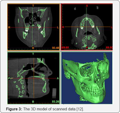
Image processing and enhancement: Image data recorded by sensors contains errors related to geometry and brightness values of the pixels. Image enhancement is the modification of image by altering the pixel brightness values to improve its visual effect. The enhancement process itself does not increase the characteristic information content in the data; it simply emphasizes certain detailed image characteristics. It involves a collection of techniques, which are: contrast Stretching, noise filtering and histogram modification.
Image segmentation: Segmentation is one of the main problems in image processing; it is a process that divides an image into its basic parts or objects. The level to which this part is carried out depends on the problem being solved; the division should stop when the objects of interest in an application have been isolated. Image thresholding techniques are used for image segmentation.
Feature extraction: This technique extracts high-level features needed to achieve organization of targets. Features are those items which uniquely describe a target, such as size, shape, composition, location etc.
Image classification: It is labeling of a pixel or a group of pixels based on its grey value. Classification is one of the most often used methods for information extraction.
Solid modeling of mandible using CAD software
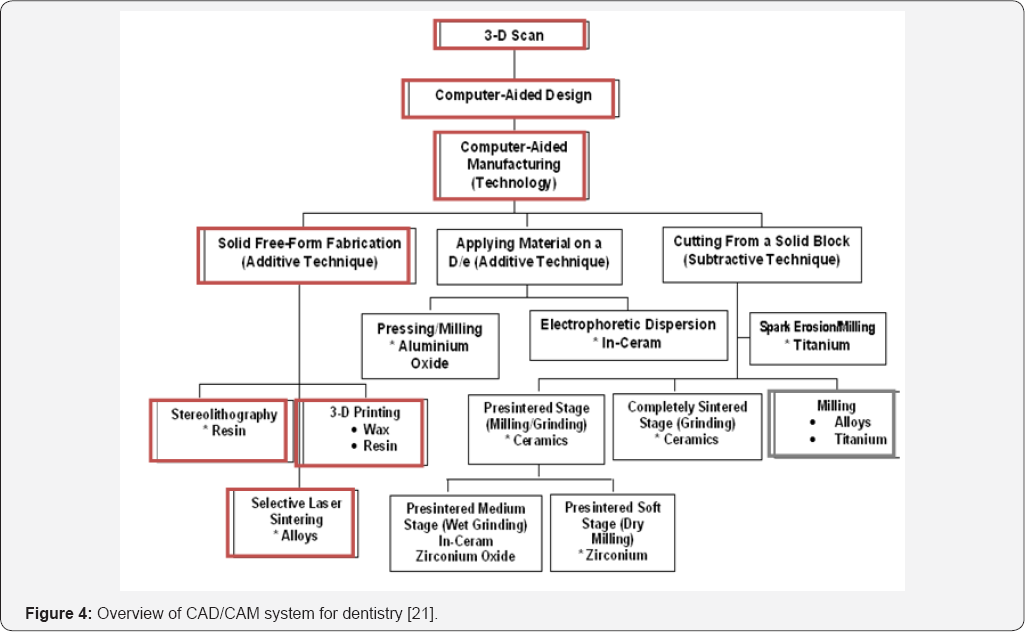
After image processing the data could be imported to CAD software, the beginning of CAD/CAM has enabled the dentists and laboratories to connect the power of computers to design and fabricate esthetic and durable prototypes. The CAD/CAM system major development started in the1980s, Duret was the first to develop dental CAD/CAM system [21]. CAD/CAM system process includes three major phases, scanning, designing and milling. The CBCT converts scan into 3D units of information (voxels) to obtain the geometrical data, and dimensions, the computer translates this information into a 3D mapping for mandible design, see Figure 4 [21]. CAD technologies have been introduced in the field of maxillofacial bone replacement to increase precision and reduce morbidity and operation time [9-11,22]. It is responsible for producing 2D or 3D part design with some conditions should be taken in consideration for the design. It also should fit the facial size, accurate, flexible, reliable, can be easily operated, handled, and be user-friendly, using the right materials should be also taken in consideration. So, CAD system doesn't cause any complications, and the final design should be easily manufactured and preferred if it have the least possible cost [1]. CAD system can provide a digital prototype for the mandible to be used for testing and evaluation so that the designers can express their opinions at early stages of the design in order to get a perfect result with fewer mistakes [9-11,22,23]. There is many CAD software, the most commonly used for the mandible reconstruction are ANSYS, ABAQUS, COMSOL, COSOMS, Solid Works, CAD software helps in finite element analysis (FEA) to obtain the properties of the mandible being designed such as mechanical, thermal, chemical, ...etc. properties. The ANSYS, ABAQUS, COMSOL, COSOMS Solid Works software packages are capable tools to use for design simulation to evaluate mechanical properties and surface characteristics of selected design before implementation.
Finite element analysis for CAD model
FEA technique is widely applied in the biomedical applications in order to understand the mechanical view point of the human body; FEA technique resolves the difficulties in measuring the stresses and strains of teeth, mandible and skull in vivo. A number of software packages for engineering analysis have been developed that are capable of covering a wide range of applications including static analysis, transient dynamic analysis, natural frequency analysis, heat transfer analysis, plastic analysis, fluid flow analysis, motion analysis, tolerance analysis [23]. The main object of the FEA method is an idealism of the object or continuum by a finite number of discrete variables [9-12]. To reach that purpose, the object is first divided into a grid of elements that forms a model of the real object, this process called meshing, each element has a simple shape such as a square, triangle, or cube or other standard shape for which the FE program has information to write the main equations in the form of a stiffness matrix. The unknown parameters for each element are the displacements at the node points, which are the points at which the elements are connected. The Program assembles the stiffness matrices for these simple elements to form the global stiffness matrix for the entire model; stiffness matrix is solved for the unidentified displacements, given the known forces and boundary conditions. From the displacement at the nodes, the stresses in each element can then be calculated. The following steps are usually followed in applying FEA [9-12,23]:
1. Discretization of the given continuum
2. Selection of the solution approximation
3. Development of element matrices and equations
4. Assembly of the element equations
5. Solution for the unknown at the nodes
6. Interpretation of the result
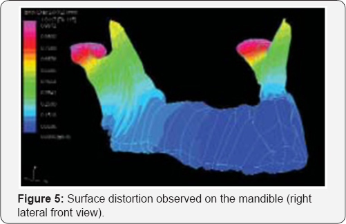
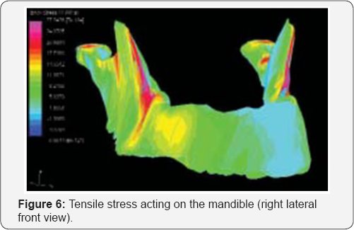
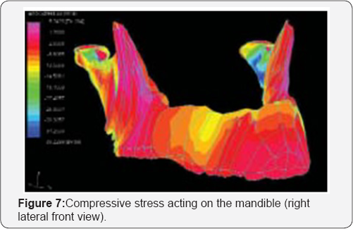
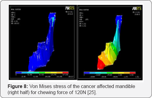
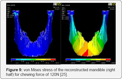
Choi et al. [24] applied commercially available FEA package STRAND7 to human mandible bone, the results was that surface distortion values were found to be in the range of 0.05-0.3mm around the premolar to the third molar regions [24]. The surface distortion of the mandible during clenching is shown in Figure 5 with the use of contour plots. Maximum surface distortions were recorded around the condylar and third molar regions.Although various clinical measurements were reported during the mandibular opening, there are no clinical distortion data available during the clenching function. The distribution of tensile and compressive stress is shown in Figure 6 & 7. Regions experiencing high magnitudes of tensile stress included the areas around the condylar region and extended to the third molar region, while high magnitudes of compressive stress were experienced in areas around the condylar region, extending to the coronoid process and also around the premolar and molar bite points Figure 8 & 9 [25].
Rapid prototyping using 3d printing technology
When design and analysis process is over, the file is exported as STL format to the 3D printer which uses plastic, metallic, biomaterials, ceramics materials and Up to 140 different Digital Materials can be realized from combining the existing primary materials in different ways in printing [26]. After printing the mandible post processing is applied to breaks away support material or dissolves it in detergent and water, sandblasting, jet-washing, grinding, infiltration, heat treatment (for metal objects), and then the part is ready to use [27]. Another important parameter such as estimation the accuracy and precession of prototype using one of coordinate metrology techniques [28,29].
Nano Biomaterials
Nanomaterials are at the leading edge of the rapidly developing field of nanotechnology [9-11]. Their unique size- dependent properties make these materials superior and indispensable in many areas of human activity. It is expected that nanotechnology will be developed at several levels: materials, devices and systems. The nano biomaterials level is the most advanced at present, both in scientific knowledge and in biomedical engineering applications [9-11]. A decade ago, nanoparticles were studied because of their size-dependent physical and chemical properties [9,30], nanotechnology is enabling technology that deals with nano-meter sized objects [9,31]. A list of some of the applications of nanomaterials to biomedical engineering is given as follows [30]:
1. Fluorescent biological labels
2. Drug and gene delivery
3. Bio detection of pathogens
4. Detection of proteins
5. Probing of DNA structure
6. Tissue engineering
7. Tumor destruction via heating (hyperthermia)
8. Separation and purification of biological molecules and cells
9. MRI contrast enhancement
Surface characteristic parameter is very important issue for implanted biomaterials metrology in biomedical engineering [32-34]. Natural bone surface contains features that are about 100nm across [5,9]. If the surface of an artificial bone implant were left smooth, the body would try to reject it, because of that smooth surface is likely to cause production of a fibrous tissue covering the surface of the implant. This layer reduces the bone-implant contact, which may result in loosening of the implant and further inflammation. It was demonstrated that by creating Nano-sized features on the surface of the hip or knee prosthesis one could reduce the chances of rejection as well as to stimulate the production of osteoblasts. The osteoblasts are the cells responsible for the growth of the bone matrix and are found on the advancing surface of the developing bone [30]. Titanium is a well-known bone repairing material widely used in orthopedics and dentistry. It has a high fracture resistance, ductility and weight to strength ratio. Unfortunately, it suffers from the lack of bioactivity, as it does not support cell adhesion and growth well. Apatite coatings are known to be bioactive and to pledge to the bone. Hence, several techniques were used in the past to produce an appetite coating on titanium, but suffer from thickness non-uniformity, poor adhesion and low mechanical strength. Though, a stable porous structure is needed to support the nutrients transport through the cell growth. An artificial hybrid biomaterial was prepared from 15-18nm ceramic nanoparticles and poly (methyl methacrylate) copolymer [30].
Result and Discussion
The purposes of this analysis were to discuss and understand CAD/CAM, FEA procedures of designing, analyzing the mandible, and how to obtain its geometrical features, dimensions and mechanical properties, coping with the CBCT image processing techniques. As with any evolving technology Cone Beam CT has some limitations and disadvantages, but it is better than conventional CT for dental radiography. Therefore, it should be essential to ensure that the radiological equipment is calibrated and has adequate contrast and sufficient brightness along with the reduced ambient lightning, so suitable monitors, ambient lightning, and equipment setting may be only available in particular offices and departments. One main disadvantage of CBCT technique it can only demonstrate limited contrast resolution, because of its high radiation scattering, the other disadvantage is that it's not efficient for soft tissue examination. Eventually, after finishing the 3D design and applying FEA using a CAD/CAM system the design is exported to the newest manufacturing technology which is 3D printing technology.
Conclusion
There are significant developments for design method have been achieved to satisfy new fabrication techniques using nano biomaterials in the field of tissue engineering. This field is very interesting with tries to reach the closest model to the original one. But the most prominent challenge is that the mechanical properties are not similar but differ for each bone structure using CBCT scan technique. CAD/CAM technology is a also very useful method to obtain the native surface morphology of the mandible into both 2D and 3D defects occur. The CAD/ CAM and FEA techniques are very important tools to design for analyses and predict both the mechanical behaviors and surface deformation of maxilla, teeth and mandible to improve and enhancing the optimal design.
References
- Abbas AT (2011) Reconstruction skeleton for the lower human jaw using CAD/CAM/CAE. Journal of King Saud University Engineering Sciences 24: 159-164.
- Macy LW. The Skeletal System.
- B(2013) Babak Jahan-Parwar, Facial Bone Anatomy.
- Jones O (2013) The Muscles of Mystification.
- Salah HR Ali (2013) Biomaterials Metrology, BME-404, Technical Report, College of Engineering Sciences. Misr University for Science and Technology (MUST).
- Luckey HA, Kubli F (1983) Titanium Alloys in Surgical Implants, STP796, American Society for Testing and Materials.
- Salah HR Ali, Marwah MAA, Abdalla SA (2013) Classifications, Surface Characterization and Standardization of Nanobiomaterials, International Journal of Engineering and Technology 2(3): 187-199.
- Salah HR, Badr SN (2015) Mechanical, tribological properties and surface characteristics of developed polymeric materials reinforced by CNTs. SAE Int J Fuels Lubr 8(1): 35-40.
- Salah HR Ali, Zahwi S, Mabrok M, Azzam B (2016) 3D-design, fabrication and metrological characteristics for knee meniscus replacement prototype using proposed polymeric material. SAE Technical Paper 2016-01-0509, doi:10.4271/2016-01-0509.
- Salah HR (2014) Developed design of humeral head replacement using 3d surface mapping, Latvian Journal of Physics and Technical Sciences.(JPTS), Physics in Engineering 51(6): 41-55.
- Salah HR Ali, Sarwat ZA Zahwi (2014) CT Measurement and Geometrical Shape Analysis for Human Shoulder Glenoid. International Review of Mechanical Engineering 8(2): 370-378.
- Mustafa Ay, Tinaz K, Cagri D, Bulent E (2013) 3D Bio-CAD modeling of human mandible and fabrication by rapid-prototyping technology. Journal of Material Sciences 2(3): 135-145.
- Feldkamp LA, Davis LC, Kress JW (1984) Practical cone-beam algorithm. J Opt Soc Am, A6, 612-619.
- Shawn A, Wenjian Z, Tom S, Paula O (2012) Cone Beam Computed Tomography for General Dentists, Open Access Scientific Reports, School of Dentistry 1(11).
- Ludlow JB, Ivanovic M (2008) Comparative dosimetry of dental CBCT devices and 64-slice CT for oral and maxillofacial radiology. Oral Surg Oral Med Oral Pathol Oral Radiol Endod 106(1): 106-114.
- Shawn A, Wenjian Z, Tom S, Paula N (2012) Cone beam computed tomography in dentistry: what dental educators and learners should know. J Dent Educ 76(11): 1437-1442.
- http://www.radiologyinfo.org/en/info.cfm?pg=dentalconect
- http://www.materialise.com/en/medical/software/mimics
- http://analyzedirect.com/
- Chitradevi B, Srimathi P (2014) An Overview on Image Processing Techniques, International Journal of Innovative Research in Computer and Communication Engineering 2(11).
- Sneha S, Abhilasha S (2010) Cad/Cam in Dental Restorations, Analysis of enhanced dentistry journal 2(3): 123-129.
- Tarsitano A, Ciocca L, Cipriani R, Scotti R, Marchetti C (2015) Mandibular Reconstruction using Fibula Free Flap Harvested using a Customized Cutting Guide: How we do it. Acta Acta Otorhinolaryngol Ital 35(3): 198-201.
- Andrew Mustun, An Introduction to Computer Aided Design (CAD), 2008-2016 by RibbonSoft, GmbH.
- Choi H, Ben-Nissan B, Conway RC (2005) Three-dimensional modelling and finite element analysis of the human mandible during clenching. Aust Dent J 50(1): 42-48.
- Ilavarasi PU, Anburajan M (2011) Design and Finite Element Analysis of Mandibular Prosthesis, 3rd Int. Conf. on Electronics Computer Technology (ICECT 2011) 3: 325-335.
- http://3dprintingindustry.com/3d-printing-basics-free-beginners- guide/history
- Andrew D, Begona M, Sauret-J, Darwood A (2015) 3D printing in dentistry, British dental journal 219(11): 521-529.
- Salah HR, M Khalafalla I, Naeimand S (2016) Experimental and theoretical validation method for estimation of straightness deviation and associated uncertainty in CNC-CMM measurement. International Journal of Smart Sensing and Intelligent Systems 9(2): 397-418.
- Salah HR (2014) Performance Investigation of CMM Measurement Quality using Flick Standard. Journal of Quality and Reliability Eng 2014(2014): 11.
- Salata OV (2004) Applications of nanoparticles in biology and medicine. J Nanobiotechnology 2(1): 3.
- (2015) Industrial, Medical and Environmental Applications of Microorganisms. Wageningen Academic Publishers, Netherlands.
- Salah HR, Marwah MA, Abdalla SA (2013) Recent progress in nanometrology techniques for object characterization. International Journal of Engineering Research and Applications 3(4): 1343-1366.
- Salah HR Ali (2012) Advanced nano measuring techniques for surface characterization, ISRN Optics Journal 2012(2012): 1-23.
- 34. Shuwen Z, Dominique B, Ho-Pui H, Ken T (2014) Nanomaterials enhanced surface plasmon resonance for biological and chemical sensing applications. Chem Soc Rev 43(10): 3426-3452.


