


Encapsulation of Problems Associated with Maintenance of Federal Universities Hostel Buildings in Southeast Nigeria
Jakub Šejna* and František Wald
Department of Civil Engineering, Czech Technical University in Prague, Prague, Czech Republic
Submission: October 14, 2021; Published: October 25, 2021
*Corresponding Author: Jakub Šejna, Department of Civil Engineering, Czech Technical University in Prague, Prague, Czech Republic Civil Eng
How to cite this article:Šejna J, Wald F. Small Furnace Experiments for Wood Burning Pyrolysis Models. Civil Eng Res J. 2021; 12(3): 555838. DOI 10.19080/CERJ.2021.12.555838
Abstract
This article presents a study focused on the fire resistance of steel structures when solid wood cladding or OSB panels are used. The measured properties of wood at elevated temperatures are presented. Wood pyrolysis is studied with the use of available procedures for calculating the influence of pyrolysis on fire development. The development of the charred layer is studied as a desirable part that fills the insulating layer. When this effect is shown in the experiments, the charred layer slows down the heat transfer to the structure. The charred layer will last on the steel member throughout the investigation or will fall off and expose the steel member to more rapid heating. The paper presents insights identified in previous research. Our study presents the basic possibilities of access to the wood pyrolysis model. Finally, experiments in a small-scale furnace investigating the influence of pyrolysis on the development of temperatures in the test furnace and the development of the charred layer with its influence on the insulation properties are presented.
Keywords: Wood pyrolysis; Charred layer; Fire resistance; Steel structures; Cladding; OSB panels
Introduction
Fire resistance is one of the most critical areas in the design of members and entire structures of buildings to ensure the resilience of the components or system when it is exposed to the effects of fire, and to ensure rapid and safe evacuation of people in the building. Protecting the immediate vicinity of the building is also an integral aspect of the fire resistance of a structure, i.e., preventing the fire spreading to surrounding buildings. When designing wood or steel members, the limits of the materials are often underestimated to the point that, without the application of fire protection or oversizing of individual parts, members or whole structures fail very early, e.g., within 7 mins. When designing wooden structures, it is necessary to take into account wood flammability and the influence of flammability on the development of the fire, e.g., a faster increase in temperature, higher temperatures in a given compartment. The design of a structure should include the formation of a char layer and the development of a layer of pyrolysis. The standards indicate the basic procedures for the design according to empirical formulae or, for example, according to the non-linear methods presented in the Wood Handbook [1]. Steel structures that have to withstand fire for more than 15 min have to be protected from high temperatures. A foam coating, an insulation layer spray, or gypsum board material is used for fire protection. In practical applications, gypsum board is the most widely-used material. Another option is to use wood or OSB as a protective cladding for the steel member. The challenge is that the added material is flammable. The main question is therefore how best to protect a steel structure from the effects of fire by using wood or wood-based materials in such a way that the structure continues to be classified as non-combustible. An option for laying the groundwork for an amendment to the legislation is to look at modelling and experimenting with protective steel structures. A major challenge in modelling wood burning or any wood thermal stresses is how to present correctly the thermal degradation of the material and the influence of pyrolysis, which will influence the development of a fire in a compartment. Numerical simulation or an advanced analytical calculation may be used to analyse the position of the charring line in detail. The speed of wood burning depends on many factors, in particular the intensity of the temperature load, the density and the humidity of the wood, the emissivity of the material surface, the direction of fire spread over the members (horizontal, vertical), etc. For reliable results, however, appropriate input data must be applied. Examples include the heat needed to evaporate dry wood, the precise coefficient of emissivity of the material surface, the surface temperature of the member as a function of temperature, load variation, the average temperature of pyrolysis, etc. The calculation is very complex, in particular due to the specific input data that are required.
Material properties of wood
Thermal conductivity
Thermal conductivity is affected by the diminishing humidity of the wood and by the formation of a layer of charring. There are two ways to accommodate the change in thermal conductivity. The first step is to change the thermal conductivity as the temperature rises. This procedure was established by Knudson and Schneiwind [2] as early as 1975, and because of its universality the procedure has subsequently been adopted by many other publications and standards. In 1999, König et al. [3] found that the thermal conductivity reached much more pronounced values when temperatures reached above 500 °C. The temperature conductivity pattern of Knudson et al. was therefore adjusted. Findings on the course of changes in thermal conductivity are always directly dependent on the type of wood and the location where it was harvested. The generalization of individual thermal conductivity development is therefore always approached with the assumption of thermal conductivity at an average temperature. Assuming the use of non-spruce wood with unknown thermal characteristics, where the detailed course is not known, a conversion employing a temperature-dependent reduction ratio is used. This is a simplified form, which approximates earlier experiments and can serve for a basic estimate of the properties of the material. The relationship between isotropic thermal conductivity and temperature is given in EN 1995-1-2:2005 [4], where wood unification is assumed. Temperature deformation may be considered in conjunction with the specific heat capacity, depending only on the loss of moisture in the wood or on a slight increase in the body due to the development of water vapor, which has a larger volume than the original water. These findings are transposed to the model as a temperature-dependent property of the members being studied. It is not dependent on force action and does not primarily trigger cracks in the body. The development of temperature deformation to 300 °C is no longer taken into consideration, due to the assumption that all the water vapor has already evaporated from the body. (Figure 1) clearly shows the increasing heat capacity, because heat is needed to start wood pyrolysis.

Density
The most significant changes in volume density occur at around 220-320 °C, when, due to thermal degradation and burning of wood, the raw wood is converted into a charred layer. The wood burns in this temperature range. However, the burning process is not yet limited by a charred layer, which would act as insulation and protection for the lower layers of the wood. At higher temperatures, the density decreases more slowly. Another break occurs at 800 °C, when the charred layer has been wholly transformed into ash. For illustrative purposes, when comparing the density at room temperature and at 400 °C, the density loss due to the release of volatile substances and due to the development of charred layer is about 40 %. Thus, wood at 300 °C has 60 % of the density of the raw wood.
Specific thermal capacity
In particular, the humidity contained in the wood is a fundamental factor in influencing the change in the specific heat capacity. At initial temperatures, i.e., up to 200 °C, the course of the specific heat capacity is related to the evaporation of moisture and its conversion into water vapor, which in turn makes its way through the wood to the surface. When the free moisture in the material evaporates, the density of the wood decreases due to the thermal degradation of the wood, i.e., due to the course of pyrolysis. An essential representation of the course of the specific heat capacity is given in EN 1995-1-2, where a large increase in thermal capacity is shown at 100 °C. At this point, much energy is consumed to convert moisture into water vapor. Similar behaviour is observed for concrete exposed to fire, where the water bound in the concrete is also converted into water vapor (Figure 2).

Wood Pyrolysis
Pyrolysis is the thermal decomposition of organic matter in an inert atmosphere. In the first stage of pyrolysis an endothermic reaction occurs, in which energy is consumed up to the initial temperature of the wood [5]. Constant chemical reactions are assumed, and a specific amount of flammable gases released into the environment and released by the heat source can also be assumed. The chemistry of pyrolysis is influenced by the composition of the wood, with the proportion of volatile substances contained in the wood reaching up to 77 % of the weight of dry wood (Table 1) [6]. For simplicity, the overall mechanism of pyrolysis is divided into primary and secondary responses or can only be calculated with a single-reaction scheme. The primary reaction concerns wood construction units, from a modelling perspective, it is necessary to introduce fictional components that can be identified as lignin, cellulose, and hemicellulose components, where pyrolysis of individual substances occurs simultaneously. For the correct choice of pyrolysis model, it is always necessary to choose the pyrolysis sleeping mechanism according to the data entered. Below you can note the different patterns from Rinta-Paavola [7] or Ira [8]. In the case of mechanical reasoning with two reactions, it can be assumed that the primary reaction is affected only by local temperature. The secondary reaction involves the decomposition of the resulting substances from the primary reaction, thereby affecting the further development of the charred layer due to the combustion of volatile substances [9].
The individual reaction components are described by a first-order differential equation, where the mass fraction at the beginning is equal to 1.0, then during pyrolysis it changes to form a charred residue. The calculation is solved by the Runge-Kutty method in time to determine the residual mass fraction for each wooden component [9,10].
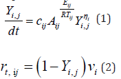
Subsequently, the effect of temperature changes caused by pyrolysis is calculated with the coefficients of pyrolysis using the equation of the mass rate of burning. The temperature increase depends on the wood initiation temperature and the surface temperature of the examined element.
The calculated values can be used to calculate the rate of heat release to the surroundings by pyrolysis using the effective calorific value of the wood and the original weight of the woodbased element or element.
When determining the mass burning rate, wood should
be divided into fictitious building blocks, namely the cellulose
component, the hemicellulose component, and the lignin component. However, it can be solved with one fictitious
component of wood. It always depends on the chosen scheme of
the pyrolysis mechanism. For each type of wood, the distribution
is noticeably different. Each wood has different reaction factors,
which should always be considered. The response rates  n and
n and  should be drawn from expert articles [6-8]. Account should be
taken of the error of the difference in the construction of wood
and samples from other parts of the tree. Pyrolysis is measured
as a complex problem, with homogenization of the sample by
default. For illustration, the temperature development in the DTA
analysis is shown in (Figure 3) when a scheme is compared with
one fictitious component or up to three. Below is a scheme of
pyrolysis for experiments presented at this article.
should be drawn from expert articles [6-8]. Account should be
taken of the error of the difference in the construction of wood
and samples from other parts of the tree. Pyrolysis is measured
as a complex problem, with homogenization of the sample by
default. For illustration, the temperature development in the DTA
analysis is shown in (Figure 3) when a scheme is compared with
one fictitious component or up to three. Below is a scheme of
pyrolysis for experiments presented at this article.


The pyrolysis reaction schemes by Rinta-Paavola [7]:
reaction 1: extractivies → chare + volatiles
reaction 2: hemicellulose → charhc + volatiles
reaction 3: cellulose → charc + volatiles
reaction 4: lignin → charl + volatiles
The pyrolysis reaction schemes by Ira [8]:
reaction 1: extractivies → chare + volatiles
reaction 2: hemicellulose → charhc + volatiles
reaction 3: cellulose → charc + volatiles
reaction 4: lignin → charl + volatiles
Options for implementing pyrolysis into models
The easiest way to include the influence of pyrolysis in smallscale models is to combine the burner power with the released energy of wood pyrolysis. The power added to the fire site is calculated on the basis of the mass rate of decanting obtained by the cost coefficients. A cyclic calculation is still needed in order to include the effect of the increase in the furnace temperature and thus the faster course of the pyrolysis. Let us suppose that computational programs are used that allow pyrolysis to be calculated concurrently with the simulation (program FDS - Fire Dynamics Simulator). In that case, it is appropriate to use these procedures to verify the contribution of the influence of pyrolysis to the secondary calculation. This predicted process is possible with small wooden samples. Ideally, this solution is offered when there is a need for an initial prediction of the behaviour of the oven temperature or to ascertain the contribution of pyrolysis to the evolution of the temperature in the furnace.
In this procedure, the effect of a wooden element slowing the passage of the released water vapour is not taken into consideration in the calculation, for the following reasons:
a. The element is so small/thin that the influence of water vapour does not manifest
b. The simplified model fails to consider vapour evaporation options
c. Due to the simplicity of the calculation, the effect of the added released energy takes time to manifest, and the assumption is accepted that the deceleration due to the calculation will include the effect of the released steam
Charred Layer as an Insulator
Thermal degradation and burning transforms wood into a charred layer with physical-mechanical properties different from those of the raw wood. The main significant change is the insulation property, the change in thermal conductivity, in (Figure 4), which increases significantly and prevents further degradation of the wood member. The charred layer has little or no resistance to force action, with only crude non-degraded wood transferring the load. It is therefore necessary to define as precisely as possible the depth of the wood charring, which reduces the original cross-section to effective dimensions. The conversion to an efficient cross-section that is considered for the transmission of stresses ensures safe design of the structural members. The formation of a charring layer is taken into consideration for all wood surfaces which are exposed to fire and are not protected [4]. First of all, it is important to note that wood carbon monoxide occurs in the protected member and the charring rate is reduced.

The temperature distribution is taken into consideration. The temperature under the charred layer of 288-300 °C is determined by the carbonation depth, using the isotherm 300 °C method. Due to its distinctive insulating properties, the temperature of the charred layer is reduced to 180 °C by a layer 6-7 mm in depth [1]. In the case of wood-burning models, when even the calculation involves the comprehensive removal of a part of the sample, the multiphysical problem needs to be addressed. This issue was discussed by Šulc et al. [11], in their description of the basic approaches to model building using OOFEM (program). Part 5 of this article compares the linear charring rate according to the results of experiments with the FEM model reflecting the results of the experiments.
FDS and FEM Models
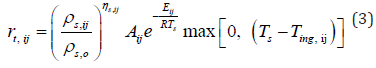
For the purposes of determining the temperatures in the smallscale furnace and the early stages of the influence of the flammable gases released by pyrolysis of the samples, temperature patterns have been determined using the FDS program, after the exact geometry of the small-scale test furnace has been modelled (for the dimensions, see section 6). The simulation verifies the burner settings for maintaining temperatures up to 800 °C, which is the temperature that is important for maintaining wood density of at least 20 % of the original value. Two simulations, MF.1 and MF2, were performed. In the MF.1 simulation, the burner power was set according to ISO 834, reaching a temperature of 900 °C (Figure 5). In the MF.2 simulation, the effect of spruce wood pyrolysis was considered with the Rinta-Paavola kinetic coefficients of pyrolysis [12]. The kinetic coefficients of pyrolysis are shown in (Table 2). For simulation MF.3 with OSB cladding, values of the kinetic coefficients of pyrolysis from Ira et al. were used [13] and are shown in (Table 3).


When the influence of pyrolysis (MF.1) was included, 150 °C higher temperatures were reached, on average, than in the first model, in which pyrolysis is not taken into consideration (MF.2). The MF.1 and MF.2 simulation runs are shown in (Figure 6). On the basis of this finding, a course of experiments in a small-scale furnace with burner settings up to 800 °C was established to take into consideration the charred layer forming the protective layer in at least 20 % of the raw wood density.
The total amount of wood in the MF.2 simulation was considered per sample, based on the samples produced for the experiments. There was 150 g of spruce wood in a 20 mm layer, i.e., 600 g was modelled at the ceiling level of the smallscale furnace. The final setting of the burner power reflects the influence of pyrolysis of spruce wood used as a cladding for steel sheets. The effect of adjusting the burner power for the influence of pyrolysis and reaching the maximum temperature is shown in (Figure 1). The reduction in the burner power was set at the beginning of the influence of component cellulose pyrolysis and at the second decrease (or holding a constant level) in the pyrolysis of components hemicellulose with lignin. A comparison between the model results and the experiment showed that identical values were achieved.
Using FEM models, the CFD models were validated. The calculated values were compared with the steel sheet temperatures measured in the experiments for spruce wood panelling and OSB. Material characteristics were used according to EN 1995-1-2 and EN 1993-1-2. Differences in the resulting models were based on a sensitivity analysis of FEM models at 5 °C and 10 °C, respectively, in the early stages of wood water release. Based on the validated FEM models, the charring depths were subtracted on the basis of time compared to the linear rate of wood cladding flaring. The comparison assumes that the insulation layer effect occurs at charring of about 15 mm and then slows down the charring rate (Figure 7). In the case of OSB panelling, the same results are obtained, i.e., there is a decrease in the charring speed after the removal of 15 mm (Figure 8).


Experiments
To validate the models described in Chapter 5, experiments were conducted in a small-scale furnace at UCEEB CTU. Two steel sheet protection experiments were chosen: protection by a lining 20 mm in thickness, and protection by an OBS plate 22 mm in thickness. These thicknesses were selected according to the linear rate of development of the charcoal layer, providing protection for about 20 min, i.e., experiments with a heating time of 30 mins could be carried out, and the influence of wood pyrolysis and OSB, the development of the charred layer and its insulating properties could be observed for the first 20 mins (Figure 3). The 1200 × 830 × 830 mm small-scale furnace consists of a steel frame structure with fire protection panels; the intake and extraction holes are located on the longer wall of the furnace. A burner measuring 300 × 100 × 100 mm, allowing maximum power of up to 300 kW, was used in the small-scale furnace. The complete geometry of the furnace is shown in (Figure 9). For the small-scale test, 4 samples were placed in the test furnace at each time so that possible variations in the heating pattern of the furnace could be observed. The samples were made of a 12 mm thick steel sheet, measuring 180 × 100 mm. The steel sheet was designed to simulate the lower band of the steel profile. This would protect the steel sheet from the underside with a spruce wood poultice (variant of experiment No. 1) 20 mm in thickness and an OSB slab poultice 22 mm in thickness (experiment variant No. 2). These materials were used to reflect the wood or wood-based materials that are most widely used in Central Europe (Figure 10 and Figure 11).


The grain plates were glued to the steel plate using a stove putty resisting temperatures of up to 1200 °C. This approach was chosen because if the wood had been heated to 1200 °C, the adhesive would have failed, and the layer would have fallen off, (Figure 12). For experiment No. 2, one sample simulated the falling off of the charred layer. This made it possible to monitor the temperature evolution in a suddenly unprotected steel sheet. The warm-up time of the samples in the small-scale furnace was set at 30 min and 15 min of sample cooling, after which the temperatures of the steel samples were monitored for subsequent validation of the models. The measured temperature progression values in the test furnace and on the protected steel sheet are shown in (Figure 13) and (Figure 14), when OSB sample #3 was simulated with the release of the protective layer, after the layer had been completely removed. The subsequent rapid increase in the 0160 steel sheet temperature is linked to the material characteristics of the steel sheet. In the case of OSB sample #2, the partial debris of the charred layer (10 mm in thickness) has been symbolized, and the resulting increase in temperature is more gradual due to the stilloccurring charred layer and its insulating properties.


Conclusion
This article has presented a proposal for integrating pyrolysis into simulations of the influence of pyrolysis on small-scale tests of wood cladding on a steel sheet. It has been established that the burner power setting must be reduced to prevent temperatures above 800 °C.
a. The effect of pyrolysis in a small-scale test on spruce wood panelling and OSB is to increase the temperature in the furnace by up to 250 °C
b. The surface temperature of the cladding, and therefore the temperature in the test furnace, must not exceed 800 °C. At this temperature the charred layer falls off and the test is stopped.
c. The fire resistance of a wood cladding with a steel sheet 20 mm in thickness can increase the fire resistance by up to 20 min, and with a thickness of 22 mm for OSB the fire resistance is increased by up to 21 min.
d. After a 15 mm charred layer is formed, the rate of charring of the wood cladding slows down
e. For a tile of spruce wood 20 mm in thickness or OSB 22 mm in thickness, the temperature of the steel members after 30 mins of testing did not exceed 200 °C. In the event of a breach or fall of the protective layer, the steel sheet temperatures rise sharply.
Based on the findings presented in this article, it will be possible to address the impact of the use of wooden materials to protect steel members. Knowledge is used to prepare wood claddings tests for the rate of charring, and to eliminate the influence of the adhesive used for joining the protective plate and the steel sheet in the Room corner test and a small-scale furnace.
Acknowledgement
The work presented here was carried out within the framework of GACR project No. 19-22435S Behaviour of Structures with Wooden Fire Protection – multi-physical modelling.
References
- Ross Robert (2010) Wood handbook: wood as an engineering material. USDA Forest Service, Forest Products Laboratory, General Technical Report FPL-GTR-190.
- Knudson, RM, AP Schniewind (1975) Performance of structural wood members exposed to fire. Forest Prod J, USA.
- König, Jürgen (2006) Effective thermal actions and thermal properties of timber members in natural fires. Fire and Materials: An International Journal.
- EN 1995-1-2 (2004) (English): Eurocode 5: Design of timber structures.
- Reinprecht, Ladislav (2016) Wood deterioration, protection, and maintenance. John Wiley & Sons.
- Sinha SA, Jhalani MR, Ravi A Ray (2000) Modelling of Pyrolysis in Wood: A Review. SESI Journal 10(1): 41-62.
- Rinta‐Paavola Aleksi, Simo H (2022) A model for the pyrolysis of two Nordic structural timbers. Fire and Materials 46(1): 55-68.
- Ira J, Hasalová L, Šálek V, Jahoda M, Vystrčil V (2020) Thermal Analysis and Cone Calorimeter Study of Engineered Wood with an Emphasis on Fire Modelling. Fire Technology 56(3): 1099-1132.
- Sinha S (2000) Modelling of pyrolysis in wood: a review. SESI Journal.
- Wade Colleen (2019) Enclosure fire model for mass timber construction–benchmarking with a kinetic wood pyrolysis sub model. Interflam: 15th International Conference on Fire Safety Engineering.
- Šulc, Stanislav, Šmilauer V, František Wald (2021) Thermal Model for Timber Fire Exposure with Moving Boundary. Materials 14(3): 1-10.
- Rinta‐Paavola A, S Hostikka (2021) A model for the pyrolysis of two Nordic structural timbers. Fire and Materials.
- Ira Jiří (2020) Thermal analysis and cone calorimeter study of engineered wood with an emphasis on fire modelling. Fire Technology.


