Elastic Critical Stress for Trapezoidal Sheeting with Flange and Web Stiffeners
Torsten Höglund*
Department of Civil and Architectural Engineering, Steel Structures, Royal Institute of Technology, Sweden
Submission: January 10, 2020; Published: February 03, 2020
*Corresponding Author:Torsten Höglund, Department of Civil and Architectural Engineering, Royal Institute of Technology, KTH Stockholm, Sweden
How to cite this article: Torsten Höglund.Elastic Critical Stress for Trapezoidal Sheeting with Flange and Web Stiffeners. Civil Eng Res J. 2020; 9(5): 555772. DOI: 10.19080/CERJ.2020.09.555772
Abstract
In Höglund, T. “Design of trapezoidal sheeting provided with stiffeners in the flanges and webs”. Swedish Council for Building Research Document D28:1980 [1], the formulae for the design of trapezoidal sheeting with flange and web stiffeners are derived. In Eurocode 3, Part 1-3 only the simplified conservative formula is used as the background formulae are supposed to be too complicated in a code. However, they better agree with tests and are therefore given here.
Keywords: Trapezoidal sheeting; Stiffeners in flanges and webs; steel; Aluminium; Bending moment;
Elastic Critical Stress
In Eurocode 3, Part 1-3 [2] and Eurocode 9, Part 1-4 [3], the modified elastic critical stress for sheeting with flange stiffeners and web stiffeners is given by the formula
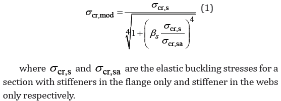
As an alternative to the expression (1) the expressions in [1] gives better agreement with the tests
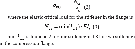
and 11k is found in 2 for one stiffener and 3 for two stiffeners in the compression flange.
One Stiffener in the Compression Flange
Calculate the buckling coefficient 11k for different buckling length l using

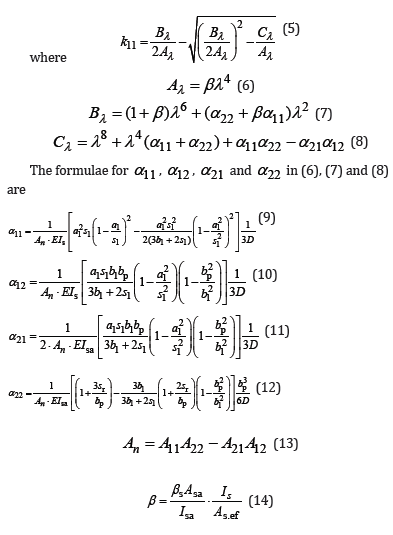
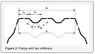
in which the notations for dimensions of flange and web parts are found in Figure 1 and s β is according to [1] and the Eurocodes [2] and [3]


Further notations are

Asa is the effective cross-section area of the intermediate web stiffener
Is is the second moment of inertia of the intermediate flange stiffener, see 5.5.3.4.3 in [2]
Isa is the second moment of inertia of the intermediate web stiffener, see 5.5.3.4.3 in [2]
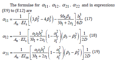
The difference between the above formulae and the formulae in [1] is that the above formulae take the width of the stiffeners into account in transverse bending of the flange and webs.
Two Stiffeners in the Compression Flange

Examples
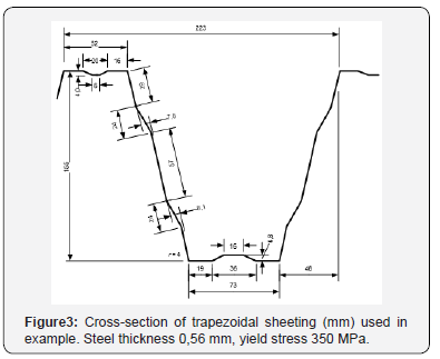
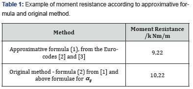
The trapezoidal sheeting with dimensions as in Figure 3 is calculated with the two methods which gives the result according to Table 1. In this example the web stiffeners are wide which means that the force in the stiffeners is large compared to the stiffness of the stiffener. Therefore, the increase of the resistance due to web stiffener is relatively small. For a cross section where the web stiffeners have smaller width-to-height ratio (Figure 4) the influence of the web stiffener is relatively larger.
Conclusion
The original formulae for the distortional buckling stress of the stiffeners of trapezoidal sheeting are improved so that the influence of transverse bending of the stiffeners are considered. The buckling stress and the resistance is increased considerable if these formulae are used instead of the approximative formula in the Eurocodes for steel and aluminium.

Acknowledgement
Department of Civil and Architectural Engineering, Royal Institute of Technology, KTH Stockholm.
References
- Höglund T (1980) Design of trapezoidal sheeting provided with stiffeners in the flanges and webs. Swedish Council for Building Research p. 82.
- EN 1993-1-3 Eurocode 3: Design of steel structures - Part 1-3: General rules - Supplementary rules for cold-formed members and sheeting.
- EN 1999-1-4 Eurocode 3: Design of aluminium - Part 1-4: Cold-formed structural sheeting.


