Identifying the Trouble Zone Above Buried Conduits and Stress Reduction Using Compressible Inclusion
Ahmad AbdulHaleem Mohammed1*, Ahmad El-Raji2 and Sharif ElKholy2
1College of Engineering and IT, Qassim University, Saudi Arabia
2Qassim Engineering College, Qassim University, Saudi Arabia
Submission: April 13, 2019; Published: April 24, 2019
*Corresponding Author: Ahmad AbdulHaleem Mohammed, College of Engineering and IT, Onaizah Colleges, Qassim University, Saudi Arabia
How to cite this article: Ahmad AbdulHaleem Md, Ahmad El-Raji, Sharif E. Identifying the Trouble Zone Above Buried Conduits and Stress Reduction Using Compressible Inclusion. Civil Eng Res J. 2019; 8(1): 555730.DOI: 10.19080/CERJ.2019.08.555730
Abstract
In the recent years, the Kingdom of Saudi Arabia started some huge projects in the field of infrastructure development through all the Kingdom regions. Reinforced concrete pipes are considered to be a good and economic choice for sewage pipes because they are less expensive, locally produced, and environmentally safe. The use of reinforced concrete pipes is not limited to the sewage systems, but they are also used in water and oil transfer as well as in storm water drainage systems and utility tunnels throughout the Kingdom cities.
The current paper aims to identify the trouble zone above buried conduits to be careful during installation pipes or construct buildings on these zones and to investigate how to improve the performance of rigid conduits under heavy overburden soil loads using EPS-Polystyrene around it and compared the geometry of trouble zone above pipe with different diameters of pipes and modulus of elasticity of inclusion. The results of the study show the improvement in the performance of reinforced concrete pipes under high overburden pressure by reducing the vertical stress above buried pipes around 95% when using a thin layer of EPS-geofoam around pipes due to the development of arch action above the pipe. Furthermore, the trouble zone determined for different diameters of pipes to protect buildings that will constructed from settlement.
Keywords: Buried pipes; Stress reduction; EPS geofoam; Disturbance zone; FLAC; Reinforced concrete
Introduction
In the recent years, engineers started to use new materials for the sewage pipes such as plastic, reinforced concrete, and fiberglass. Reinforced concrete (RC) pipes are considered an economic and environmentally safe alternative when engineers think of installing utility pipe lines for sewage and water projects. Compared wither other types such as steel, composite, or plastic pipes, concrete pipes are built using locally produced, less expensive, and less harmful to environment materials. The serious problem that threatens the increase the usage of concrete pipes is their ability to resist high overburden pressure when burying them at high embedment depth underground surface and their effects on constructed buildings.
There are two types of pipes can be used for transfer fluids under the ground surface, rigid and flexible pipe. Rigid pipes are generally limited by thrust in the pipe wall and cracking in the pipe like reinforced concrete, plain concrete and clay pipes. Flexible pipes are generally limited by deflection, buckling, and yielding in the pipe wall like metal and plastic pipes [1].
EPS is the abbreviation for Expanded Poly Styrene. Expanded polystyrene, EPS-Geofoam is a lightweight material that has been used in engineering applications around the world since at least the 1950s [2]. (EPS) geofoam is an ultra-light material that used in transportation infrastructure projects to reduce vertical and horizontal stresses subjected to buried pipeline and culvert systems [3]. It is a lightweight cellular plastic material consisting of fine spherical shaped particles which are comprised of 98% air [4]. EPS geofoam is manufactured by pre-expanding polystyrene beads which are molded and fused in block-molds using dry saturated steam [5].
During the period from 1988 to 1992 researchers measure the deformation and the vertical and horizontal earth pressure on buried concrete pipes using hydraulic pressure cells. Hydraulic earth pressure measuring cells can installed next to pipe in both sides and above pipe below and above compressible layer with measured distance [6]. For installations with granular backfill material, the long-term measured vertical pressure above the pipe ranged from 23% to 25% of the overburden pressure and about 45% for the one with cohesive soil backfill. Also, the type of soil used in the embankment construction affect the performance of induced arching because the field with granular fill reduced the vertical pressure over the culvert more than the one with silty-clay embankment. The results also show that the deformation of EPS compressible layer is greater in cohesive fill than in granular fill.
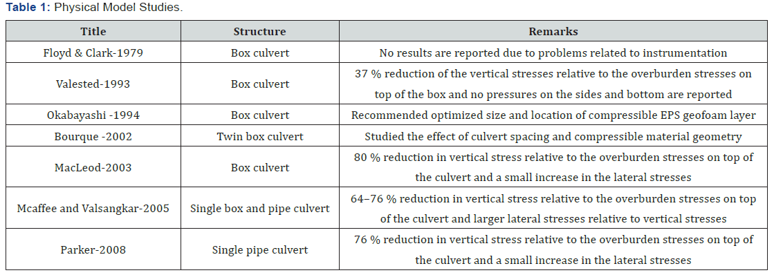
The final compression of the EPS geofoam compressible layer at the end of embankment construction ranged from 27 % to 32 % for concrete pipes with granular fill and 50 % for cast-in-situ box culvert with cohesive fill. So, the induced trench installation method is successful in reducing the vertical loads on the buried pipes and culverts and it depends on the selection of backfill material with higher stiffness like granular fill material [6]. Table 1 shows a list of physical model studies on induced trench for different researchers from 1979 to 2008 [7].
Objectives
This research aims to achieve the following objectives:
1- Identifying the geometry of disturbance zone above buried pipes with different diameters of pipes surrounded with inclusion that graded from flexible to rigid materials.
1- Identifying the geometry of disturbance zone above buried pipes with different diameters of pipes surrounded with inclusion that graded from flexible to rigid materials.
Methodology
In this research the study of a problem will made by a numerical model using FLAC 8.0 (finite difference analysis software). FLAC is a two-dimensional explicit finite difference program used for engineering mechanics computation [8]. This program used for engineering problems to simulates the behavior of structures built of soil, rock, concrete or other materials [8]. FLAC also contains many special features like interface elements, plane stress, plane strain, groundwater and consolidation and structural element models. It also contains a database for materials and its properties that will use in a model. Analytical verification for numerical results done using equations to calculate a vertical stress above buried pipe.
Numerical model
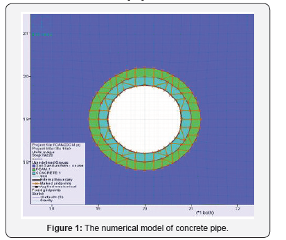
The numerical analysis done by using FLAC finite difference analysis program. Models and simulation are done for a concrete pipe under the ground surface 20m deep that surrounded with 20cm thickness of cover material (Figure1) that tested with different modulus of elasticity from flexible to rigid material.
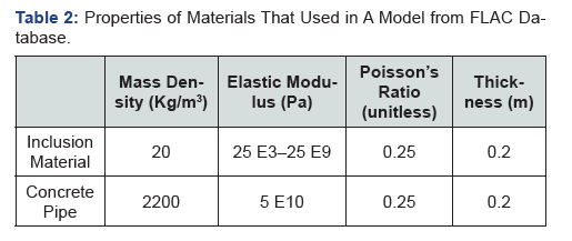
This test show how the stress on pipe will reduce by distribute the loads around pipe with arch action method because there is an incompressible layer around it. Also, from strain border above pipe the disturbance zone geometry can be determined. Dimensions used in this simulation are 40m X 40m and its divided into grids with 200 X 200 elements which that each element is 20cm X 20cm. Tables 2&3 shows the properties of materials from database of FLAC that used to prepare a model.
Loading and boundary conditions: This model ran with a dead load of backfill soil without adding any external loads with the following boundary conditions:
a. Fix X axis at i = 1 and i = 201.
b. Fix Y axis at j = 1.

Results and Discussion
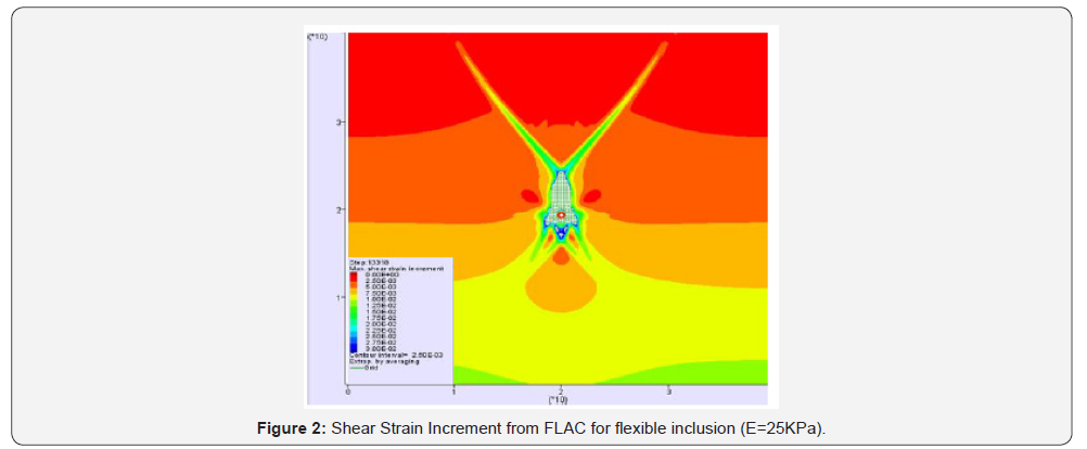
Figure 2 from FLAC software shows the shear strain increment that indicates the disturbance zone above buried pipe and show the top and bottom width of this zone by colouring the strain line and its geometry near the shape cone. Shear strain: it is defined as the ratio of the change in deformation to its original length perpendicular to the axes of the member due to shear stress of soil. It is dependent on shear stress and shear modulus.
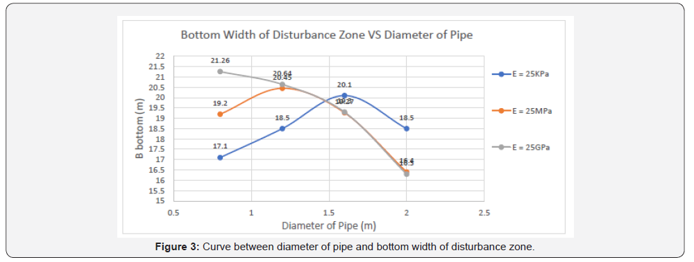
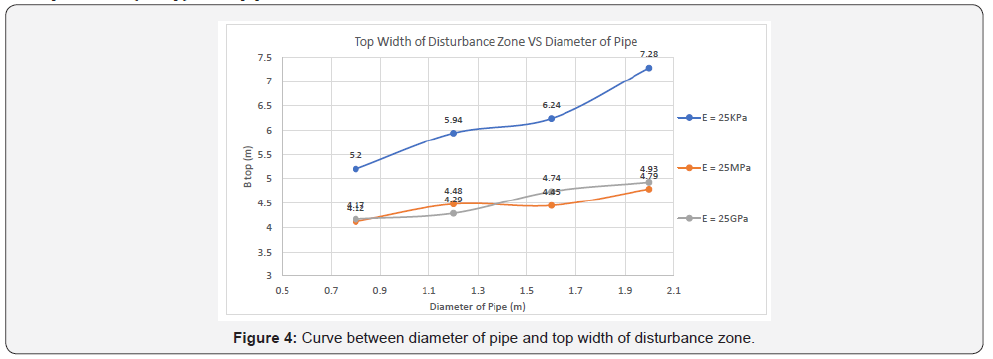
Simulation done 12 times with a model showed in Figure 1 for different diameters of concrete pipes with ranged modulus of elasticity of cover material from 25KPa to 25GPa. Figure 3 shows the curve between diameter of pipe and the bottom width of disturbance zone directly above pipe for each modulus of elasticity of inclusion material. We can notice that the bottom width directly proportional to the diameter of pipe in the case of flexible pipe and inversely proportional in the case of rigid pipe. Figure 4 shows the curve between diameter of pipe and the top width of disturbance zone above pipe near the surface of ground for each modulus of elasticity of inclusion material. We can notice that the top width directly proportional to the diameter of pipe in the case of flexible and rigid pipe.
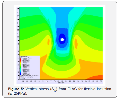
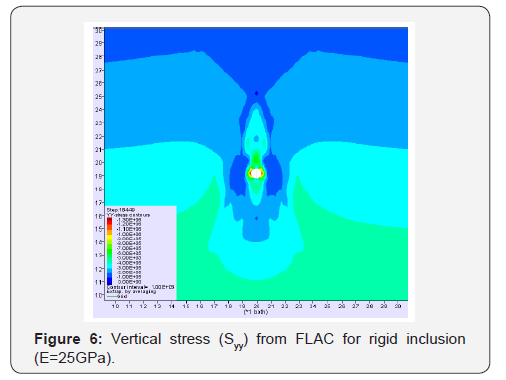
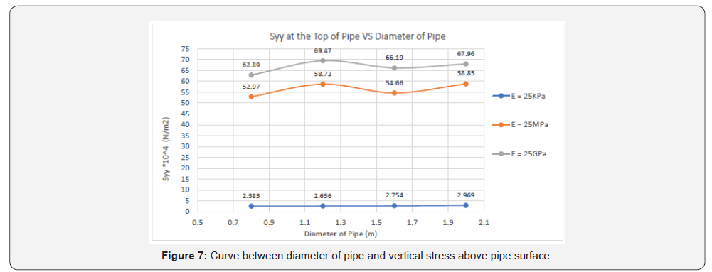
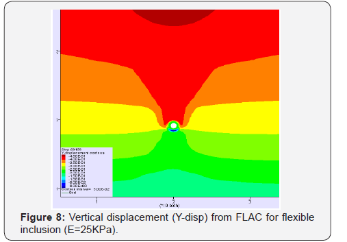
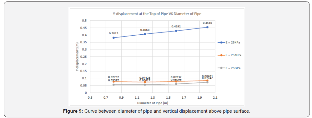
Figures 5&6 from FLAC simulation show the difference in values of vertical stress between flexible and rigid inclusion around pipe and how the flexible inclusion reduces the stress around 95%. Figure 7 shows the curve between diameter of pipe and the vertical stress (Syy) above pipe near the surface of inclusion material for each modulus of elasticity. We can notice that the vertical stress above flexible material reduced about 95% from rigid material. Figures 8&9 show the vertical displacement of simulation from FLAC and the curve between diameter of pipe and the vertical displacement (Y-disp) above pipe near the surface of inclusion material for each modulus of elasticity. We can notice from curve that the flexible material causes more vertical displacement than rigid material. Figure 10 shows a vertical section for a geometry of disturbance zone above concrete buried pipe surrounded with inclusion.
Analytical Verification of a Numerical Results
This verification done for all models that have modulus of elasticity for inclusion material same as soil modulus E = 25MPa using prism load equation for trench method [9].
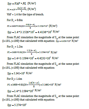

From FLAC simulation the magnitude of Syy at the same point (i=101, j=100) that calculated with equation:
Syy = 5.881.8105 N/m2
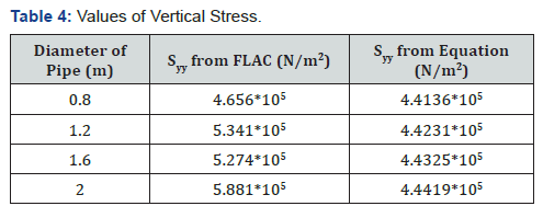
Table 4 shows the values of vertical stress for all models that get from FLAC software and from equation.
Conclusion
Model studies of circular rigid buried pipe 20m deep underground surface with the use of inclusion material surrounded it with different modulus of elasticity have been performed and modeled by using a finite difference program (FLAC 8.0), the following conclusions are made.
a. A bottom width of disturbance zone that is directly above buried pipe is directly proportional to the diameter of pipe in the case of flexible pipe and inversely proportional in the case of rigid pipe.
b. A top width of disturbance zone that is near to the ground surface is directly proportional to the diameter of pipe in both cases flexible and rigid pipe but the case of flexible has higher values compared to rigid one.
c. When a vertical stress (Syy) above surface of pipe compared between flexible and rigid material around pipe, it is reduced by 95% with the case of flexible pipe because the compressible inclusion distributes loads around pipe with arch action method.
d. The flexible material causes more vertical displacement (Y-displacement) than rigid material above buried pipe.

Recommendation
Determining the disturbance zone, vertical stress and vertical displacement above buried pipes by changing the properties of fill material and inclusion.
Acknowledgment
I want to thank the department of civil engineering at Qassim University for their support during the study period. This research is partially funded through a grant by SABIC of Saudi Arabia. The work was completed at the facilities of civil engineering department at Qassim University.
Notation
The following symbols are used in this paper:
Do = Outer diameter of pipe (m);
H = Height of fill up to pipe (m);
PL = Prism Load;
VAF = Vertical Arching Factor;
w = Soil unit weight (N/m3).
References
- Yoo CH, Kang J (2007) Soil-Structure Interaction for Deeply Buried Corrugated PVC and Steel Pipes. Auburn University, Alabama, USA.
- Elragi AF (2000) Selected Engineering Properties and Applications of EPS Geofoam. State University of New York, NY, USA.
- Steven FB, Bret NL, Jan V (2015) Methods of Protecting Buried Pipelines and Culverts in Transportation Infrastructure Using EPS Geofoam. Geotextiles and Geomembranes Journal43(5): 450-461.
- (2015) EPS Technical Information, Data Sheet, Printboard Industries.
- Amsalu B (2014) Effect of Confinement and Temperature on the Behavior of EPS Geofoam. Syracuse University, New York, USA.
- Vaslestad J, Sayed MS, Johansen TH, Wiman L (2011) Load Reduction and Arching on Buried Rigid Culverts Using EPS Geofoam. Design Method and Instrumented Field Tests. Norwegian Public Roads Administration, Oslo, Norway.
- Turan A, El Naggar MH, Dundas D (2013) Investigation of Induced Trench Method Using a Full-Scale Test Embankment. Geotech Geo Eng 31(2): 557-568.
- (2016) FLAC version 8.0 software Manuals.
- American Concrete Pipe Association (2011) Concrete Pipe Design Manual. Design Manual book, Texas, USA, pp. 45-53.


