- Research Article
- Abstract
- Introduction
- Geology
- Tectonic
- Seismicity of the Aokas Region
- Karstification
- Description of the Rock Fall
- Topometric Mnitoring of the Rock Fall Scar
- Geotechnical Characteristics
- Strengthening of the Rocky Slope
- System of a Realized Reinforcement
- Proposal Optimization of the Sizing
- Results and Discussion
- Conclusion
- References
Rocks Fall in the Cape Aokas (Bsjaia): Geological Study Contribution and Reinforcement of the Rocky Slope
Hallal Nassim1*, Bougdal Rachid2 and Laurent Dubois3
1Centre de Recherche en Astronomie, Astrophysique et Géophysique (CRAAG), Algeria.
2Faculté des sciences de la terre, de géographie et de l’aménagement du territoire (FSTRGAT/ USTHB), Algaria
3Centre d’étude et d’expertise sur les risques, l’environnement, la mobilité et l’aménagement, France
Submission: July 16, 2018;Published: August 07, 2018
*Corresponding Author: Hallal Nassim, Centre de Recherche en Astronomie, Astrophysique et Géophysique (CRAAG), Algeria, Email: nhallal@usthb.dz
How to cite this article: Hallal Nassim, Bougdal Rachid, Laurent Dubois. Rocks Fall in the Cape Aokas (Bsjaia): Geological Study Contribution and Reinforcement of the Rocky Slope. Civil Eng Res J. 2018; 6(2): 555683. DOI:10.19080/CERJ.2018.06.555683
- Research Article
- Abstract
- Introduction
- Geology
- Tectonic
- Seismicity of the Aokas Region
- Karstification
- Description of the Rock Fall
- Topometric Mnitoring of the Rock Fall Scar
- Geotechnical Characteristics
- Strengthening of the Rocky Slope
- System of a Realized Reinforcement
- Proposal Optimization of the Sizing
- Results and Discussion
- Conclusion
- References
Abstract
The Cape Aokas situated in the oriental coastal region of Béjaïa city (Algeria). The cape takes its origin from the babor mountain chain to the Mediterranean Sea along the Aokas city. Its relief is characterized by abrupt slopes. On May 9th, 2005 rocks fall in large mass (20,000 to 30,000m3) from one of the walls constituting the cape, blocked traffic on a busy road (RN° 9) at the entrance of Aokas city. The excavation work of fallen rocks was quickly undertaken by the authorities: 23 days after the rock fall, the road was reopened to traffic. The topometric monitoring was be implemented between April and September 2014 during the summer. The reflection was started to find the best way to strength permanently the rocky slope. In this paper, we present a comparison between the stabilizing system applied to the rocky slope and an optimization proposal in both following cases: without earthquake and under reference earthquake solicitation.
Keywords: Aokas cape; Rock fall; Topometric monitoring; Passive nailing;
- Research Article
- Abstract
- Introduction
- Geology
- Tectonic
- Seismicity of the Aokas Region
- Karstification
- Description of the Rock Fall
- Topometric Mnitoring of the Rock Fall Scar
- Geotechnical Characteristics
- Strengthening of the Rocky Slope
- System of a Realized Reinforcement
- Proposal Optimization of the Sizing
- Results and Discussion
- Conclusion
- References
Introduction
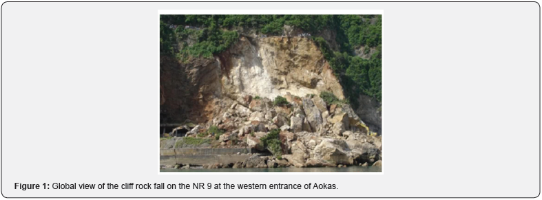
A spectacular cliff rock fall occurred on May 9th, 2005 covered the roadway of National Road N° 9 on a about 150m linear (Figure 1), at the entrance to the Aokas town (Figure 2). These rocks fall, preceded by several rocks, have not made a victim. The traffic on this busy road, the only way of communication between neighboring districts: Jijel and Béjaïa (about 20,000 vehicles/day) was completely blocked for three weeks, isolating the Aokas city. The old national road, located 60m beneath the modern one, was completely destroyed and constraining residents to a long detour to join Béjaïa. An important water pipe was also damaged leading to severe restrictions for the population. The rocks fall, which mobilized some 20,000 to 30,000m3 of rock materials was alienated from a fractured limestone cliff at the entrance to a small tunnel that overlooks the city of Aokas (Figure 1). The fallen rocks are fragmented into blocks of any size, with more than 100m3. This paper describes the geological and structural setting of the site and the safety work made (topometric monitoring, passive nailing of the new rock slope).

- Research Article
- Abstract
- Introduction
- Geology
- Tectonic
- Seismicity of the Aokas Region
- Karstification
- Description of the Rock Fall
- Topometric Mnitoring of the Rock Fall Scar
- Geotechnical Characteristics
- Strengthening of the Rocky Slope
- System of a Realized Reinforcement
- Proposal Optimization of the Sizing
- Results and Discussion
- Conclusion
- References
Geology
Aokas city is bordered in the west by a limestone massif of the Lower Jurassic [1]. These hard limestones, of dark grey color and brown patina form the skeleton of the Mount Imma Tadrart (Figure 3). Most of the outcrops show intense deformations which expressed themselves by fractures more at least closed and papered with calcite and with deposits of iron oxides. A feature of Calcareous breach fairly homogeneous and finely cemented intercalates into this massive limestone. They probably correspond to a weakness area [2]. Locally, coarse colluviums cover the steep slopes of this relief. Along the spur rocky which dominates the sea, and sometimes in alternation with colluvions, we find veneers of gravelly terraces marine origin (Figure 4). The height difference between the roof of these former terraces (Quaternary), and the level of current sea (Figure 4) testify, not of the eustatisme phenomenon, but the shore uplift by recent and very active tectonic movements. For example, the superficial earthquake of Boumerdès engendered a spectacular coast uprising, about 50km linear, esteemed to 75cm near the epicenter, then decreasing gradually to become null in Cape Djinet, approximately 35km on the West of Tigzirt [3].
- Research Article
- Abstract
- Introduction
- Geology
- Tectonic
- Seismicity of the Aokas Region
- Karstification
- Description of the Rock Fall
- Topometric Mnitoring of the Rock Fall Scar
- Geotechnical Characteristics
- Strengthening of the Rocky Slope
- System of a Realized Reinforcement
- Proposal Optimization of the Sizing
- Results and Discussion
- Conclusion
- References
Tectonic
The calcaro-dolomitic massif of Cape Aokas is affected by a strong deformation due to the Miocene alpine paroxysmal phase [4]. It is crossed by a big vertical fault N010 °E (Figure 3). The fault extension towards the south bounds the massif calcareous and controls its morphology. It is characterized by a thick zone of breaches. Two families of faults were identified. The first one presents a direction N015 °E to N045 °E; it is about faults having replayed into normal faults (Figure 5), at the origin of break mechanisms in the versant of sliding plan type to the northwest [5]. The second family presents a direction N080 °E to N100 °E quasi-parallel to the cliff forehead.
The Figure 6 shows the fracture caused by the tectonic constraints undergone by the rock during its geologic history. They present, generally, the same orientation as the fractures families observed in the Cape Aokas tunnel [2,5,6]. These analyses confirm the existence of three main directions, the first one oriented N015 °E to N055 °E with a dip of 40° to 86° to the northwest and the second is oriented N085 °E to N100 °E with a dip of 60° to 75° northward. The most important fractures are replayed to the faults collapses. The third fracture family is oriented N120 °E to N155 °E with a dip of 44° to 50° to the northeast. The opening spaces and discontinuities are very variable; they contain calcite crystallized and iron oxide deposits [5].

- Research Article
- Abstract
- Introduction
- Geology
- Tectonic
- Seismicity of the Aokas Region
- Karstification
- Description of the Rock Fall
- Topometric Mnitoring of the Rock Fall Scar
- Geotechnical Characteristics
- Strengthening of the Rocky Slope
- System of a Realized Reinforcement
- Proposal Optimization of the Sizing
- Results and Discussion
- Conclusion
- References
Seismicity of the Aokas Region
Béjaïa province has recorded during these last year’s relatively numbers of high magnitude earthquakes:
a. In March 2006, an earthquake of energy magnitude of 5,0Mw (USGS) has affected the Laâlam region at Kherrata [7], approximately 15km in the southeast of the study area. The earthquake caused the reactivation of the former sliding and the falls of blocks since limestone cliffs at Melbou [8].
b. In November 2012, an earthquake of magnitude Mw of 5,1 (CRAAG) which the epicenter was situated 9km in northeast of Béjaïa city and in 10km of the study area.
c. In May 2013, an earthquake of a magnitude Mw=5, 5 (CRAAG) which the epicenter was situated to 6km east of the study area.
In Aokas area, an earthquake of magnitude (Mw) superior to 5 can thus reactivate or activate diverse ground movements by disturbance of the initial equilibrium conditions. So, a versant with abrupt slope, stable under static conditions can be in imbalance under dynamic solicitation. The best examples are the rock fall and the landslides of Beni Ourtilane in 2000 (Mw=5,6) and Laâlam in 2006 (Mw=5,0) [9]. The seismic activity in Aokas area and the ground movement risks have obliged the authorities to look for a solution to stabilize the rocky slope cleared by the rock fall of May 2005 and to set up a device of measures allowing evaluating the slope deformations, in the wait to the realization of the reassurance works.
- Research Article
- Abstract
- Introduction
- Geology
- Tectonic
- Seismicity of the Aokas Region
- Karstification
- Description of the Rock Fall
- Topometric Mnitoring of the Rock Fall Scar
- Geotechnical Characteristics
- Strengthening of the Rocky Slope
- System of a Realized Reinforcement
- Proposal Optimization of the Sizing
- Results and Discussion
- Conclusion
- References
Karstification
A Jurassic limestone particularity of Aokas Cape is the presence of natural dissolution cavities. The fairy cave, where the entrance is situated in the tunnel (Figure 7), nearby the place where the rocks have fallen, witnessing the strong aptitude of this training to the karstification.

- Research Article
- Abstract
- Introduction
- Geology
- Tectonic
- Seismicity of the Aokas Region
- Karstification
- Description of the Rock Fall
- Topometric Mnitoring of the Rock Fall Scar
- Geotechnical Characteristics
- Strengthening of the Rocky Slope
- System of a Realized Reinforcement
- Proposal Optimization of the Sizing
- Results and Discussion
- Conclusion
- References
Description of the Rock Fall
At the west entrance of the Aokas city, the tunnel head is extended by a protection system with the armed concrete, to straight of the conglomeratic slope, susceptible to generate falls of small blocks. The rock fall occurred simultaneously (or with training effect) at the level of two distinct geological formations from the upstream slope of the NR 9:
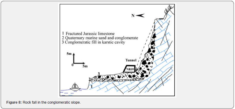
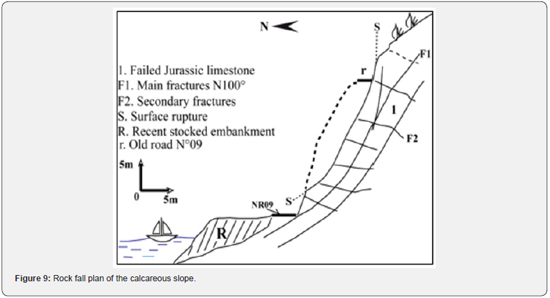
I. At the level of the calcareous slope (Figures 8 & 9), after removing the collapsed rocks, a net discontinuity in the surface was discovered, corresponding to one of the main rock fracturing plans. This plan (s) (Figure 8), of direction N080 °E to N100 °E quasi-parallel to the NR 9, present a dip downstream of 60° to 75°, completely unfavorable to the rocky slope stability. According to the statistical analysis of the fractures measures and the geologic cup realized along the collapsed slope, a new rock fall of big mass occurring is possible according to the plan F1 (Figure 8) with same mechanism of “sliding plan”.
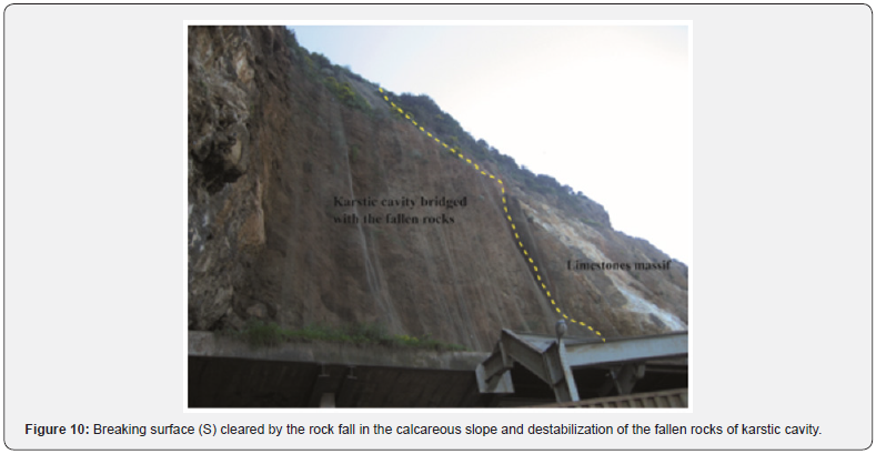
II. The conglomeratic slope (Figure 9 & 10), situated at the tunnel entrance, presents a relatively low resistance because of a partial cementation and alteration in the surface. His stability state limit is improved by the structure construction of concrete protection armed extending the tunnel. This structure largely destroyed by the calcareous blocks of the rock fall in May 2005. It was intended to protect the road users and resist to the falls impacts of small blocks. The attentive observation of the conglomeratic slope cleared by the rock fall, in the tunnel entrance, shows that it is about a material of karstic cavity filling (Figures 9 & 10). This cavity, of downward flared shape, is extended upward, as high as the former NR 9, by an open and shrunk section, and allowed the accumulation of masses fallen rocks. The presence of marine pudding (pebbles and sands with fossils fragments) which appears near the shore (Figures 4 & 10) and which extended to the karstic cavity basis; show that the latter was opened towards the sea, before its filling. The realized horizontal poll data in the cavity conglomerates show that the latter is of low extension. The visit of the “magic caves” accessible from the former tunnel and approximate location of the big room shows that this one is separated from the collapsed cavity by a thick rocky panel of 20m to 30m. The conglomeratic slope stability after rock fall remains precarious. The important problem at the Short-term is the frequent falls of small blocks, and not a new rock fall.
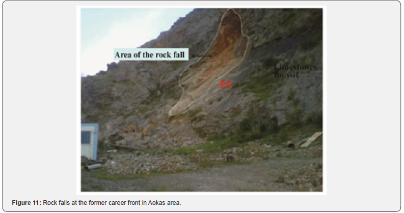
On April 2014, a rock fall of about 100m3 is occurred in the Cape Aokas calcareous massif at the level of the former career front (Figure 11), upstream the former NR 9 and in 1, 1km to the rock fall area of May 2005. The plan cleared by this rock fall corresponds to stratification plan (PS), of direction included between N050 °E and N060 °E with a downstream dip of 70°. Recently, in February 2015, seven persons were killed, and 20 others injured by a rocks fall near the Cape Aokas tunnel (500m of the head West, Tala Khaled) in Pk 26 of the NR 9 at the East of Béjaïa (Figure 12).
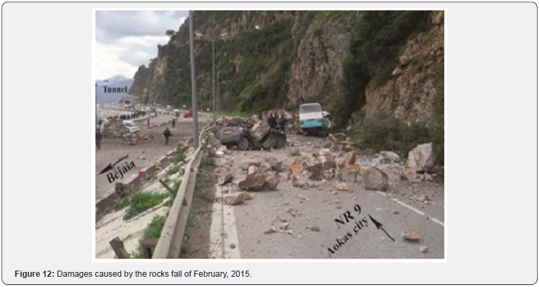
The rocks fall is occurred in outside period of frost after an episode of moderated precipitation between February 14th and February 21st, 2015 (36mm to Béjaïa, Station of Béjaïa- Airport). Since the beginning of 2015, the North of Algeria knew a moderate seismic activity, Especially the Western and the Southern of Algiers. No earthquake of magnitude superior then 3 was registered in the region of Béjaïa.
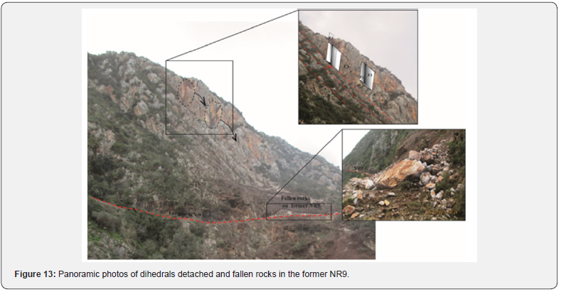
This spectacular rock fall mobilized about 50m3 to 100m3 rocky materials. According to witnesses, the first phase of rocks fall corresponded to the detachment of two dihedral unitarian volume esteemed between 3 and 5 m3 from a rocky bar, at a height of 160m of the current road (Figure 13). These two dihedrals have provoked the fall and the other blocks detachment of different volumes in the versant unstable equilibrium. The observations and the made measures show that both collapsed compartments were bounded by three plans. The first two correspond to both fractures families (F1 and F3) and the third plan corresponds to the stratification plan, a direction between N050 °E and N060 °E with an unfavorable downstream dip of 70°.
- Research Article
- Abstract
- Introduction
- Geology
- Tectonic
- Seismicity of the Aokas Region
- Karstification
- Description of the Rock Fall
- Topometric Mnitoring of the Rock Fall Scar
- Geotechnical Characteristics
- Strengthening of the Rocky Slope
- System of a Realized Reinforcement
- Proposal Optimization of the Sizing
- Results and Discussion
- Conclusion
- References
Topometric Mnitoring of the Rock Fall Scar
Since May 2005, the both calcareous and conglomerate slopes did not present a noteworthy instability. After the rock fall of April 2014 in the same massif, six topographic marks for the realization of infrared geodesic measures were set up on the potentially unstable compartments at the level of the rock fall scar of May 2005. The measures results of the totals displacements between April and September 2014 in six marks are represented on the graphs of the Figure 14 below.
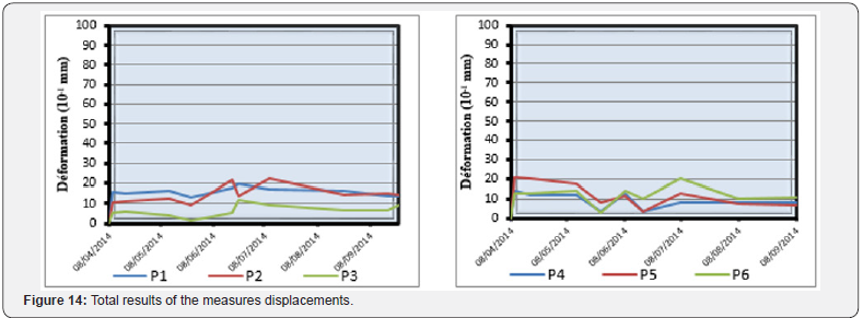
From totals results of displacements made during a period of six months, we notice that:
i. Until June 2014, the measures displacements remained lower than 2mm.
ii. During the summer period, characterized by an important tourist activity and very dense road traffic on the NR9, the displacements measures varied between 0, 5mm and 2, 3mm.
iii. Since the beginning of august, 2014, no deformation was recorded.
The total displacements measured remained lower than 2, 5mm, thus lower to the uncertainty of measure.
During the same period, some compartments localized in the downstream slope, the visual observations highlighted an opening of fractures. This movement of the millimeter-length order (lower than 10mm) occurred at the level of two fractures plans oriented N080 °E to N090 °E with a downstream dip of 65°.
- Research Article
- Abstract
- Introduction
- Geology
- Tectonic
- Seismicity of the Aokas Region
- Karstification
- Description of the Rock Fall
- Topometric Mnitoring of the Rock Fall Scar
- Geotechnical Characteristics
- Strengthening of the Rocky Slope
- System of a Realized Reinforcement
- Proposal Optimization of the Sizing
- Results and Discussion
- Conclusion
- References
Geotechnical Characteristics

γh: Volume weight (Natural water content).
wn: Natural water content.
Sr: Degree of saturation.
Rc: Simple compression resistance.
Is50: Compression resistance index between points for a distance inter-points equals in 50mm (Franklin test).
E: Module of Young.
Rtb: Indirect traction resistance (Brazilian test).
RQD: Rock Quality Designation.
The laboratory testing results realized during the doubling works of Cape Aokas tunnel on samples taken in a horizontal poll realized near the rocks fall of May 2005 are summarized in the following Table 1:
We notice that:
a. The compression resistance values are relatively lower with regard to Franklin index with a report Rc/Is50 of the order of 9 while this report is usually between 20 to 30.
b. The Young module values are relatively low compared with compression resistance values with a report E / Rc of the 142 order while this report is usually of about 250-750 order for this rock type.
c. The average RQD values vary from 21% to 78%, with a bad massif quality until 5m of depth and good one beyond 5m of depth.
In synthesis, the matrix is weakly resistant and is averagely stiff. It is characterized of a porous limestone (presenting an order of 10 % total porosity). It is indeed possible that in the proximity of the major vertical fault of direction N010 °E met at the oriental border level of the rocks fall, limestone is transformed to dolomite during an intense activity period (Dolomitisation of replacement and recrystallising having been able to destroy the limestone original texture), then by time (at the origin of dissolution phenomena in the mass and thus micropores).
- Research Article
- Abstract
- Introduction
- Geology
- Tectonic
- Seismicity of the Aokas Region
- Karstification
- Description of the Rock Fall
- Topometric Mnitoring of the Rock Fall Scar
- Geotechnical Characteristics
- Strengthening of the Rocky Slope
- System of a Realized Reinforcement
- Proposal Optimization of the Sizing
- Results and Discussion
- Conclusion
- References
Strengthening of the Rocky Slope
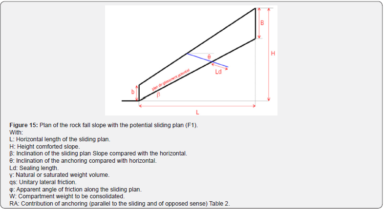
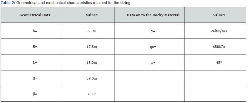
The nailing solution of the rocky slope by passive anchoring was retained with a sizing to the limit balance for the following hypotheses:
I. The absence of cohesion and water pressure along the potential sliding plan,
II. The seismic zoning established by the Earthquakeresistant Genius Center (CGS, on 1999) modified and completed further to Boumerdès earthquake in 2003, class the Aokas region in average seismicity area (area II a). For the justification in pseudo-statics of an important vital structure from the view safety point, the horizontal acceleration coefficient of the reference earthquake to be taken into account is equal in: σH=0, 25. The vertical acceleration coefficient σV is equal to the third of the coefficient σH,
III. The anchoring steel working rate is limited in the middle of the elastic limit under static solicitation (except earthquake) and to the elastic limit under seismic solicitation,
IV. The sealing length beyond the potential sliding plan is the maximal value between the value deducted from traction test on nail (allowing reaching the unitarian side friction noted qs) and a fixed value equals 70 times the diameter of the anchoring steel bars.
Consider the hypotheses exposed above and those exposed on the schematic (Figure 15) and in the Table 2 below, the rocky slope safety factor towards the sliding plan, noted Cs, can be calculated in the equilibrium limit according to the following relations:
a) Slope not strengthened except seismic solicitation:

b) Slope not strengthened under seismic solicitation (with vertical component oriented upward):

c) Slope strengthened except seismic solicitation:

d) Slope strengthened under seismic solicitation (with vertical component oriented upward):

- Research Article
- Abstract
- Introduction
- Geology
- Tectonic
- Seismicity of the Aokas Region
- Karstification
- Description of the Rock Fall
- Topometric Mnitoring of the Rock Fall Scar
- Geotechnical Characteristics
- Strengthening of the Rocky Slope
- System of a Realized Reinforcement
- Proposal Optimization of the Sizing
- Results and Discussion
- Conclusion
- References
System of a Realized Reinforcement
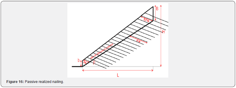
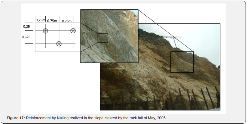
The realized strengthening System is consisted of steel bars with an equal diameter of 20mm and elastic limit equal to 950MPa, setting place in drillings of an equal diameter of 90mm and tilted by 20° with regard to the horizontal, with an average square stitch of 0, 71m x 0, 71m (Figure 16). The length of sealed bars at the back of potential sliding plan (F1) (Figure 8) is fixed to 6m on the other hand the total length of bars is determined according to their position in the slope. It varies between 8 m and 11, 5m (Figure 17).
The reinforcement, thus validated by the contracting authority, is widely oversized with safety factors equal in:
a) 3,4 without earthquake,
b) And at 5, 1 under reference earthquake.
The reinforcement rests on small diameter bars (without consideration the reduction bound to the corrosion), in steel very stiff and according to a small dimensions square stitch, induced an intense cutting of the rock massif. The remainder of article presents a possible optimization of the nailing.
- Research Article
- Abstract
- Introduction
- Geology
- Tectonic
- Seismicity of the Aokas Region
- Karstification
- Description of the Rock Fall
- Topometric Mnitoring of the Rock Fall Scar
- Geotechnical Characteristics
- Strengthening of the Rocky Slope
- System of a Realized Reinforcement
- Proposal Optimization of the Sizing
- Results and Discussion
- Conclusion
- References
Proposal Optimization of the Sizing
The dimensioned situation is the one without earthquake with the same data used previously. The safety factor aimed after strengthening is Fs=1, 3.
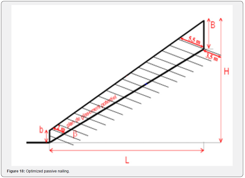
The bars implementation an equal diameter of 50mm (with a reduction of 8mm in diameter among 100 years due to the corrosion) and of elastic limit equal to 500MPa, with an average square stitch of 2,04m x 2,04m, allows to result in equal safety coefficient in:
a. 1,3 without earthquake,
b. And in 1,6 under reference earthquake.
The length of sealed bars in the back of the potential plan sliding (F1) (Figure 8) will be at least 3, 5m at the back of the unstable potentially plan (F1). The bars total length is determined according to their position in the slope. It is between 5m and 9m (Figure 18).
- Research Article
- Abstract
- Introduction
- Geology
- Tectonic
- Seismicity of the Aokas Region
- Karstification
- Description of the Rock Fall
- Topometric Mnitoring of the Rock Fall Scar
- Geotechnical Characteristics
- Strengthening of the Rocky Slope
- System of a Realized Reinforcement
- Proposal Optimization of the Sizing
- Results and Discussion
- Conclusion
- References
Results and Discussion
The rock fall of Cap Aokas (May 2005) on the west side of the current RN9 tunnel is occurred following a fracture oriented N087° to N090°. The released plan by the rock fall shows continuity over several m2, a regularity of its surface that is smooth enough and may distorted. It presents a precarious stability. The obtained safety coefficients in both situations (excluding earthquake and under reference earthquake) show that the realized retaining system is oversized (steel bars with a diameter of 20mm, yield stress equal to 950MPa, drilling with a diameter of 90mm and inclined at 20° relative to the horizontal, average square mesh of 0.71m x 0.71m and a length of the bars sealed behind the potential sliding plane set at 6m), we wonder if its size is not excessive. However, the mesh of small dimensions, can induce intense cutting of the rock mass under the reference earthquake. The optimization of the design shows that the proposed retaining system ensures the stability of the slope in both situations excluding earthquake and under reference earthquake
- Research Article
- Abstract
- Introduction
- Geology
- Tectonic
- Seismicity of the Aokas Region
- Karstification
- Description of the Rock Fall
- Topometric Mnitoring of the Rock Fall Scar
- Geotechnical Characteristics
- Strengthening of the Rocky Slope
- System of a Realized Reinforcement
- Proposal Optimization of the Sizing
- Results and Discussion
- Conclusion
- References
Conclusion
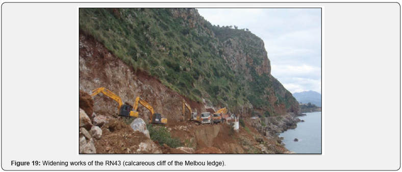
In the study term of the reinforcement project of the rock fall scar of May 2005, the various aspects (geology, fracturing of the massif, the seismicity and geotechnical) allowed us to end in a detailed analysis of the slope stability. Small diameter bars (without consideration of a possible reduction bound to the corrosion in marine environment), very stiff steel and a small square stitch (induce an intense cutting of rock massif). The reinforced slope will have to be considered as a sensitive structure and be the specific surveillance object by the contracting authority (Periodic inspections, follow-up by infrared geodesic measures). This new rock falls put in evidence the necessity of detailed diagnosis towards the rocky risk on the threatened whole section of the NR9, on a linear about 1, 2km. A particular attention will have to be given to the strengthening sizing by passive nailing of the unstable rocky slope in the Melbou ledge after the completion works of the NR43 extension (Figure 19), situated in approximately 15km east of Aokas area.
- Research Article
- Abstract
- Introduction
- Geology
- Tectonic
- Seismicity of the Aokas Region
- Karstification
- Description of the Rock Fall
- Topometric Mnitoring of the Rock Fall Scar
- Geotechnical Characteristics
- Strengthening of the Rocky Slope
- System of a Realized Reinforcement
- Proposal Optimization of the Sizing
- Results and Discussion
- Conclusion
- References
References
- Leikine M (1971) Etude géologique des Babors occidentaux (Algérie). Thèse de doctorat. Université de Paris, Paris, France.
- Bougdal R (2009) Doublement du tunnel de Cap Aokas, synthèse des données géologiques et géotechniques.
- Meghraoui M, Maouche S, Chemaa B, Cakir Z, Aoudia A, et al. (2004) Coastal uplift and thrust faulting associated with the M=6.8 Zemmouri (Algeria) earthquake of 21 May 2003. Geophysical Research Letters 31(19): 2004.
- Kirèche O (1993) Evolution géodynamique de la marge tellienne des Maghrébides d’après l’étude du domaine parautochtone schistosé. Thèse doctorat sciences, Université d’Alger (USTHB), Alger, Algeria.
- Hallal N, Bougdal R, Bensafia W (2013) Dédoublement du tunnel d’Aokas (BEJAIA): géologie et caractérisation géotechnique du massif traversé. Stabilité de l’ouvrage. Bull Eng Geol Environ 3(4): 2013.
- Bensafia W, Hallal N (2011) Dédoublement du tunnel d’Aokas (BEJAIA): géologie et caractérisation géotechnique du massif traversé. Mémoire Master, USTHB, Algeria.
- Machane D, Guillier B, Chatelain J, Bouillin B, Haddoum H, et al. (2009) Le séisme de Laâlam (Kabylie, Algérie) du 20 mars 2006: prospections géologiques et géophysiques (bruit vibration ambiant) et corrélations avec les dommages. Bull du service géologique national 22(3): 357- 373.
- Beldjoudi H, Guemache MA, Kherroubi A, Semmane F, Yelles-chaouche AK, et al. (2009) The Laâlam (Béjaïa, North-East Algeria) Moderate Earthquake (Mw=5.2) on March 20, 2006. Pure appl geophys 166: 623–640.
- Bouhadad Y, Nour A, Laouami N, Belhai D (2003) The Beni-Ourtilane- Tachaouaft fault and Seismotectonic aspects of the Babors region (NE of Algeria) Journal of Seismology 7: 79-88.


