Experimental Evaluation of Concrete Slab Using Hollow Steel Pipes
Rajeshwaran R*, Yamini V, Nivedha DGS and Madhu Bala AM
Department of Civil engineering, VEL Tech University, India
Submission: May 10, 2018;Published: June 26, 2018
*Corresponding Author: Rajeshwaran R, Department of Civil engineering, VEL Tech University, Tamil Nadu, India, Email: rajeshwaran442@gmail.com
How to cite this article: Rajeshwaran R, Yamini V, Nivedha D, Madhu B A. Experimental Evaluation of Concrete Slab Using Hollow Steel Pipes. Civil Eng Res J. 2018; 5(4): 555670. DOI:10.19080/CERJ.2018.05.555670
Abstract
An extensive experimental investigation with the aim of studying the structural behavior of slabs on load bearing capacity and deflection, using steel hollow pipes is presented in this paper. A Reinforced Concrete Slab is the one of the most important structural component in a building. In today’s world of innovation and fast-tracking, the hollow-core slab is a viable and in many instances, preferable alternative to more conventional building methods. In composite construction, the most common combination of these materials is concrete and steel, producing a composite material where the bending moment caused by a static load is mainly resisted by the compressive force in the concrete and the tensile force in the steel. Probably the most common element is composite slabs, which is an efficient and popular alternative for floor slab construction. In this paper load bearing capacity and deflection of conventional concrete slab is compared with concrete slab using hollow steel pipes. The experiment has been carried out using different diameters of steel hollow pipes and it is found that there is not much variance in load bearing capacity of slabs.
Keywords: Composite slabs; Hollow steel pipes; Deflection; LBC
Introduction
General
Continuous rise in the prices of steel reinforcement and cement leads, to the search for ways to reduce the weight of the concrete. This reflects on the total cost of the construction project. This also has a significant effect on environmental problems caused by use of huge amounts of cement and steel [1]. Several researches studies focused on reducing the bulk density of concrete, by making a hollow core in concrete columns wrapped with using fiber (FRP) rein for cement. Other research studies focused on the effect of hollow core on the behavior of reinforced concrete slabs. More work was performed on the performance of hollow in pre- stressed concrete sections.
A hollow core slab is a precast pre stressed concrete member with continuous voids provided to reduce weight and cost. They are primarily used as a floor deck system in residential and commercial buildings as well as in parking structures because they are economical, have good fire resistance and sound insulation properties, and are capable of spanning long distances with relatively small depths. Structurally, a hollow core slab provides the efficiency of a prestressed member for load capacity, span range, and deflection control [2]. Hollow core slabs can make use of prestressing strands, which allow slabs with depths between 150 and 260 mm to span over 9 meters.
Precast prestressed hollow core slabs provide maximum structural efficiency with the utilization of high strength concrete, yet at the same time requiring low material consumption. This hollow core slabs are primarily used as a floor deck system in residential and commercial buildings as well as in parking structures.
Material Test Results
Cement
Physical properties of cement:
1. Fineness– 2%
2. Consistency– 30%
3. Initial setting time– 45 min
4. Final setting time– 520 min
5. Specific gravity– 3.15
Fine Aggregate
Physical properties of fine aggregate:
1. Fineness– 4.136%
2. Grading zone III
3. Moisture content– 2.4%
4. Water absorption– 0.8%
5. Specific gravity– 2.65
Coarse Aggregate
Physical properties of coarse aggregate:
1. Fineness– 3.713%
2. Nominal size– 10 mm
3. Moisture content– 0.93%
4. Water absorption– 0.6%
5. Specific gravity– 2.68
Mix Ratio for M30 (as per IS 10262: 2009)
Mix proportion = 1: 2.4 : 2.5
Experimental Investigation
Casted specimens
1. RCC Slab (1200mm x 600mm) - CS
2. Composite slab (1200mm x 600mm) with hollow pipe section of 42mm diameter - 1.6mm thickness - CSS1
3. Composite slab (1200mm x 600mm) with hollow pipe section of 32mm diameter - 1.6mm thickness - CSS2
4. Composite slab (1200mm x 600mm) with hollow pipe section of 32mm diameter - 2mm thickness - CSS3
Form work construction and initial assembly
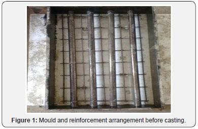
The form work construction and initial assembly involved the cutting and welding of steel plate with 100mm thickness and assembling the form work and edge mouldings. The mould is fabricated and the setup is arranged ready for the casting [3]. The outer side is given a two layer coating of paint so as to prevent it from rust. Since oiling at a later time would be difficult once the steel cage was assembled, formwork pieces that were in place were oiled in preparation for casting (Figure 1).

Concrete casting
The final phase of construction was casting the specimen. The base and body of the slab were cast simultaneously in two layers respectively. A large vibrator was used as the primary means of compaction. In addition compaction rod is used at the areas where the column was congested with steel [4]. The concrete surface was leveled and finished with trowels (Figure 2).

Experimental test setup
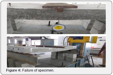
The experimental set up includes assembling the instrumentation and test apparatus. The test specimen is slowly lifted using two steel ropes hooked on the handles of the slab and placed on the loading frame. The base of the slab is fixed with the loading frame. The Proving ring is used to measure force. Forces are applied to it through Hydraulic jack. The micrometer dial gives the deflected values. The Proving ring used here is of 50 ton capacity. For the axial loading, the hydraulic jack is placed laterally near the top middle of the slab. Hydraulic jack generally used to apply load. Here 100 ton capacity of hydraulic jack is used. The pressure is given by Hydraulic pump of capacity 100 ton (Figure 3 & 4). To check the displacement dial gauges with 50mm are placed at bottom of the slab.


Result and Discussion
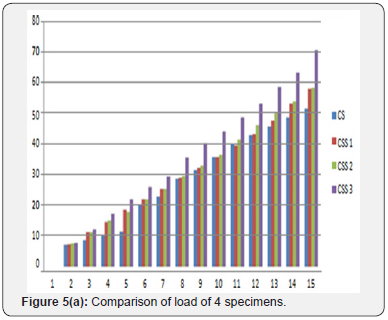
On comparing the loading pattern of 4 specimens the conventional slab did not take much load whereas the composite section performs well. The below graph clearly shows the performance under loading of all the specimens.
The performance of steel pipe is more important. So with the data of load to diameter of the specimens we may conclude that the load carrying capacity is almost same for the 32mm and 42 mm dia steel pipe [5]. The graph shows the loading pattern for the sections having different diameters and thickness of pipes (Figure 5a).

The change in diameter of steel pipe has no effect in section based on loading. The difference in thickness of steel is another criteria to be considered. The 32mm diameter of 1.6mm thickness steel pipe and the 32mm diameter of 2mm thick steel pipe is compared (Figure 5b). This gives a difference in load of 1kN.

The main phase of the project is the amount about which the section displaces. This must be keenly noticed because this is the main effect during maximum loading. It was the route cause for the selection of composite section in case of RC. On comparing the displacement of RC slab versus composite slab we get a half reduction of values for the composite section. Hence, we may conclude that the choice of composite section for maximum loading is correct [6]. It is having a good response that the building won’t damage on heavy shakings.
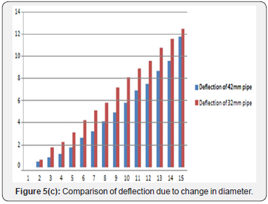
Further, the choice of the steel section has to be noticed. It is clear that the when the thickness is increased there is no much difference in displacement [7]. The values are alike. This make us to conclude that the increase in thickness do not effect the deflection. But when the diameter is increased we have a difference of 5mm between the 42mm and 32mm (Figure 5c).

Conclusion
a. The composite section is best for the maximum load performance than the normal RC slab.
b. The change in diameter do not affect the performance of specimen.
c. When the thickness of the pipe is increased the load carrying capacity is also increased.
d. When the diameter of the pipe is increased the deflection is decreased
e. If we make the cost wise comparison, the composite section is economical only. Due to the use of hollow section the self weight is reduced up to 1.5% on comparing with the control specimen.
Future Scope of the Work
Since, we got a satisfactory results with the composite section we can make use of it in future. It can be used in earthquake prone areas. The results can be used in further for the moredetailed analysis of seismic study. For the test of cyclic loading these values are more important. The composite slab have many applications in industrial as well as in residential.
References
- Gamal AA (2015) Strengthening Techniques in Reinforced Concrete Hollow Core. International Journal of Engineering and Innovative Technology (IJEIT) 4(8): 159-173.
- Woods LJ, Bull DK, Fenwick RC (2008) The Seismic Performance of Hollow-Core Flooring: The significance of negative bending moments. The 14th World Conference on Earthquake Engineering, Beijing, China.
- Vidya Jose, Rajeev Kumar P (2014) Hollow Core Slabs in Construction Industry. International Conference on Innovations & Advances in Science, Engineering and Technology 3(5): 414-420.
- Sameer Kumar Sarma P, Suriya Prakash S (2015) Performance of Prestressed Hollow core Slabs with and without Cutouts. International Journal of Research in Engineering and Technology 4(13).
- Monisha KM, Srinivasa G (2017) Experimental Behaviour of Prestress Hollow Core Slab, Rc Hollow Core Slab And Normal Rc Solid Slab. International Research Journal of Engineering and Technology (IRJET) 4(4): 1090-1093.
- Sorelli LG, Alberto Meda, Giovanni Plizzari (2006) Steel Fiber Concrete Slabs on Ground. ACI Structural Journal 103(4): 551-558.
- Hrynyk TD, Vecchio FJ (2014) Behavior of Steel Fiber-Reinforced Concrete Slabs under Impact Load. ACI Structural Journal, Engineering and Technology 111(5): 1213-1224.


