


A Simple Engineering Soil Surface Vibration Prediction Method
Darius Macijauskas1 and Stefan Van Baars2*
1ArcelorMittal Commercial RPS, Luxembourg
2Professor in Foundation Engineering and Soil Mechanics, Faculty of Science, Technology and Communication, University of Luxembourg, Luxembourg
Submission: January 09, 2018 Published: March 27, 2018
*Corresponding author: Stefan Van Baars, Faculty of Science, Technology and Communication, University of Luxembourg, Campus Kirchberg 6, rue Richard Coudenhove-Kalergi, Luxembourg, Tel: 00352 466644 5801; Email: stefan.vanbaars@uni.lu
How to cite this article: Darius M, Stefan V B. A Simple Engineering Soil Surface Vibration Prediction Method. Civil Eng Res J. 2018; 4(2): 555632. DOI: 10.19080/CERJ.2018.04.555632
Abstract
In urban areas where the infrastructure is dense and construction of new structures is near existing and sensitive buildings, frequently vibrations, caused by human activities, occur. Generated waves in the soil may adversely affect surrounding buildings. These vibrations have to be predicted a priori by using currently available knowledge of the soil dynamics. In order to make a good prediction of the soil surface vibration, it is necessary to perform calculations with a Finite Element Method (FEM). The disadvantages of the FEM are that this requires a special software package and a long time for the modelling and calculations. Therefore, it would be very useful to derive a simple model for engineering purposes, which could be used to predict geotechnical vibrations close to the source, without the need of special software and long calculations. Such a method is proposed in this article. This method is validated by a vibration test performed on a peaty site in the Netherlands. The predictions made with this method, have been compared with both the field measurements and the FEM calculations. The comparison proves that by using the presented vibration prediction method, the vibrations can be predicted as accurate as with the FEM.
Keywords: Soil vibration; Surface vibrations; Soil dynamics; Oscillating foundations; Vibration prediction
Introduction
For most developing countries, the urban environment is getting larger and denser. Therefore, geotechnical engineers have to pay more attention to the effect of vibrations caused by different human activities. Unfortunately, most of the methods for vibration predictions currently used by practitioners are empirical. According to Hölscher and Waarts [1], the quality of the predictions made with current vibration prediction methods is disappointingly low). They concluded that, in order to make an accurate prediction of the soil surface vibration, it is unavoidable to perform calculations with the Finite Element Method (FEM). The disadvantages of the FEM are that it requires a special software package and it takes a long time for the modelling and performing the calculations. Therefore it would be very useful to have a simple analytical method for engineering purposes, which could be used to predict geotechnical vibrations close to the source without the need of special software and long calculations.
For the development of such a method to predict soil surface vibrations close to an oscillating circular foundation, data from recent vibration experiments [2] has been be used.
Vibration Tests
The vibration tests were performed on a peaty site in the Netherlands. The top layer of the site is a thin clayey layer with a thickness varying between 0.2m and 0.5m. Below this layer, there is a peat layer of 4.5 m in thickness. The bulk density of this peat layer is P = 0.98± 0.08 t/m3 [3]. From P- and S-wave velocity measurements ( vp = 66.9 m/s, vs = 17.4 m/s), the following elasticity parameters were defined: G = 303 kN/m2, v = 0.464. A material damping ratio of % =1% used for peat, as recommended by Coelho [4].
The vibration test setup is presented in Figure 1. The source of vibration is the shaker, which consists of two counter rotating electric vibrators, a stiff circular bottom plate and dead mass on top to ensure that the oscillating force is always lower than the weight of the system. The plate radius rpl = 0.2m and the thickness of 20mm makes it stiff enough to be treated as a rigid foundation. The vibration test was performed with a frequency f = 24 Hz. The distance between the edge of the oscillator and the geophones is 1,2,3,..m, see also Figure 2 & 3 and Table 1. Also a geophone is placed on top of the shaker.


The measured displacement amplitudes were compared with both the FEM results and the analytical solution given by Barkan. For the calculations the site was treated as a homogeneous elastic half-space with previously determined properties. The measured amplitudes vs. FEM and analytical solutions are shown in Figure 2.
From Figure 2, it can be seen that the near-field zone, which is defined by Barkan [5] as an interception of his near- and far- field solutions is rather short, only 0.73m. In addition, that the attenuation rate of the measured amplitudes is much higher just in the first meter. From this, it can be concluded that in the nearfield zone, the amplitude attenuation is much stronger, and in the far-field zone, the attenuation is not so strong anymore.
Here, the findings of the Wave Decomposition Technique [6] can also be recalled, where it was found, that a part of the dynamic displacement of the rigid plate could be explained by the elasto-static Boussinesq solution for a rigid plate.
In the vibration test on site, the amplitude of the vertically oscillating force can be calculated by knowing the eccentric moment Me and the frequency f as follows:

If this would be a static load on a rigid plate, according to the elasto-static solution of Boussinesq, the vertical displacement could be calculated as follows:
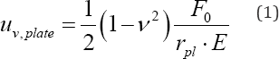
Where: V - Poisson's ratio; F0 - vertically oscillating force; rpi - radius of the shaker; E - elasticity modulus of the medium.
Having a Poisson's ratio v = 0.464, a vertical force F0 = 1.89kN, a radius of the plate rpl = 0.2m and a modulus of elasticity E =886kPa, the vertical static displacement of the rigid plate would be uvplate = 4185|im. This is 14.3 times higher, than the dynamic vibration amplitude of the plate, measured during the vibration test - 292|im (Figure 1). The factor 14.3 here comes from the soil-foundation interaction, which is similar to the behaviour of a mass-spring-dashpot system. The spring plays a static role and the wave propagation determines a dashpot (analogy of conductivity).
At this point, it will be assumed that the attenuation of the vertical dynamic displacement amplitudes near the oscillating plate (in the near-field) has the same attenuation as a half-space surface deformed by a vertically loaded rigid plate under static conditions. For the static case, the soil surface displacements near the rigid plate can be calculated by using a solution from the theory of elasticity:
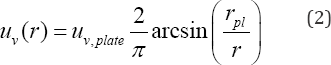
Where: r - the distance from the centre of the rigid plate to the point of interest.
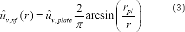
For the dynamic case, the dynamic vertical amplitude of an oscillating rigid plate should be used instead of the vertical static displacement. The dynamic amplitude of the plate can be calculated by Lysmer's method [7]. By using this, the vertical displacement amplitudes in the near-field are given by:
The start of the far-field will be taken approximately equal to the length of the R-wave ( rff = Xr ). In the far-field, mostly the Rayleigh waves dominate. Therefore, the attenuation law of the amplitudes is known to be proportional to r~05 . By taking the material damping into account, according to the law suggested by Bornitz [8], the far-field amplitudes will be:
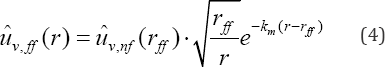
Where: ûv nf (rff ) - is the start of the far-field; uv,n/\ vertical amplitude from the near-field estimation; km - empirical absorption coefficient for material damping.
IfLysmer's solution is used for the dynamic plate displacement amplitude, Boussinesq's elasto-static solution is used for the amplitudes in the near-field and the R-wave attenuation law together with the material damping law suggested by Bornitz [8], are used for the far-field, the vertical vibration amplitudes can be calculated as follows:
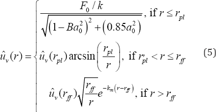
Where: k - spring coefficient for Lysmer's analogue; B - Lysmer's modified dimensionless mass ratio; a0 - dimensionless frequency ratio.
The spring coefficient of Lysmer’s mechanical analogue can be calculated as follows:
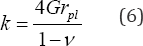
Where: G - the shear modulus of the soil; Lysmer's modified dimensionless mass ratio is defined as:
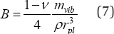
Where: mmb - the mass of the vibrating foundation; p - the density of the medium.
The dimensionless frequency ratio can be found as follows:
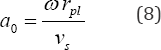
Where: W - the angular frequency; vs - the shear wave velocity.
Comparison with the field measurements
This approach was used for the post-diction of the measured amplitudes on site. A value of the absorption coefficient km = 0.09 m-1 is used for the far-field. This corresponds to a material damping ratio of £ = 1%. A comparison between the amplitudes of the post-diction and the measurements can be seen in Figure 3.
Predicted versus measured displacement amplitude ratios (P/M) have been compared with both the Barkan-Bornitz far- field solution and with FEM calculations, see in Table 1. This table shows that this simple method predicts just as accurate the amplitudes of vibration for the shaker test as the FEM.

Comparison with FEM calculations
The proposed prediction method gives results which are very close to the measurements. Besides, this method has also been validated by using FEM, for different frequencies f and different modified mass ratios B. This will be described below.
FE model
In order to model the vibration test numerically, Plaxis 2D software was used. The geometry of the FE model is shown in Figure 4.

For the soil medium, a linear elastic material model was used with the following properties: e �x003D; 1000kN/m2, �x003D; 0.25, and a unit weight �x003D; 20kN/m3. The shaker was modelled by a plate element with a very high stiffness to satisfy the rigid foundation assumption. Different plate weights were used in different calculations in order to correspond to the required modified mass ratio b . The calculations were performed with four different modified mass ratios b �x003D; 0.5, 1.0, 2.0 and 5.0 and for ten different frequencies ranging from 2 to 15Hz. The corresponding dimensionless frequencies a0 are listed in Table 2.

Four different modified mass ratios Band ten different frequencies j result in 40 displacement amplitude versus distance plots. The vibrations were calculated at nine different surface points (from 1m to 9m away from the centre of the plate).
Results
The FEM results of the surface vibration serve as validation of the developed method. It should be noted that in these FEM calculations, unlike the ones of the post-diction, the material damping is not used. Therefore, for the comparison of the developed prediction method discussed here, the Bornitz exponential part is not used either. Another difference j is the size of the near-field. In the post-diction the distance , where the near-field ends and the far-field begins, was assumed to be equal to the length of Rayleigh waves: r, =\. However analysing the FE modelling results it was noticed that the results have a better match by using half the distance, so j = 0H.
In order to compare the results between the developed model and FEM calculations, their errors will be expressed in a percentage, calculated as follows:
Where: andijFEX - vibration displacement amplitudes calculated by the developed method and by FEM, respectively.
In order to show all results separately, one would need 40 plots in total. Therefore the average errors of all 40 calculations are presented in Table 3, and the maximum errors in Table 4. The biggest average error of the 9 calculation points on the surface is 24.1%, which is fora dimensionless frequency a0 = 1.077 and a modified mass ratio b = 0.5.


Two representative plots were selected, in Figure 5 the results can be seen for the modified mass ratio B = 0.5, with frequency j = 12 Hz and in Figure 6 for B = 5 and j = 5 Hz.


Conclusion
For engineering purposes, a simple analytical vibration prediction method is developed to estimate the vibration amplitudes next to a harmonically oscillating rigid circular plate on an elastic half-space. This analytical method bridges two extremes-a pure mathematical approach, which requires knowledge of complex analysis and an empirical approach.
This solution consists of three parts: 1) the analytical Lysmer method for the plate displacement amplitude 2) the shape of the vertical surface displacements of the elasto-static Boussinesq solution in the near-field and 3) the R-wave attenuation law r-05 with the exponential material damping law (exp [km (r - rr)]) in the far-field. It can be assumed, that the near-field ends at a distance, which is about a half to one length of the R-wave.
This approach gives accurate predictions, in comparison to both the field measurements and FEM calculations.
References
- Hölscher P, Waarts PH (2003) Reliability of vibration prediction and reducing measures. Report Delft Cluster, Delft.
- Macijauskas D, Van Baars S (2014) Propagation of harmonical vibrations in peat.International Journal of Geomate 7(14): 1101-1106.
- Zwanenburg C (2013) De bepaling van sterkte-eigenschappen van veen. Geotechniek, p. 26-32.
- Coelho B (2010) Dynamics of railway transition zones in soft soils: Doctoral thesis. Delft: Delft University of Technology.
- Barkan DD (1962) Dynamics of bases and foundations. New York: McGraw-Hill Book Company Inc., USA.
- Macijauskas D, Van Baars S (2013) Decomposition of measured ground vibrations into basic soil waves, in 3rd International Symposium on Computational Geomechanics (ComGeo III), Poland, p. 21-23.
- Lysmer J (1965) Vertical motion of rigid footings. Report to WES Contract Report, Michigan: Department of Civil Engineering, University of Michigan.
- Bornitz G (1931) Über die Ausbreitung der von Großkolben Maschinen erzeugten Bodenschwingungen in die Tiefe. Berlin: Springer-Verlag.


