The Effect of Nail Inclination Angle on Improving the Performance of Nailing System in Vertical Excavation
Farzi M1* and Khodadadi R
1Department of Civil engineering, Islamic Azad University, Iran
2Shahid Chamran University of Ahwaz, Iran
Submission: July 17, 2017; Published: August 21, 2017
*Corresponding author: Mohsen Farzi, Islamic Azad University Abadan Branch, Abadan, Iran, Tel: +989167751042; Email: mohsen.farzi@gmail.com
How to cite this article: Farzi M, Khodadadi R. The Effect of Nail Inclination Angle on Improving the Performance of Nailing System in Vertical Excavation. Civil Eng Res J. 2017; 1(3): 555561. DOI: 10.19080/CERJ.2017.01.555561
Abstract
Nailing is one a soil stabilization system that has prevailed recently. This article investigates the effect of nailing angle on stability of a cut in each stage of excavation. The results are based on the analysis of a vertical cut 8m in depth in which8 nails are successively driven at a vertical distance of 1m during excavation. 6 meter nails are used at inclination angles of 0, 5, 8 and 10, as well as a state in which different angles are applied assuming that the nail is perpendicular to the critical soil wedge. It is concluded that performance of the nail is the most unfavorable at an angle of zero while the best performance is realized at different angles.
Keywords: Nailing; Optimum angle; Safety factor; Vertical cut; Geostudio 2012
Introduction
Over the past decades, the use of soil nailing has been increasing worldwide due to its implementation speed, relative simplicity and cost-effectiveness, by which a probably instable soil mass can be tied back to other parts with more favorable situations. The overall stability of the system depends on a variety of factors, including strength of the nail, length of the nail, nailing angle, soil type and the shape of soil mass being stabilized. Among the parameters stated, soil type and shape of the soil mass do not play a role in optimization due to the fact that they depend on natural and inherent characteristics of the soil; therefore, other factors must be noticed in order to improve and optimize performance of the system. A uniform distribution system is usually used for nail inclination and some methods have been studied in regard to nail's length and inclination angle. In a project carried out in the 1980s in France, for example, it was concluded that longer nails were better to be used on top of tall walls [1]. In other studies, it was also concluded that soil dilation angle was the most important soil parameter affecting the nail [2]and if pressure grouting was employed instead of gravity grouting, safety factor of the slope could significantly increase [3]or the highest risk of failure was seen in the lower part of the facing during nail driving [4]. In the studies carried out in this regard, as the some mentioned above, the investigation into stability and deformations was conducted when the entire wall was constructed so that the effects of nailing were examined ultimately. In this study, stability and changes during excavation are concerned because temporary stability of the cut prior to construction of the main structure is often impotent; so it is substantial to prevent massive failures in excavated walls.
Modeling
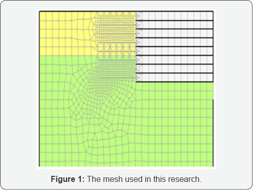
In this study, GeoStudio software is used for modeling and excavation steps are considered in term of one-meter phases. After nailing in each step, the stability and number of failure wedges are evaluated. The soil being studied is considered in term of three layers whose properties are presented in Table 1. The mesh used in this research is also presented in Figure 1.

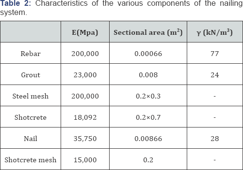
6 meter nails with a pull-out resistance of 100kN and the nailing system is investigated at various angles of 0, 5, 8, and 10 degrees. In another case, a critical soil wedge is considered instead of nailing at a constant angle, assuming that the nail is always perpendicular to the failure surface. The excavation cut is 8 meters in depth with one meter steps from the starting point to the depth of 8 meters. The shotcrete mesh is modeled in the same way step by step; the mesh made of steel and the shotcrete according to ACI (Table 2) cover 30% and 70% of the surface, respectively [5-7].
Equation (1) is applied to calculate equivalent elastic modulus of the shotcrete mesh and the nail.

where refers to elastic modulus of steel, refers to cross section area of steel, refers to elastic modulus of grout or shotcrete and refers to cross section area of grout or shotcrete. Moreover, since the minimum safety factor of wedges discussed below may be obtained from a wedge of low importance, the factor is modified by averaging safety factors of last ten wedges in their critical state.
Discussion and Assessment
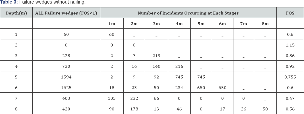
To investigate the effect of nailing on the cut, the excavation is assessed without lateral bracing and then with a nailing system. Therefore, in Table 3, sliding wedges occurring at each stage are listed along with the safety factor based on their depth. According to the results of Table 3, a few failure wedges are occurred to the depth of 2m in the excavation without lateral bracing, but the number of probable failure wedges rises after the depth of 2m. Since the entire excavation wall is deformed exponentially at a depth of 7m, Due to the fact that the whole wall of the hull has become noticeably deformed, the potential of failure is reduced in lower parts of the cut; but instabilities are probable to occur as more soil is removed successively. In the following, the nailing system is examined at angles of 0, 5, 8, and 10 with the horizontal, so that the results of displacements are initially estimated at nailing angle of zero.
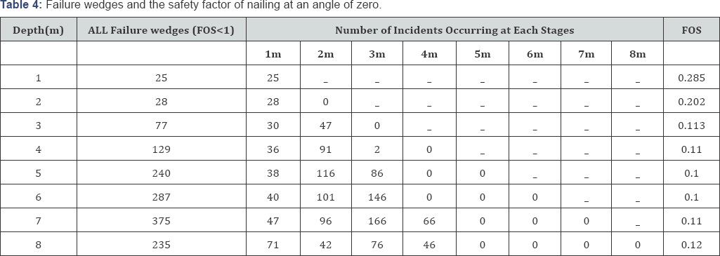
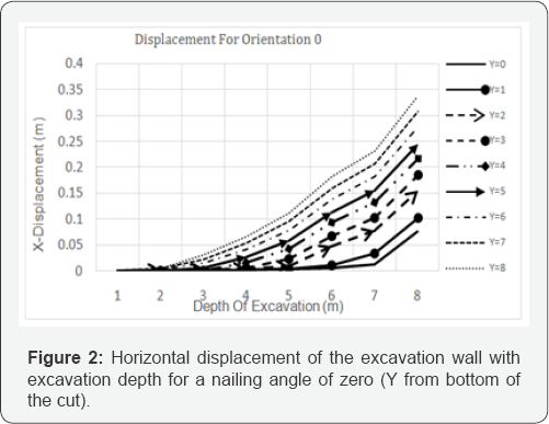
Given the horizontal displacements of the wall shown in Figure 2, it can be stated that displacements mostly occur after excavation of second 4 meters in upper half of the facing during nailing at an angle of zero degrees, and the soil behavior and formation of the failure wedge is such a way that horizontal nailing is suitable to prevent possible slips in second half of the facing; while the upper half of the facing has the largest displacements of about 35cm, indicating the probability of abundant settlements and ruptures in surrounding structures (Table 4). If a nailing angle of 5 degrees with the horizontal is applied, failure wedges and horizontal displacements can be expressed in accordance with Figure 3 and Table 5.

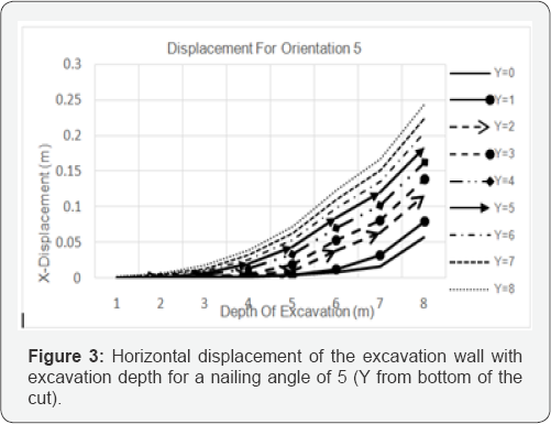
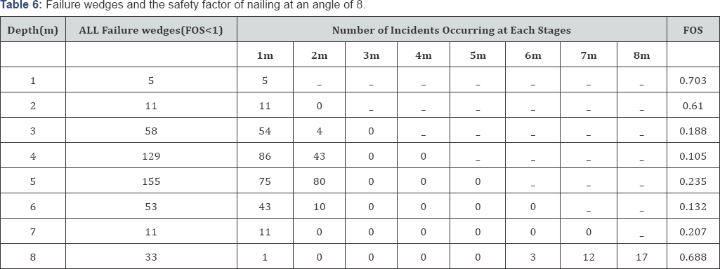
According to the results obtained through analysis the nailing performed at a 5-degree angle with the horizontal, it can be stated that although safety factor of wedges is initially improved in the half of the work in comparison with horizontal nailing (Table 5) and horizontal displacements are also decreased (Figure 3), the displacement can cause larger masses to slip in second half of the excavation (second 4 meters). Hence, a lower safety factor is observed compared to what would happen in zero-degree nailing but the horizontal displacement is about 30% less than nailing at a zero degree angle, while displacement values are still very high (about 25cm). The noticeable point in nailing at an angle of 8 degrees is disappearance of all failure wedges at the middle of excavation cut, although its weakness in controlling the wedges initially prone to slip is obvious, as seen in Table 6.
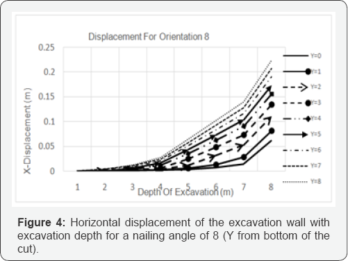
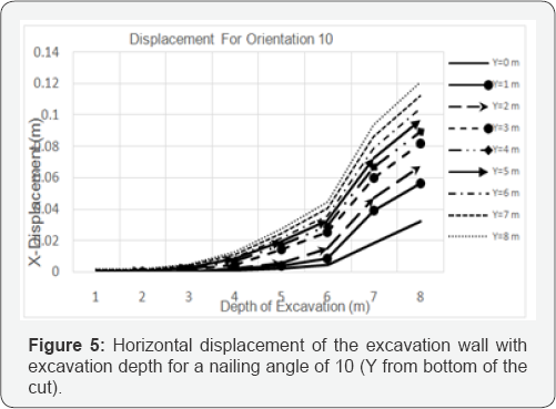

According to the results illustrated in Figure 4, maximum horizontal displacement of the excavation wall in the case of nailing at an angle of 8 degrees is less than 10% of displacements in nailing at a 5 degree angle. But generally, the nailing system at an angle of 8 degrees has a more optimal behavior in terms of the number of potential failure wedges than nailing at an angle of 5 degrees. According to the results demonstrated in Figure 5and Table 7, it can be observed that maximum horizontal deformation of the facing in the nailing system at a 10 degree angle is reduced to one-third of the zero-degree mode and to the half of the 5-degree mode; moreover, in both modes mentioned above (an angle of zero and 5 degrees), maximum horizontal deformation of the slope and maximum deformation of the excavation wall occurs in the last 1 meter increment of the excavation; in other words, the last step being dug is the most dangerous part of excavation.
But in case of nailing at an angle of 10 degrees with the horizontal, the most critical part of excavation is between the last 6 and 7 meters (Figure 5). However, given the safety factors and potential failure wedges and considering Table 7 and neglecting small failure wedges at the beginning of the excavation, it can be seen that there will be no potential sliding wedges up to a depth of 6 meters with a good safety factor. However, sliding wedges must be expected in the last two steps.
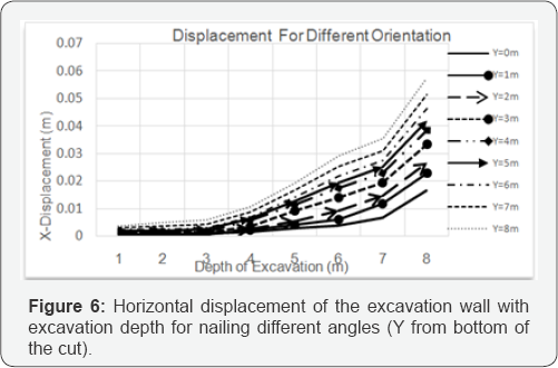
If nailing system is implemented at different angles, significant changes would be made to the results. As seen in Figure 6, the minimum horizontal displacement associated with nailing occurs when a critical wedge is applied among potential failure wedges instead of inserting all nails at the same nailing angle, assuming that the nail always makes a vertical angle with the surface of the wedge, not with the horizontal. It must be noted that intersection point of the nail and the surface of this wedge is different from previous states (in terms of constant angle of the nail with the horizontal), but the nail is rotated on the intersection point to become perpendicular to the failure surface.
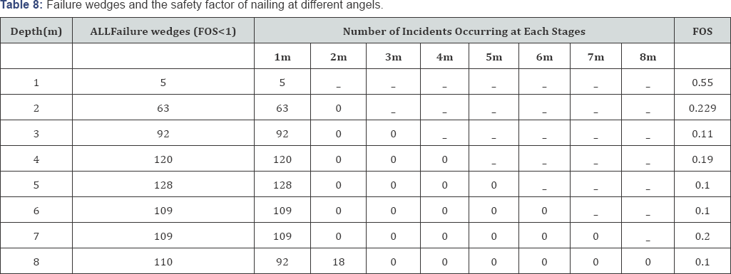
The table of wedges (Table 8) also confirms these small horizontal deformations; the reason is that except for a series of small slopes occurred in one meter above and the boundary of whole excavation path, the rest of soil-to-ground interaction path results in an improved nailing performance for nailing at different angles in excavation depth. Because of limitations upon finding proper location of nails in this model (at different angles), one of the nails is necessarily omitted; so that seven nails are employed in this case (at different angles), rather than eight nails in previous states (at a constant angle), at nailing angle of 26, 28, 30, 32, 35, 37 and 40 degrees, respectively.
Conclusion
In case of vertical excavation of weak clay soil, a series of unstable soil wedges are always encountered during excavation. If a wedge is considered critical among these wedges, performance of the nailing system can be significantly improved and optimized by modifying the nailing angle in each phase of nailing, assuming that the nail must always be perpendicular to the surface of critical wedge. According to this hypothesis, maximum horizontal displacement of the facing in case of using a 6 meter nail at a different angle is considerably lower than other models (at angles of 0, 5, 8, and 10), so that maximumdisplacements of the excavation wall in nailing systems with various angles, different from 0, 5, 8 and 10, are 35.25, 22, 12, and 5.5 centimeters, respectively.
References
- United States, Federal Highway Administration, French National Research Project CLOUTERRE (1991) Soil nailing recommendations-1991. Federal Highway Administration, FHWA- SA-93-026, Washington, USA, p. 302.
- Su LJ, Yin JH, Zhou WH (2010) Influences of overburden pressure and soil dilation on soil nail pull-out resistance. Computers and geotechnics 37(4): 555-564.
- Yongmin K, Sungjune L, Sangseom J, Jaehong K (2013) The effect of pressure-grouted soil nails on the stability of weathered soil slopes. Computers and geotechnics 49(2013): 253-263.
- Zhangn G, Cao J, Liping W (2014) Failure behavior and mechanism of slopes reinforced using soil nail wall under various loading conditions. Soil and foundation 54(6): 1175-1187.
- Chia-CF, Jiun HL (2008) Numerical study on the optimum layout of soil-nailed slopes. EJGE 22(2017): 3966-3984.
- GEO-SLOPE International Ltd (2017) GeoStudio Universal v11.11.0.0 build 106800. Calgary, Canada.
- ACI Commttee 506 (1990) Guide to Shotcrete.


